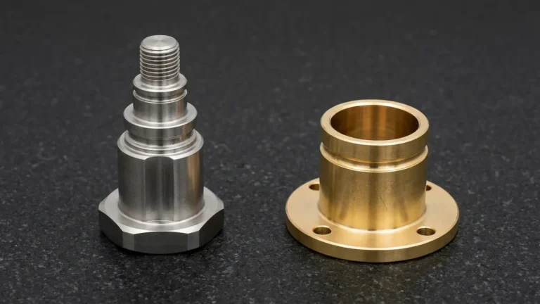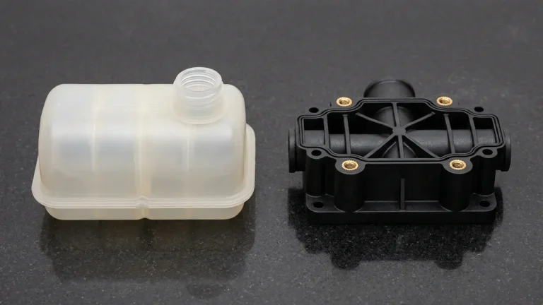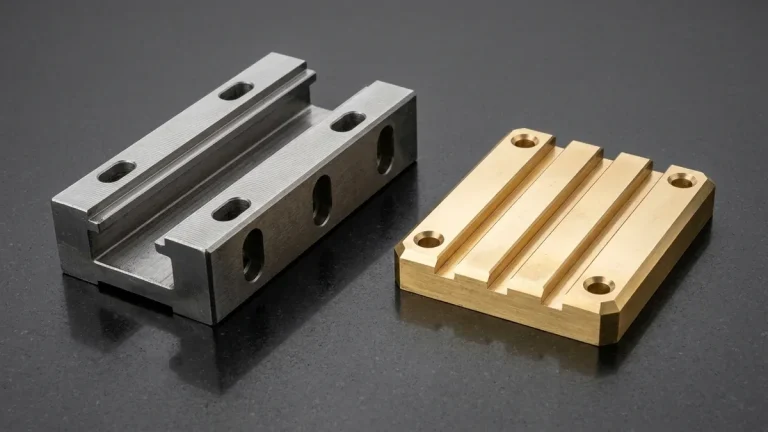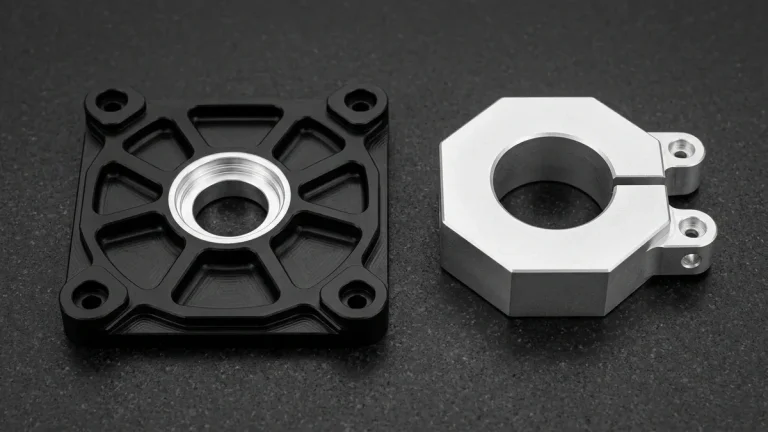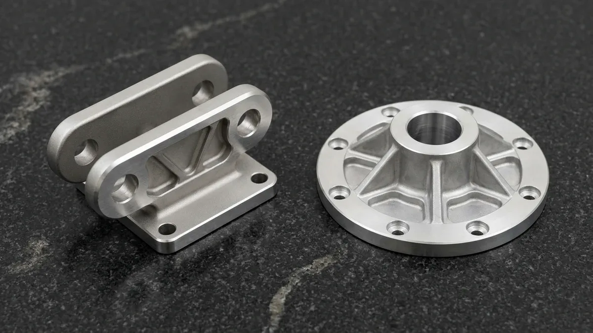
Evaluating investment casting vs die casting requires balancing metallurgical melting-point physics against tooling amortization and downstream machining allowances. While lost-wax investment casting pours molten ferrous and non-ferrous alloys at temperatures up to 1,650°C (3,002°F) into expendable ceramic shells, high-pressure die casting (HPDC) injects molten light metals at 30–120 MPa (4,350–17,400 psi) into permanent hardened steel dies.
Neither foundry process natively achieves precision bearing fits or hydraulic sealing flatness straight from the mold cavity. As-cast linear tolerances governed by ISO 8062-3 span ±0.21 mm to ±0.41 mm (±0.008″ to ±0.016″) for silica-sol investment castings and ±0.15 mm to ±0.29 mm (±0.006″ to ±0.011″) for high-pressure die castings at a 16–25 mm (0.63″–1.0″) nominal dimension.
In our Shenzhen manufacturing facility, we integrate precision foundry casting with high-speed 3-axis and 4-axis CNC post-machining under one workflow. By engineering 0.3 mm to 1.5 mm (0.012″ to 0.060″) machining allowances onto functional datums, our in-house team holds ±0.010 mm to ±0.020 mm (±0.0004″ to ±0.0008″) bore tolerances across batches from 50 to 100,000+ units.
Executive Summary & Engineering Takeaways (BLUF)
- Metallurgical Melting-Point Boundary: Investment casting uses refractory zircon-silica shells firing at 950°C–1,100°C (1,742°F–2,012°F) to cast high-temperature ferrous stainless steels (304, 316L, 17-4PH), alloy steels (4140 / 42CrMo4), and A356-T6 aluminum. High-pressure die casting utilizes water-cooled H13 steel dies (46–50 HRC) restricted strictly to non-ferrous aluminum (ADC12 / A383, A380), zinc (Zamak 3/5), and magnesium (AZ91D) below 680°C (1,256°F).
- ISO 8062-3 Tolerance & Roughness Divide: Silica-sol investment casting holds ISO 8062-3 DCTG 5–7 (CT5–CT7, ±0.21–0.41 mm / ±0.008″–0.016″ at 25 mm) with an isotropic grain structure and Ra 1.6–3.2 µm (63–125 µin) finish. High-pressure die casting holds DCTG 4–6 (CT4–CT6, ±0.15–0.29 mm / ±0.006″–0.011″ at 25 mm) with Ra 0.8–1.6 µm (32–63 µin) cast skin.
- Wall Thickness & Draft Geometry: High-pressure cavity injection at 30–60 m/s (98–197 ft/s) fills thin 1.0–2.0 mm (0.039″–0.079″) aluminum walls and 0.6–1.2 mm (0.024″–0.047″) zinc walls, but mandates 1.0°–3.0° ejection draft. Investment casting requires 1.5–2.5 mm (0.060″–0.098″) walls under gravity feed while allowing 0°–0.5° draft and complex internal undercuts via soluble wax cores.
- CNC Post-Machining Chill-Skin Rule: Both processes require 3-axis/4-axis VMC post-machining for ±0.010–0.020 mm (±0.0004″–0.0008″) datums and H7 bearing bores. However, HPDC machining depth must stay within 0.3–0.6 mm (0.012″–0.024″) per side so cutters do not breach the dense 0.5–0.8 mm (0.020″–0.031″) outer chill skin into subsurface gas porosity.
- Tooling Amortization Crossover: Machined 6061-T6 aluminum wax dies (1.0x tooling index) make investment casting optimal for 50 to 5,000 units. Hardened H13 multi-slide steel dies (3.5x–6.5x tooling index) require 3,000 to 5,000+ non-ferrous units to amortize tooling via 20–45 second automated shot cycles.
Article Engineering Navigation
1. Thermodynamic & Tooling Mechanics: Lost-Wax Ceramic Shells vs High-Pressure Steel Dies
The fundamental engineering divergence in investment casting vs die casting stems from mold permanence and cavity filling pressure. Silica-sol investment casting is an expendable-mold, sacrificial-pattern process governed by low-turbulence gravity or vacuum-assisted pouring. Conversely, high-pressure die casting (HPDC) is a permanent-mold process driven by high-velocity hydraulic plunger injection into water-cooled tool steel cavities.
In silica-sol investment casting, production begins by CNC milling a precision wax-injection die from wrought 6061-T6 or 7075-T6 aluminum alloy. Because molten pattern wax injectors operate at low pressures of 1.5–4.0 MPa (218–580 psi) and low temperatures of 65°C–75°C (149°F–167°F), the aluminum wax die experiences negligible thermal or mechanical wear over tens of thousands of cycles.
Foundry engineers expand the aluminum wax cavity dimensions by 1.5% to 2.2% to compensate for dual-stage volumetric contraction: pattern wax shrinkage (0.6%–0.9%) plus alloy solidification shrinkage (1.0%–1.6% for stainless steel). Ejected wax patterns are hand-welded or robotically gated onto a central wax sprue runner tree capable of casting 8 to 60 components per pour.
The wax cluster undergoes robotic dipping into a colloidal silica slurry blended with 325-mesh zircon flour (ZrSiO4), followed by refractory aluminosilicate stucco raining. After building 6 to 9 ceramic coats (total shell thickness 6.0–10.0 mm / 0.236″–0.394″), the assembly cures in humidity-controlled rooms for 48 to 96 hours.
Next, high-pressure steam autoclaves operating at 150°C–180°C (302°F–356°F) and 0.6–0.8 MPa (87–116 psi) melt out 98% of the sacrificial wax without cracking the green ceramic shell. The hollow ceramic mold is then sintered in firing furnaces at 950°C–1,100°C (1,742°F–2,012°F) to burn off residual hydrocarbons and preheat the shell prior to pouring molten metal.
High-pressure die casting eliminates sacrificial patterns and multi-day shell building by injecting molten metal directly into a two-piece hardened H13 or SKD61 hot-work tool steel die heat-treated to 46–50 HRC. For aluminum and magnesium alloys, cold-chamber HPDC machines ladle a metered shot of liquid metal into a horizontal hardened steel shot sleeve.
A hydraulic plunger advances in three programmed stages: a slow-shot phase at 0.2–0.5 m/s (0.66–1.64 ft/s) to push air ahead of the molten wave, a fast-shot phase accelerating the melt through thin gates at 30–60 m/s (98–197 ft/s) to fill the cavity in 15–60 milliseconds, and a final intensification phase applying 30–120 MPa (4,350–17,400 psi) during solidification.
2. The Metallurgical Melting-Point Divide: Ferrous Superalloys vs Non-Ferrous Light Metals
Material selection frequently settles the investment casting vs die casting decision before geometry or volume is even considered. Because investment casting pours molten metal into an inert refractory zircon-silica ceramic shell rated above 1,750°C (3,182°F), it processes high-melting-point ferrous steels, nickel superalloys, cobalt-chrome, and non-ferrous aluminum or bronze alloys with equal reliability.
High-pressure die casting cannot process stainless steels, carbon steels, or titanium alloys. Ferrous melts require 1,450°C–1,650°C (2,642°F–3,002°F), far exceeding the 550°C–600°C (1,022°F–1,112°F) tempering limit of H13 steel dies. Injecting liquid steel at 40 m/s (131 ft/s) rapidly softens the cavity, triggers thermal-shock cracking, and welds the casting to the die walls.
Consequently, high-pressure die casting is restricted strictly to non-ferrous alloys with liquidus temperatures below 680°C (1,256°F). In high-pressure die-casting foundries, aluminum alloys ADC12 (JIS / ASTM A383 equivalent) and A380 account for over 80% of housing volume, pouring at 640°C–680°C (1,184°F–1,256°F) in 160- to 2,500-ton cold-chamber machines.
Die-cast aluminum alloys such as ADC12 and A380 contain 7.5% to 12.0% silicon to lower viscosity and maximize thin-wall fluidity, alongside a deliberate 0.8% to 1.1% iron content. In wrought aluminum, iron is an impurity; in HPDC, roughly 1.0% dissolved iron is mandatory to prevent molten aluminum from chemically dissolving and soldering onto the H13 steel die surface.
For miniature thin-wall gears, connector shields, and lock mechanisms, hot-chamber die casting processes zinc alloys Zamak 3, Zamak 5, and ZA-8 at 410°C–440°C (770°F–824°F). Because molten zinc does not attack submerged steel gooseneck plungers at 420°C (788°F), zinc HPDC achieves rapid 6–15 second cycles and die lifetimes exceeding 500,000 to 1,000,000 shots.
When applications demand corrosion resistance, high tensile yield strength above 1,000 MPa (145 ksi), or service temperatures above 250°C (482°F), silica-sol investment casting is mandatory. Our foundry regularly pours austenitic 304 (CF8) and 316L (CF3M) stainless steels, carbon and chromoly alloy steels (1045, 4140 / 42CrMo4, 8620), and precipitation-hardening 17-4PH (CB7Cu-1) stainless steel.
Following investment casting, 17-4PH stainless steel undergoes H900 precipitation aging at 482°C (900°F) for 60 minutes to reach 40–44 HRC (1,310 MPa / 190 ksi UTS). Likewise, laminar-poured A356 aluminum accepts full 535°C (995°F) T6 solution heat treatment—unlike conventional air-vented HPDC castings, where 535°C heating expands trapped internal gas pores into severe surface blisters.
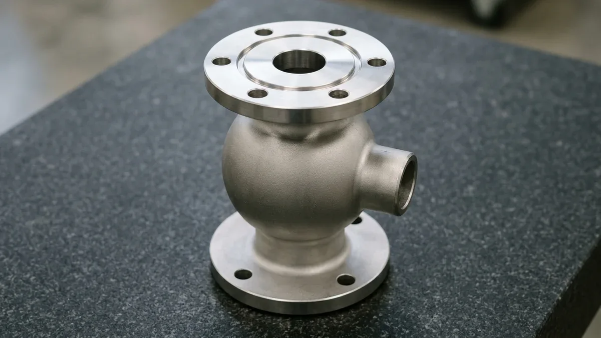
As shown in the 316L stainless steel valve body below, silica-sol ceramic shells form bulbous internal chambers with an isotropic Ra 3.2 µm (125 µin) cast skin. Subsequent 3-axis CNC face milling establishes a mirror-bright Ra 0.8 µm (32 µin) raised-face top sealing ring, a concentric central bore, and six bolt holes.
3. Solidification Thermodynamics & Clamping Force Derivations (Chvorinov’s Rule & HPDC Tonnage)
Rigorous foundry engineering relies on quantitative solidification modeling to eliminate internal shrinkage cavities in investment castings and prevent parting-line flash in high-pressure die castings. During our upfront Design for Manufacturing (DFM) engineering review, we evaluate two governing equations before cutting aluminum wax dies or H13 steel molds.
3.1 Chvorinov’s Solidification Rule & Casting Modulus for Investment Casting
In gravity-poured investment casting, molten metal solidifies directionally from the thinner outer walls toward the heaviest thermal nodes and feed gates. Local solidification time is governed by Chvorinov’s Rule, which relates solidification duration to the square of the local volume-to-cooling-surface-area ratio, defined as the casting modulus (M):
Equation 1: Chvorinov’s Solidification Time & Casting Modulus Criterion
ts = B × (V ÷ A)n = B × M2 | Riser Feeding Rule: Mriser ≥ 1.20 × Msection
- ts = Total local solidification time (seconds, s)
- V = Volume of the local casting section or boss (mm3 or in3)
- A = Heat-dissipating surface area in contact with the ceramic shell (mm2 or in2)
- M = V ÷ A = Geometric casting modulus (mm or in), governing thermal mass cooling sequence
- B = Mold constant (s/mm2), dependent on alloy latent heat, superheat, and ceramic shell thermal conductivity
- n = Empirical thermal diffusivity exponent (n = 2.0 for refractory ceramic shells)
Worked Solidification Example: Consider a 316L stainless steel valve body with a 4.0 mm (0.157″) uniform chamber wall intersecting an 18.0 mm (0.709″) thick un-cored flange boss. A flat plate of thickness t cools from both sides, yielding a baseline wall modulus of Mwall = t ÷ 2 = 4.0 ÷ 2 = 2.0 mm (0.079″).
Conversely, the cylindrical boss of diameter D = 36.0 mm (1.417″) and height H = 18.0 mm (0.709″) has volume V = 18,321.8 mm3 (1.118 in3) and shell-contact cooling area A = 3,053.6 mm2 (4.733 in2, excluding the chamber junction), giving Mboss = 18,321.8 ÷ 3,053.6 = 6.0 mm (0.236″).
Because solidification time scales with M2, the heavy boss takes (6.0 ÷ 2.0)2 = 9.0 times longer to freeze than the adjacent 4.0 mm (0.157″) wall. This thermal lag creates an isolated internal shrinkage cavity unless gated directly to a feeder sprue with Mriser ≥ 7.2 mm (0.283″) or cored out to reduce wall thickness.
3.2 High-Pressure Die Casting Clamping Force & Machine Tonnage Calculation
In high-pressure die casting, the hydraulic toggle clamping mechanism must resist the hydrostatic opening force generated when cavity intensification pressure (Pspec = 30–120 MPa / 4,350–17,400 psi) acts across the total projected area on the parting plane. Required machine clamping tonnage is calculated as:
Equation 2: HPDC Hydraulic Die Clamping Tonnage Formula
Fclamp (metric tons) = (Aproj,total × Pspec × ksafety) ÷ 98.07
- Aproj,total = Total projected area on the die parting plane, including part cavity, runner system, biscuit, and overflow wells (cm2; typically 1.35 × to 1.55 × part projected area; if measured in mm2, divide by 9,806.65)
- Pspec = Specific cavity intensification pressure (MPa; 40–60 MPa for cosmetic housings, 70–100 MPa for dense structural/pressure-tight aluminum castings)
- ksafety = Dynamic momentum surge and flash-prevention safety factor (1.15 to 1.25; increases by 15% when angled mechanical side-core slides are present)
- 98.07 = Gravitational conversion constant (98.0665) from 100 N (cm2 × MPa) to metric tons-force (tf)
Worked Tonnage Example: For an ADC12 rotary drive hub of diameter D = 190 mm (7.48″), net part projected area is Apart = π × 9.52 = 283.53 cm2 (43.95 in2). Adding 48% for the biscuit, runner, and overflow wells yields Aproj,total = 420.0 cm2 (65.10 in2).
To prevent internal porosity around the bearing hub, we specify Pspec = 80 MPa (11,603 psi) and a safety factor of ksafety = 1.20. Substituting into Equation 2 yields Fclamp = (420.0 × 80 × 1.20) ÷ 98.07 = 411.13 metric tons (453.2 US short tons), scheduling production on a 500-ton cold-chamber cell.
4. Dimensional Tolerances (ISO 8062-3), Wall Thickness & Surface Roughness Comparison
Both casting technologies are classified as near-net-shape processes under ISO 8062-3 (GPS — Dimensional and geometrical tolerances for molded parts — Part 3: Castings), yet their precision envelopes differ due to thermal expansion physics. Permanent H13 steel dies maintain rigid cavity geometry under water/oil thermal regulation at 180°C–240°C (356°F–464°F), delivering superior shot-to-shot linear repeatability.
High-pressure die casting routinely achieves ISO 8062-3 DCTG 4 to DCTG 6 (CT4–CT6) tolerances. Within a single die half, aluminum and zinc HPDC hold ±0.15 mm to ±0.29 mm (±0.006″ to ±0.011″) at 16–25 mm (0.63″–1.0″), and ±0.22 mm to ±0.44 mm (±0.009″ to ±0.017″) across 100–160 mm (3.94″–6.30″) spans, plus ±0.10–0.20 mm (±0.004″–0.008″) across parting lines.
Silica-sol investment casting experiences cumulative thermal shifts across wax injection, dewaxing, shell firing at 1,050°C (1,922°F), and alloy solidification. Consequently, investment castings conform to ISO 8062-3 DCTG 5–7 (CT5–CT7), holding ±0.21–0.41 mm (±0.008″–0.016″) at 16–25 mm (0.63″–1.0″) and ±0.31–0.60 mm (±0.012″–0.024″) across 100–160 mm (3.94″–6.30″) spans.
However, investment casting holds a major geometric advantage across parting planes and internal undercuts. Because the ceramic shell is formed monolithically around a one-piece or soluble-core wax pattern, investment castings have zero steel-die parting shift, zero slide witness steps, and require only 0°–0.5° draft versus 1.0°–3.0° mandatory ejection draft in HPDC.
| Engineering Parameter | Silica-Sol Investment Casting (Lost-Wax) | High-Pressure Die Casting (HPDC) | Recommended Application / When to Choose |
|---|---|---|---|
| Mold & Tooling Architecture | 6061-T6 aluminum wax die + expendable 6–9 coat zircon/silica ceramic shell (single pour) | Permanent hardened H13 / SKD61 hot-work steel die (46–50 HRC; 80,000–150,000+ Al shots) | Choose investment casting for low upfront tooling capital and rapid design iterations; choose HPDC for high-volume repeatability. |
| Compatible Alloy Families | Ferrous & Non-Ferrous: 304, 316L, 17-4PH SS (H900), 4140/42CrMo4 steel, A356-T6 Al, Bronze | Strictly Non-Ferrous (<680°C / 1,256°F): Aluminum (ADC12 / A383, A380), Zinc (Zamak 3/5), Magnesium (AZ91D); no 535°C (995°F) T6 on air-vented HPDC | Choose investment casting for stainless steel, alloy steel, or T6 heat-treated structural alloys; choose HPDC for lightweight Al/Zn/Mg housings. |
| Linear Casting Tolerance (ISO 8062-3) | DCTG 5 to DCTG 7 (CT5–CT7): ±0.21 to ±0.41 mm (±0.008″ to ±0.016″) at 16–25 mm (0.63″–1.0″) | DCTG 4 to DCTG 6 (CT4–CT6): ±0.15 to ±0.29 mm (±0.006″ to ±0.011″) at 16–25 mm (+0.15 mm / +0.006″ across parting line) | Choose HPDC when tight as-cast outer boss spacing is needed; plan CNC post-machining on both for ±0.010–0.020 mm (±0.0004″–0.0008″) fits. |
| As-Cast Surface Roughness (ISO 4287) | Ra 1.6 to 3.2 µm (63 to 125 µin) uniform isotropic matte ceramic texture | Ra 0.8 to 1.6 µm (32 to 63 µin) smooth dense chill skin replicated from polished H13 steel | Choose HPDC for smooth powder-coated consumer/automotive housings; choose investment casting for bead-blasted or electropolished steel parts. |
| Minimum Wall Thickness | 1.5 to 2.5 mm (0.060″ to 0.098″) standard; 1.0 mm (0.039″) over localized spans <25 mm (1.0″) | Aluminum: 1.0 to 2.0 mm (0.039″ to 0.079″); Zinc: 0.6 to 1.2 mm (0.024″ to 0.047″) | Choose HPDC for ultra-thin heat sink fins, EMI shielding ribs, and lightweight thin-walled electronics frames. |
| Draft Angles & Internal Undercuts | 0° to 0.5° external draft; complex internal undercuts and curved passages via soluble wax or ceramic cores | 1.0° to 2.5° outer wall draft (2.0°–3.5° on core pins); internal undercuts forbidden unless machined or formed by straight side slides | Choose investment casting for closed-shroud impellers, curved fluid valve galleries, and re-entrant internal cavities. |
| Recommended CNC Machining Stock | 0.8 to 1.5 mm (0.031″ to 0.060″) per side on functional datums and bores | Strictly 0.3 to 0.6 mm (0.012″ to 0.024″) per side (never exceed 0.8 mm / 0.031″ to protect chill skin) | Use our integrated casting + 3/4-axis CNC milling workflow to hold ±0.010 mm (±0.0004″) critical features without porosity exposure. |
| Relative Tooling Investment & Volume Sweet Spot | Low Tooling Investment (1.0x baseline index); optimal for 50 to 5,000 units per year | High Tooling Investment (3.5x to 6.5x relative index); optimal for 3,000 to 500,000+ units | Bridge 1–50 units via direct CNC billet machining, scale 50–5,000 via investment casting, and transition >5,000 non-ferrous units to HPDC. |
5. Turnkey Foundry-to-CNC Workflow: Casting Stock Allowances & CNC Post-Machining
A frequent sourcing mistake in global hardware procurement is ordering raw castings from a standalone foundry and shipping them to a separate machine shop. When dimensional stacked errors or subsurface porosity appear during milling, the foundry blames the machinist’s datum setup while the machine shop blames core shift in the raw casting.
At our Shenzhen facility, we eliminate this accountability gap by managing wax/die tooling, foundry pouring, and precision CNC machining services under one quality plan. We engineer two distinct CAD models per project: the As-Cast Foundry Model (with shrinkage, draft, and stock) and the Finish-Machined Print Model (holding ISO 2768-mK and ±0.010–0.020 mm / ±0.0004″–0.0008″ critical datums).
Crucially, CNC machining stock strategies differ fundamentally between investment castings and die castings. On silica-sol investment castings in 304, 316L, or 17-4PH stainless steel, we add 0.8 mm to 1.5 mm (0.031″ to 0.060″) of stock per side so our 3-axis and 4-axis CNC milling centers cut completely beneath the decarburized surface layer.
Conversely, high-pressure die castings require strict adherence to the Chill-Skin Preservation Rule. When molten ADC12 or A380 aluminum hits the water-cooled H13 steel cavity at 50 m/s (164 ft/s), rapid solidification at 100°C/s–1,000°C/s forms a dense outer skin 0.5–0.8 mm (0.020″–0.031″) thick, while compressed gas pores remain trapped deeper inside.
Therefore, we strictly cap CNC post-machining stock on high-pressure die castings at 0.3 mm to 0.6 mm (0.012″ to 0.024″) per side. Removing 1.2 mm (0.047″) from a die-cast flange or drilling into an un-cored boss breaches the dense chill skin and exposes internal micro-porosity—causing 3.5–6.0 bar (51–87 psi) pressure leaks and plating blisters.
- Establish As-Cast 3-2-1 Datum Target Pads in Tooling Design: Before cutting the wax mold or H13 steel die, our DFM engineers place three coplanar cast locator pads (Datum A), two axial alignment bosses (Datum B), and one lateral stop boss (Datum C) on non-parting, zero-flash surfaces of a single mold half to guarantee repeatable first-operation (OP10) CNC clamping.
- Fixture Castings in Custom 3D Contoured Soft Jaws or Hydraulic Workholding: Because cast exterior walls carry 1°–2.5° draft angles or organic curvatures, clamping raw castings in flat steel vise jaws crushes thin walls. Our Brother and Haas 3-axis and 4-axis VMCs use CNC-milled 6061-T6 contoured soft jaws or pneumatic/hydraulic multi-point toggle fixtures with ≥70% footprint support to clamp without distortion.
- Machine Critical Sealing Faces, H7 Bearing Bores, and Tapped Threads: Using high-pressure through-spindle coolant and PCD (polycrystalline diamond) or PVD-coated carbide tooling, we skim-mill sealing flanges to Ra 0.8 µm (32 µin) with flatness within 0.020 mm (0.0008″), fine-bore H7 bearing seats (e.g., Ø40 H7: +0/+0.025 mm / +0/+0.001″), and machine critical datums to ±0.010–0.020 mm (±0.0004″–0.0008″).
- Verify Geometric Tolerances and Pressure Tightness in Our 20°C ± 1°C Metrology Room: Finished castings undergo XRF alloy verification, stylus profilometer checks (ISO 4287), 3-point internal bore micrometer and thread Go/No-Go plug gauging, 3.5–6.0 bar (51–87 psi) pressure-decay leak testing, Dimensional First Article Inspection (FAI) with Ballooned Drawing reports, and Zeiss bridge CMM verification (available upon request).
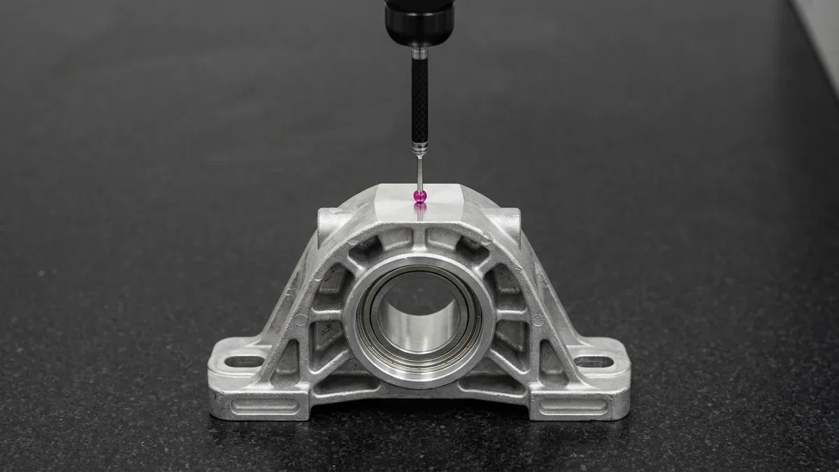
The inspection photograph below demonstrates this turnkey workflow on a high-pressure die-cast A380 aluminum pillow-block bearing housing. While the exterior cored weight-reduction pockets retain their matte die-cast draft ribs, the central bearing bore (with retaining ring groove) and flat top datum boss are CNC post-machined to ±0.010 mm (±0.0004″) for bridge CMM ruby probe verification.
6. Casting Defect Troubleshooting, DFM Rules & Surface Finishing Compatibility
Designing a component for casting requires fundamentally different geometric rules than designing for solid billet milling. In solid CNC machining, thick cross-sections and sharp transitions simply mean less material removal; in both investment casting and die casting, abrupt wall-thickness transitions create localized thermal hot spots, shrinkage voids, and residual tensile stresses during cooling.
To prevent hot tearing and shrinkage porosity in investment castings, wall transitions must follow a gradual 3:1 taper slope, and internal L-, T-, and X-junctions require fillets of R = 1.5–3.0 mm (0.060″–0.118″). Additionally, deep blind slots must maintain sufficient width-to-depth clearance so refractory zircon slurry and stucco grains penetrate without bridging during shell dipping.
In high-pressure die casting, the primary DFM rule is Uniform Wall Thickness & Aggressive Coring (Rib-to-Wall Ratio 0.5t–0.7t). Rather than designing a 10.0 mm (0.394″) solid flange on an automotive powertrain housing, engineers hollow out the section into a 2.0–2.5 mm (0.079″–0.098″) shell reinforced by 1.2–1.5 mm (0.047″–0.060″) stiffening ribs and cored bosses.
Surface finishing behavior also diverges sharply between cast and wrought alloys. Hardware engineers frequently specify decorative clear or dyed sulfuric acid anodizing (MIL-A-8625 Type II) on die-cast ADC12 or A380 aluminum, only to discover that the 7.5%–12.0% elemental silicon precipitates do not anodize—turning the part a blotchy, non-uniform dark slate grey.
Instead, for die-cast aluminum parts requiring corrosion protection across our custom surface finishing line, we apply trivalent chromate conversion coating (SurTec 650 / MIL-DTL-5541 Type II, dried strictly ≤60–65°C / 140–149°F) before e-coating (15–35 µm / 0.6–1.4 mil) or powder coating (60–120 µm / 2.4–4.7 mil) rated for 240+ hours of ASTM B117 salt spray.
| Defect / DFM Failure Mode | Primary Root Cause in Foundry / CNC | Quantitative DFM & Process Countermeasure | Recommended Application / When to Choose |
|---|---|---|---|
| Exposed Subsurface Gas Porosity After CNC Milling (HPDC) | Machining depth exceeds 0.8 mm (0.031″), cutting through the dense chill skin into trapped turbulent gas pores | Limit HPDC machining stock to 0.3–0.6 mm (0.012″–0.024″); pre-core all tapped bosses in the H13 die; add vacuum venting for pressure-tight parts | Mandatory on pneumatic/hydraulic manifolds, IP68 enclosures, and automotive liquid-cooled housings. |
| Internal Shrinkage Cavities at Heavy Bosses (Both Processes) | Isolated thick boss has high Chvorinov modulus (M = V ÷ A) and freezes after surrounding thin walls cut off liquid feeding | Core out heavy bosses (wall ≤2.5 mm / 0.098″ in HPDC; ≤6.0 mm / 0.236″ in investment casting) or place direct feeder gates with Mriser ≥ 1.2 × Mboss | Apply to all rotary drive hubs, valve flanges, and thick structural mounting brackets. |
| Ceramic Shell Cracking or Bridging in Deep Slots (Investment Casting) | Blind slots or holes narrower than 2.5 mm (0.098″) trap air during slurry dipping and prevent zircon stucco drying | Keep as-cast blind hole depth ≤1.5 × diameter (through-holes ≤4 × diameter), or use preformed leachable ceramic cores for narrow internal passages | Essential for closed-shroud stainless steel impellers and multi-port valve bodies. |
| Die Soldering & Ejection Drag Marks (HPDC) | Insufficient draft angle (<0.5°) on deep internal core pins or low iron content (<0.7% Fe) in aluminum melt | Specify 1.5°–2.5° draft on outer walls and 2.0°–3.5° on internal core pins; PVD TiAlN/CrN coat H13 core pins and maintain 0.8%–1.1% Fe in ADC12/A380 | Critical for deep-finned telecom heat sinks and tall cylindrical bearing bosses in HPDC. |
| Blotchy Dark Grey Smut After Anodizing Die-Cast Aluminum | High silicon content (7.5%–12.0% Si in ADC12/A380) leaves unanodized eutectic silicon particles that darken the oxide during sulfuric anodizing | Replace MIL-A-8625 anodizing on ADC12/A380 with SurTec 650 chromate + powder coating/e-coating, or machine cosmetic anodized parts from 6061-T6 billet | Choose powder-coated HPDC for industrial enclosures; choose CNC-milled 6061-T6 for cosmetic clear/color anodized finishes. |
7. Tooling Amortization, Production Lead Times & When NOT to Choose Casting
From a program management perspective, comparing investment casting vs die casting comes down to tooling amortization volume and ex-factory schedule buffers. Because investment casting wax dies are CNC-milled from 6061-T6 aluminum without hardened steel EDM or hydraulic slide cylinders, upfront tooling investment sits at a normalized 1.0x baseline index.
In contrast, a production HPDC mold requires vacuum-hardened H13 or SKD61 steel cavities (46–50 HRC), nitrided ejector pins, water cooling lines, and hydraulic core pulls—representing a 3.5x to 6.5x relative tooling index. Once mounted in an automated cold-chamber cell, 20–45 second shot cycles reduce unit piece cost by 60%–80% versus ceramic-shell casting.
Consequently, for non-ferrous aluminum or zinc components where either process is metallurgically viable, 50 to 3,000 units favors investment casting due to rapid tooling amortization. Above 3,000 to 5,000+ units, high-pressure die casting rapidly overtakes investment casting in total landed program economy.
For turnkey production scheduling, our team returns custom RFQ and DFM reviews within 24 hours (24–48 hours for multi-slide dies), strictly separating Ex-Factory Production & Inspection Turnaround from 3–5 business days of air freight (DHL/FedEx/UPS). Standard ex-factory turnaround for aluminum wax tooling and T1 CNC-machined investment castings is 18 to 35 business days.
For high-pressure die casting, fabricating the hardened H13 steel die and delivering T1 cast-and-machined samples likewise requires 18 to 35 business days ex-factory. Subsequent low-to-mid volume investment casting or HPDC production runs coupled with 3-axis/4-axis VMC finish machining and surface finishing complete in 7 to 30 business days ex-factory depending on batch quantity and inspection scope.
7.1 When NOT to Choose Investment Casting or Die Casting (Process Limitations & Trade-Offs)
Even though casting excels at near-net-shape production, neither foundry route is a universal solution for every mechanical assembly. During upfront DFM reviews, there are four specific engineering scenarios where our team advises hardware leads to bypass both investment casting and die casting in favor of alternative manufacturing processes:
- 1. Low-Volume Prototypes & Bridge Runs (1 to 50 Units): Waiting 18–35 business days and amortizing wax or steel tooling across 10 prototype parts is uneconomical. For 1 to 50 pieces, direct 3-axis and 4-axis CNC milling from wrought 6061-T651, 7075-T651, or 316L bar/plate stock delivers finished parts in 4 to 8 business days ex-factory (7 to 12 business days with surface finishing) with zero tooling investment.
- 2. High-Fatigue Structural & Safety-Critical Aerospace Fittings: Even well-fed castings exhibit dendritic grain structures, lower elongation (2%–4% in ADC12 HPDC vs. 11%–15% in wrought 6061-T6), and microscopic porosity that reduces fatigue endurance limits. For primary flight brackets or high-shock suspension links, choose wrought 7075-T651 billet machining or closed-die forging.
- 3. Cosmetic Clear or Bright Color-Anodized Aluminum Parts: Because silicon alloying elements in cast aluminum (ADC12, A380, A356) turn grey or patchy during MIL-A-8625 Type II sulfuric anodizing, any visible bezel, handle, or optical housing requiring uniform satin silver, black, blue, or red anodizing must be CNC machined from low-silicon wrought 6061-T6 or 6082-T6 billet.
- 4. Internal Conformal Cooling & Gyroid Lattice Channels (1 to 30 Units): When internal fluid galleries are too tortuous even for leachable ceramic cores—or when design iterations occur weekly—choose direct metal laser sintering via our DMLS metal 3D printing services in 316L, 17-4PH, or Ti-6Al-4V followed by CNC datum machining.
🔗 Related Casting & Post-CNC Machining Engineering Guides
8. Technical Engineering FAQ
Molten stainless and carbon steels pour at 1,450°C to 1,650°C (2,642°F to 3,002°F), which rapidly softens, solders, and thermally cracks permanent H13 tool steel dies tempered at 550°C (1,022°F). Consequently, ferrous alloys require expendable zircon-silica investment casting shells firing above 1,000°C (1,832°F).
High-pressure die castings require a thin 0.3–0.6 mm (0.012″–0.024″) machining allowance per side so cutters remain inside the dense 0.5–0.8 mm (0.020″–0.031″) outer chill skin without exposing subsurface gas porosity. Conversely, investment castings need 0.8–1.5 mm (0.031″–0.060″) stock to clean through ceramic-cast skin.
High-pressure die casting achieves ISO 8062-3 CT4–CT6 linear tolerances of ±0.15–0.29 mm (±0.006″–0.011″) at 25 mm (1.0″) with Ra 0.8–1.6 µm (32–63 µin) surfaces. Silica-sol investment casting holds CT5–CT7 tolerances of ±0.21–0.41 mm (±0.008″–0.016″) with an isotropic Ra 1.6–3.2 µm (63–125 µin) finish.
Investment casting uses low-cost 6061-T6 aluminum wax-injection dies (1.0x baseline tooling index), delivering superior total cost economics across low-to-medium batches of 50 to 5,000 parts. High-pressure die casting requires hardened H13 steel dies (3.5x–6.5x tooling index), reaching unit-cost break-even above 3,000 to 5,000 non-ferrous pieces.
Ready to Optimize Your Custom Parts for Precision Manufacturing?
Upload your 3D CAD models (STEP, IGES, or SolidWorks) and 2D GD&T drawings for a comprehensive casting and CNC post-machining DFM evaluation by our Shenzhen foundry and machining engineers. We help you select the optimal alloy, partition as-cast versus CNC-machined datums, and eliminate porosity risks from prototype validation to volume production.
Request a Technical DFM & Custom Quote →