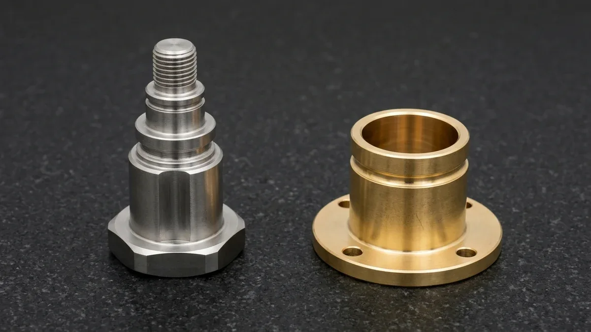
Mastering the core types of turning operations is essential for mechanical engineers designing concentric shafts, threaded fluid fittings, and thin-walled bearing sleeves. In CNC turning, raw cylindrical bar stock rotates inside a spindle chuck or collet while single-point carbide inserts and live driven cutters feed along synchronized X, Z, Y, and C axes.
Unlike multi-flute milling where cutter teeth enter and exit the workpiece intermittently, single-point turning maintains continuous chip engagement across the shear zone. This stable kinematic state enables our Shenzhen CNC turning facility to hold general tolerances to ISO 2768-mK and critical bearing journals within ±0.010 mm to ±0.020 mm (±0.0004″ to ±0.0008″).
Selecting the optimal sequence of external roughing, Constant Surface Speed (G96) facing, radial grooving, single-point threading, and internal boring directly dictates part concentricity and unit cost. Below, our in-house engineering team breaks down the ten primary lathe operations, cutting force physics, boring bar deflection formulas, and shop-floor Design for Manufacturability (DFM) rules.
Executive Summary & Engineering Takeaways (BLUF)
- Ten Core Turning Operations Taxonomy: Modern rotational machining encompasses external straight/step turning, conical taper turning, transverse facing, radial OD/ID grooving, parting-off, single-point threading, internal boring/reaming, coaxial drilling, DIN 82 knurling, and multi-axis Swiss/mill-turn operations.
- Theoretical Roughness Scaling (fn2 vs. rε): Turned surface finish scales quadratically with feed per revolution (fn) and inversely with insert nose radius (rε), delivering Ra 0.4–1.6 µm (16–63 µin) during finish passes without secondary polishing.
- Boring Bar Fourth-Power Stiffness Law: Internal boring bar deflection scales with the cube of overhang (L3) and inversely with the fourth power of bar diameter (dbar4); doubling bar diameter reduces radial deflection by 16 times.
- Turret Chucker vs. Swiss-Type Threshold: Standard turret turning centers efficiently process parts with length-to-diameter ratios L/D ≤ 4:1, whereas slender shafts (4:1 < L/D ≤ 20:1, Ø 0.8–32.0 mm / 0.031–1.260″) require Swiss-type guide-bushing support.
- Ex-Factory Turnaround Benchmarks: Rapid CNC turned prototypes require 4–8 business days ex-factory (7–12 business days with anodizing, passivation, or electroless nickel plating), strictly separated from 3–5 business days international express air transit.
Article Engineering Navigation
- 1. CNC Lathe Kinematics, Cutting Forces & G96 Physics
- 2. External & Planar Turning Operations (Ops 1–3)
- 3. Grooving, Parting, Threading & Internal Holemaking (Ops 4–8)
- 4. Cut Knurling, Mill-Turn & Swiss-Type Turning (Ops 9–10)
- 5. Engineering Matrix of the 10 Turning Operations
- 6. Shop-Floor Execution SOP, Defect Matrix & DFM Rules
- 7. Process Limitations, Trade-Offs & Lead Times
- 8. Technical Engineering FAQ
1. CNC Lathe Kinematics, Cutting Forces & G96 Physics
In all CNC turning operations, the rotating workpiece provides the primary cutting velocity (Vc), while the turret-mounted cutting tool provides linear feed motion. Because chip removal occurs continuously along a helical trajectory, the resultant cutting load decomposes into three orthogonal force vectors acting on the carbide insert tip.
Tangential Cutting Force (Fc) acts downward tangent to the rotating bar surface, accounting for roughly 95% or more of net spindle cutting power (Pc = Fc × Vc). Axial Feed Force (Ff) acts parallel to the Z-axis spindle centerline, resisting longitudinal carriage travel and loading the chuck jaw serrations or collet taper.
Radial Passive Force (Fr) pushes normal to the Z-axis centerline, directly separating the cutting tool and the workpiece. While Fr consumes zero spindle power, it is the primary driver of dimensional error: excessive radial force deflects slender shafts into barrel-shaped tapers and induces regenerative chatter on long internal boring bars.
1. Constant Surface Speed (G96) Spindle Speed, Taper Angle & Volumetric MRR:
n = (1,000 × Vc) ÷ (π × D) | tan(α) = (D1 − D2) ÷ (2L) | MRR = Vc × fn × ap (cm3/min)
2. Theoretical Turned Surface Roughness (Kinematic Cusp Height):
Ra ≈ (fn2 × 1,000) ÷ (32 × rε) | Rz ≈ (fn2 × 1,000) ÷ (8 × rε)
3. Cantilever Workpiece & Boring Bar Radial Deflection:
δradial = (Fr × L3) ÷ (3 × E × I) = (64 × Fr × L3) ÷ (3 × π × E × dbar4)
- n & MRR: Rotational spindle speed in RPM (clamped via
G50 Smax) and volumetric material removal rate in cm3/min (with radial depth of cutapin mm). - Vc & D: Surface cutting speed in m/min (sfm × 0.3048) and instantaneous cutting diameter in mm (in × 25.4).
- fn & rε: Axial/radial feed per revolution in mm/rev (ipr) and insert corner nose radius in mm (typically 0.2, 0.4, or 0.8 mm / 0.008″, 0.016″, or 0.031″).
- δradial, Fr, L, E, I, dbar: Radial deflection (mm), radial passive cutting force (N), unsupported cantilever stickout length (mm), elastic modulus (MPa: 210,000 MPa for alloy steel vs. 600,000 MPa for solid carbide), cylindrical area moment of inertia
I = (π × dbar4) ÷ 64(mm4), and shaft or boring bar diameter (mm).
To illustrate these governing equations on the shop floor, consider finish-turning and boring a 17-4PH stainless steel actuator sleeve with an outer diameter D = 40.0 mm (1.575″) at Vc = 150 m/min (492 sfm). Using the spindle formula, the required rotational speed is n = (1000 × 150) ÷ (3.1416 × 40.0) = 1,194 RPM.
If the external finishing pass uses a DCMT insert with nose radius rε = 0.4 mm (0.016″) at feed fn = 0.10 mm/rev (0.0039 ipr), the theoretical arithmetic roughness is Ra ≈ (0.102 × 1000) ÷ (32 × 0.4) = 0.78 µm (31 µin), with peak-to-valley height Rz ≈ 3.13 µm (123 µin).
For internal boring at Fr = 120 N (27.0 lbf) and L = 80.0 mm (3.150″, 5:1 overhang), a Ø 16.0 mm (0.630″) steel bar (E = 210,000 MPa) deflects by δ = (64 × 120 × 803) ÷ (3 × π × 210,000 × 164) = 0.0303 mm (0.0012″), vs. 0.0106 mm (0.00042″) in solid carbide.
Increasing bar diameter by 25% to dbar = 20.0 mm (0.787″) cuts alloy steel deflection to 0.0124 mm (0.00049″), while upgrading to solid carbide (E = 600,000 MPa) reduces deflection to δ = 0.0043 mm (0.00017″). Because stiffness scales with dbar4, maximizing bore diameter is the highest-leverage DFM rule in internal turning.
2. External & Planar Turning Operations: Straight, Step, Taper & Facing (Ops 1–3)
External and planar toolpaths establish the primary datum geometry of every rotational part. On 2-axis CNC slant-bed turning centers, these three foundational operations remove up to 85% of raw bar stock volume while establishing the coaxial reference journals and perpendicular end faces required for downstream assembly.
Operation 1: External Straight & Step Turning (Roughing vs. Finishing)
External straight turning feeds the cutting insert parallel to the Z-axis spindle centerline to reduce the outer diameter (OD) of the rotating bar into a true cylinder. Step turning repeats this axial pass across progressively smaller target diameters to machine multi-stepped transmission shafts, bearing journals, and locating spigots in a single chucking setup.
Rough straight turning maximizes volumetric material removal (MRR = Vc × fn × ap). Machinists deploy negative-rake 80° rhombic (CNMG) or trigon (WNMG) carbide inserts with a rε = 0.8 mm (0.031″) nose radius, cutting at depths ap = 1.5–4.5 mm (0.059–0.177″) and feeds fn = 0.25–0.40 mm/rev (0.010–0.016 ipr).
Finish step turning leaves a uniform radial stock allowance of 0.20–0.35 mm (0.008–0.014″) for a dedicated spring-pass cutter. Positive-rake 55° (DCMT) or 35° (VBMT) ground inserts with rε = 0.2–0.4 mm (0.008–0.016″) cut at fn = 0.05–0.12 mm/rev (0.002–0.005 ipr) with active tool nose radius compensation (G41/G42) to hold ±0.010 mm (±0.0004″) diameters.
Operation 2: Conical Taper & Contour Profiling
Taper turning generates conical frustums, Morse tapers, and valve seats by driving the X and Z axes simultaneously via linear interpolation (G01) along a half-taper angle tan(α) = (D1 − D2) ÷ (2L). Across conical tapers or spherical transitions (G02/G03), active tool-nose radius compensation (G41/G42) eliminates tangent offset errors and witness steps.
During steep inward taper profiling or back-turning behind a shoulder, insert relief geometry becomes critical. Standard 80° CNMG roughing inserts lack sufficient back clearance and will rub their trailing flank against plunging conical walls, causing severe thermal galling and dimensional distortion.
To prevent trailing-edge interference, CNC programmers switch to high-clearance 35° diamond inserts (VNMG or VBMT) held in neutral or negative-lead holders. Maintaining at least 5° to 7° of physical clearance between the insert flank and the steepest tangent angle of the cone ensures clean shearing across both ascending and descending contours.
Operation 3: Transverse Facing & Datum A Generation
Facing feeds the turning tool radially inward along the X-axis perpendicular to the rotational axis, skimming the raw saw-cut bar end to establish the primary axial length datum (Datum A). Because the cut progresses from the outer perimeter all the way to the centerline (X = 0), cutting diameter approaches zero at the center.
If a lathe executes facing in Constant RPM mode (G97), surface cutting speed drops linearly toward zero as the tool nears X = 0, causing chip welding, built-up edge (BUE), and tearing near the center axis. Therefore, facing always runs under Constant Surface Speed (G96) paired with a safe maximum spindle clamp (e.g., G50 S3500).
Vertical tool center height alignment is equally critical. An insert tip sitting more than 0.03 mm (0.0012″) below the spindle centerline leaves an uncut center nib, whereas mounting above center causes flank rubbing and carbide fracture. Properly centered facing holds end-face perpendicularity within ≤ 0.005 mm (0.0002″).
3. Radial Grooving, Parting-Off, Threading & Internal Holemaking (Ops 4–8)
Once the external envelope and end datum are established, specialized radial and axial tools execute recessed sealing features, helical threads, and concentric internal cavities. These five operations demand strict chip evacuation control because the cutting edge operates inside confined radial slots or deep blind bores.
Operation 4: External & Internal Radial Grooving
Grooving plunges a square-profile or full-radius carbide blade radially along the X-axis (or axially into an end face for face grooving) to machine recessed channels. Common engineering applications include elastomeric O-ring glands per AS568 and ISO 3601, square-shouldered circlip retaining ring grooves per DIN 471 (external) and DIN 472 (internal), and DIN 509 / DIN 76-1 relief undercuts.
Because the front and both side edges of a grooving insert cut simultaneously, radial pressure is high and swarf can wedge against groove sidewalls. Precision grooving inserts incorporate concave top-rake chipformers that curl the ribbon laterally, narrowing chip width by 10%–15% for clean evacuation without scoring critical sealing walls.
Operation 5: Parting-Off (Bar Cut-Off)
Parting-off severs the finished component from parent bar stock using a thin-kerf blade (1.5–3.0 mm / 0.059–0.118″ wide). As the blade approaches the centerline, torsional shear strength at the remaining neck drops below the tangential cutting force, causing premature snap-off and leaving a raised cut-off pip.
On single-spindle chucker lathes, programmers use front-angled (4°–8° lead) parting inserts and reduce X-axis feed by 50%–70% across the final 2.0 mm (0.079″) radius to minimize the witness nib. On twin-spindle centers, a C-axis phase-locked sub-spindle grips the distal end and parts off cleanly with zero center pip.
Operation 6: Single-Point CNC Threading (OD & ID)
Single-point CNC threading cuts external and internal helical threads by synchronizing Z-axis carriage feed with the spindle encoder at 1.0 pitch per revolution (G32/G76). Unlike taps or dies, indexable carbide inserts cut Metric (ISO 965-1 Class 6g/6H), Unified (ASME B1.1 UNC/UNF Class 2A/2B), NPT pipe, and multi-start Acme or Trapezoidal threads across any custom diameter.
Plunging a 60° threading insert radially at 0° infeed forces both flanks to cut simultaneously, trapping V-shaped chips and triggering harmonic chatter. Our programmers specify a 29.5° modified flank infeed across 6 to 18 diminishing constant-area passes, shearing chips cleanly on the leading edge while the trailing edge burnishes the opposite flank.
Operation 7: Internal Boring, Counterboring & Reaming
Internal boring feeds a cantilevered single-point bar into a pre-drilled hole to enlarge the internal diameter (ID), correct drill-walk eccentricity, and cut stepped shoulders, whereas coaxial floating-holder reaming finishes standard H7 dowel bores. Turning the ID and OD in one chucking setup guarantees coaxiality within ≤ 0.005–0.010 mm (0.0002–0.0004″) TIR.
To prevent regenerative chatter governed by the L3 / dbar4 deflection law, shop-floor tooling follows a four-tier overhang hierarchy: alloy steel bars for shallow bores (L/D ≤ 4:1), tungsten heavy metal bars for medium depths (L/D ≤ 6:1), solid carbide bars for extended reaches (L/D ≤ 8:1), and tuned mass-damped bars for deep bores (L/D ≤ 10:1).
Operation 8: Coaxial Spot-Drilling, Peck Drilling & Center-Drilling
Before an internal boring bar can enter a solid bar workpiece, axial holemaking tools mounted in turret ER collets or hydraulic holders open the central core along the Z-axis. Every precision axial hole starts with a stubby 90° or 120° carbide spot drill—or a 60° combined drill-and-countersink (DIN 333 center drill) when the shaft requires tailstock live-center support.
For large diameters (Ø 14.0–40.0 mm / 0.551–1.575″) up to 3×D–4×D depth, indexable carbide U-drills with internal high-pressure coolant channels (3.0–7.0 MPa / 435–1,015 psi) core out the center in a single rapid plunge. Smaller or deeper holes use solid carbide twist drills with G83 peck-retraction cycles to break stringy chips in 304/316L stainless steel and 6061-T6 aluminum.
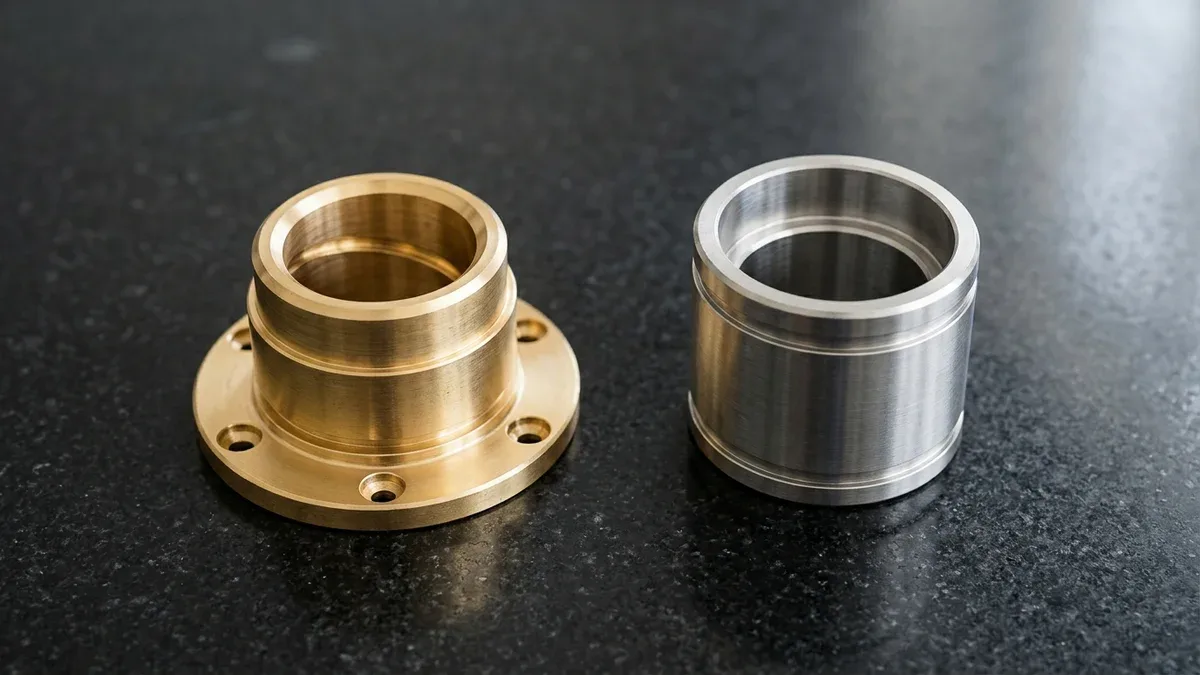
As shown below, combining step turning, facing, internal boring, and radial grooving yields leak-tight bearing sleeves. On the left, a C3604 brass flanged bushing features a bored H7 bearing hole, an internal helical oil groove, and six flange counterbores; on the right, a 316L stainless steel sleeve displays two external O-ring grooves and a stepped internal shoulder.
4. Cut Knurling, Live-Tooling Mill-Turn & Swiss-Type Turning (Ops 9–10)
Modern rotational components rarely consist solely of simple axisymmetric cylinders. To eliminate costly secondary setups on vertical machining centers—where re-clamping a round shaft in a V-block or soft jaw typically introduces 0.015–0.030 mm (0.0006–0.0012″) of stack-up runout—advanced turning centers integrate surface texturing, live rotary milling, and sliding-headstock guide bushings.
Operation 9: Form Knurling vs. Cut Knurling (DIN 82 Patterns)
Knurling generates high-friction grip textures or press-fit serrations around cylindrical collars, thumb screws, and surgical handles. Standardized under DIN 82, common profiles include RAA (straight axial serrations), RBL/RBR (30° left- or right-hand helical knurls), and RGE / RGV (30° diamond patterns with raised or impressed points) across pitches of 0.5–1.6 mm (0.020–0.063″).
A critical distinction separates form knurling (cold plastic displacement) from cut knurling (chip shearing). Form knurling presses hardened rollers into the bar, displacing metal upward and expanding the OD by 0.4–0.5× pitch. However, its extreme radial pressure deflects slender shafts, crushes thin tubes (wall ≤ 2.5 mm / 0.098″), and flakes stainless steels.
To prevent part distortion and surface flaking on medical 303/316L stainless steel, titanium Ti-6Al-4V, and thin-walled aluminum sleeves, our shop deploys twin-wheel cut knurling tools set at an angled shear axis. Cut knurling mills away crisp micro-chips rather than cold-rolling the metal, exerting minimal radial force, preserving internal bore concentricity, and producing razor-sharp diamond or axial serrations.
Operation 10: Live-Tooling Mill-Turn & Swiss-Type Sliding-Headstock Turning
Multi-tasking mill-turn centers pair motorized turret live tooling (end mills, drills, taps, and slitting saws at 4,000–12,000 RPM) with a Servo C-axis spindle and Y-axis slide. In one chucking setup, the machine turns all coaxial diameters and immediately indexes or interpolates to mill wrench flats, keyways, cross-drilled ports, and castle locknut slots.
When part geometry shifts toward slender shafts, bone screws, or micro-pins with length-to-diameter ratios of L/D > 4:1 up to 20:1 and diameters of Ø 0.8–32.0 mm (0.031–1.260″), turret lathes suffer excessive cantilever deflection. For these geometries, Swiss-type CNC machining on Tsugami and Star sliding-headstock lathes is the definitive production solution.
In a Swiss-type lathe, the sliding headstock feeds rotating bar stock along the Z-axis through a stationary tungsten carbide guide bushing. Because gang-slide tools cut within < 1.0 mm (0.5–1.0 mm / 0.020–0.039″) of the bushing face, overhang L approaches zero—eliminating deflection even on Ø 2.0 mm (0.079″) medical endoscopic pins and bone screws.
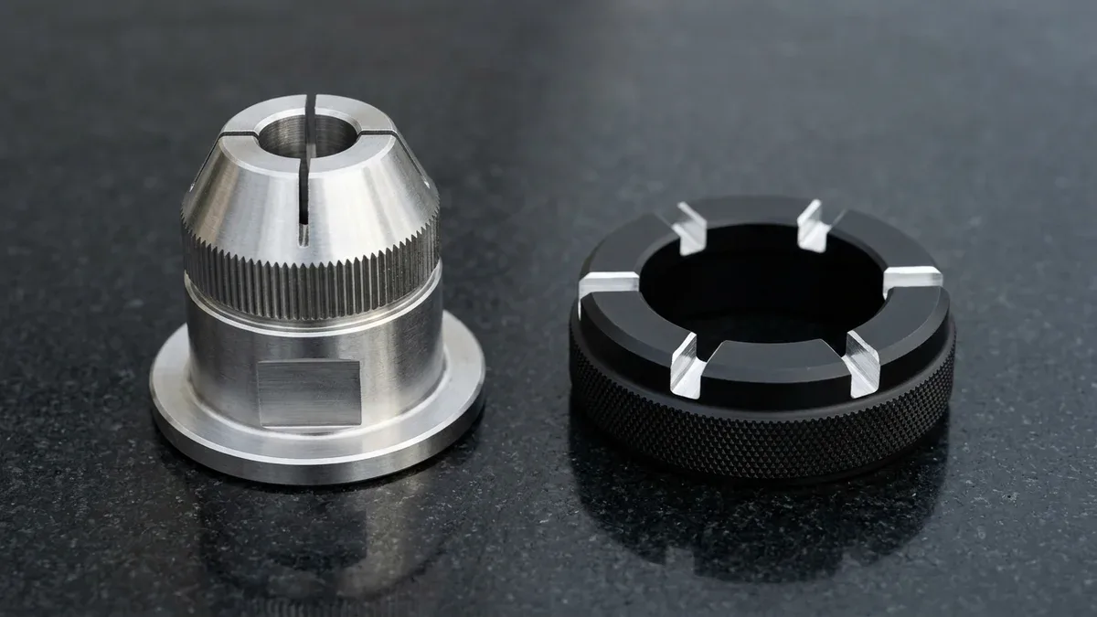
The macro photograph below illustrates cut knurling, taper turning, and live C/Y-axis slotting on turn-mill hardware. On the left, a 303 stainless steel split-collet sleeve displays a straight axial cut-knurled collar, milled wrench flats, and a 20° conical nose with four expansion slots; on the right, a black anodized 6061-T6 castle locknut features diamond knurling and six spanner slots.
5. Comprehensive Engineering Matrix of the 10 CNC Turning Operations
To help hardware engineers select the appropriate lathe kinematics, carbide insert geometries, and realistic drawing callouts during early CAD detailing, the engineering specification matrix below compares all ten core turning operations side by side across cutting feed vectors, achievable dimensional tolerances, surface roughness values, and primary functional applications.
| Turning Operation | Standard Insert / Tool Geometry | Kinematic Feed Vector | Achievable Tolerance & Roughness | Critical Process Control | Recommended Application / When to Choose |
|---|---|---|---|---|---|
| 1. External Straight & Step Turning | 80° CNMG/WNMG (roughing); 55° DCMT / 35° VBMT (finishing, rε = 0.4–0.8 mm) | Axial Z-axis feed parallel to spindle centerline | ±0.010 to ±0.020 mm (±0.0004″ to ±0.0008″); Ra 0.4–1.6 µm (16–63 µin) | G41/G42 nose radius compensation; 0.25 mm uniform finish stock allowance | Choose for external bearing journals, stepped power transmission shafts, and concentric locating spigots. |
| 2. Conical Taper & Contour Turning | 35° VNMG / VBMT high-clearance diamond inserts (≥ 5°–7° back relief) | Simultaneous 2-axis X-Z linear (G01, tan(α) = (D1 − D2) ÷ 2L) or circular (G02/G03) interpolation | Diameter ±0.012 to ±0.025 mm (±0.0005″ to ±0.0010″); surface profile ≤ 0.025 mm; Ra 0.8–1.6 µm (32–63 µin) | G41/G42 tool-nose radius compensation; trailing flank clearance verification (≥ 5°–7°) | Choose for Morse machine tapers, conical collet chucks, fluid valve seats, and aerodynamic nozzle cones. |
| 3. Transverse End Facing | 80° WNMG or 55° DCMT with 95° approach lead angle | Radial X-axis infeed perpendicular to spindle axis down to X = 0 | Perpendicularity ≤ 0.005 mm (0.0002″); length ±0.015 mm; Ra 0.8 µm (32 µin) | Constant Surface Speed (G96) with G50 RPM clamp; Y-center height within ±0.02 mm | Choose for establishing primary axial Datum A surfaces, thrust washer shoulders, and gasket sealing faces. |
| 4. Radial & Axial Grooving | Precision-ground flat or full-radius carbide grooving blades (width 1.0–6.0 mm) | Radial X-axis or axial Z-axis plunge with peck-dwell chip breaking | Groove width ±0.015 to ±0.025 mm (±0.0006″ to ±0.0010″); Ra 0.8–1.6 µm | Chip-narrowing top rake geometry; groove depth-to-width ratio ≤ 3:1 | Choose for AS568 / ISO 3601 O-ring glands, DIN 471/472 circlip grooves, and DIN 509 / DIN 76-1 relief undercuts. |
| 5. Parting-Off (Cut-Off) | Thin-kerf reinforced parting blade (1.5–3.0 mm / 0.059–0.118″) with 4°–8° lead angle | Radial X-axis plunge to spindle centerline or synchronized sub-spindle pick-off | Overall length ±0.025 mm (±0.0010″); Ra 1.6–3.2 µm (63–125 µin) | 50%–70% feed reduction across final 2.0 mm radius; sub-spindle C-axis synchronization | Choose for automated bar-fed separation of finished shafts, pins, and bushings from raw bar stock. |
| 6. Single-Point Threading | 60° (ISO/UN), 55° (BSP), or 29°/30° (Acme/Trapezoidal) laydown carbide inserts | Spindle-encoder synchronized Z-axis multi-pass helical feed (G76 / G32) | ISO 965-1 Class 6g / 6H; ASME B1.1 Class 2A/2B & 3A/3B; pitch diameter ±0.015 mm | 29.5° modified flank infeed with constant-area depth decay; G97 constant RPM | Choose for precision hydraulic ports, thin-wall locknut threads, multi-start lead screws, and large custom threads. |
| 7. Internal Boring & Reaming | Steel (L/D ≤ 4:1), heavy metal (L/D ≤ 6:1), solid carbide (L/D ≤ 8:1), or tuned damped (L/D ≤ 10:1) bars with CCMT/DCMT | Axial Z-axis internal feed inside pre-drilled or cored cavities | ID ±0.010 to ±0.015 mm (H7 fit, ±0.0004″ to ±0.0006″); Ra 0.4–1.6 µm | Maximize bar diameter dbar (δ ∝ 1/dbar4); internal through-tool coolant flushing | Choose for concentric bearing housing bores, stepped sealing sleeves, and hydraulic valve spools. |
| 8. Coaxial Lathe Drilling | 90°/120° spot drill, DIN 333 60° center drill, solid carbide twist drill, or indexable U-drill | Stationary tool feeding axially along Z-axis centerline (X = 0) into rotating bar | Diameter ±0.05 to ±0.10 mm (±0.002″ to ±0.004″); Ra 1.6–3.2 µm | Coaxial turret alignment (≤ 0.01 mm); high-pressure through-coolant (3–7 MPa) | Choose for roughing center through-bores prior to boring and machining 60° tailstock center support dimples. |
| 9. Knurling (Cut vs. Form) | Twin-wheel angled cut-knurling head or straddle form-knurling rollers (DIN 82 RAA / RGE) | Radial engagement + axial Z-axis traverse across external grip band | Pitch 0.5–1.6 mm (0.020–0.063″); OD expansion controlled within ±0.05 mm (cut knurl) | Mandatory cut knurling on thin walls (≤ 2.5 mm) and 303/316L stainless steel; 45° entry chamfers | Choose for thumb adjustment knobs, collet chuck collars, medical handles, and press-fit brass inserts. |
| 10. Mill-Turn & Swiss Turning | Live driven end mills/drills (C/Y/B axes) + tungsten carbide guide bushing (Swiss Ø 0.8–32 mm) | Sliding-headstock Z-feed past guide bushing + synchronized live rotary milling | ±0.010 to ±0.015 mm (±0.0004″ to ±0.0006″); TIR ≤ 0.005 mm; Ra 0.4–0.8 µm | Cutting zone held < 1.0 mm (0.5–1.0 mm) from guide bushing; dual-spindle C-axis phase lock | Choose for slender shafts (L/D > 4:1 up to 20:1) and complex shafts needing wrench flats, cross-holes, and keyways. |
6. Shop-Floor Execution SOP, Defect Matrix & DFM Rules
Achieving tight coaxial concentricity (≤ 0.005–0.010 mm TIR) across multiple CNC machining and turning operations requires disciplined process planning before a bar is loaded into the spindle. At our Shenzhen facility, every precision turned component follows a standardized four-stage shop-floor execution and metrology workflow.
- Verify Raw Bar Stock Alloy & Select Workholding Strategy: Confirm incoming bar material composition via handheld XRF positive material identification (PMI). Select collet chucks or 3-jaw hydraulic chucks for solid shafts (L/D ≤ 3:1), add a rotating tailstock live center for medium shafts (3:1 < L/D ≤ 6:1), machine full-contact contoured aluminum pie jaws for thin-walled rings (wall 0.8–2.0 mm / 0.031–0.079″), or route slender bars (L/D > 4:1, Ø 0.8–32.0 mm) to a Swiss-type sliding-headstock lathe.
- Establish Primary Datum A & Rough Envelope with Balanced Stock Allowance: Face the raw bar end under Constant Surface Speed (G96) with a G50 RPM limit to establish Datum A perpendicularity (≤ 0.005 mm / 0.0002″). Rough external steps and drill/rough-bore internal cavities first so clamping stresses and bulk cutting heat dissipate before any critical finishing pass begins, leaving a uniform 0.20–0.30 mm (0.008–0.012″) radial finish allowance.
- Execute Single-Setup Finish Turning, Boring, Threading & Live Milling: Machine critical H7 internal bores and h6/g6 external bearing journals in the same chucking using positive-rake wiper or ground inserts with active G41/G42 nose radius compensation. Perform 29.5° modified-flank single-point threading, cut knurling, and C/Y-axis live milling of wrench flats or cross-holes prior to synchronized sub-spindle parting-off.
- Conduct In-Process & Final Metrology Verification: Verify external journals inside our 20°C ± 1°C climate-controlled metrology room with precision digital ratchet micrometers (1-micrometer resolution), H7 bearing bores with 3-point self-centering internal bore micrometers calibrated against master setting rings, and threads with calibrated Go/No-Go thread ring and plug gauges. Validate surface roughness (Ra / Rz per ISO 4287 / ASME B46.1) using a diamond-stylus profilometer, and inspect geometric coaxiality and true position on our Zeiss Bridge CMM (available upon request) or 2.5D Optical Vision Measuring System (VMS).
When designing custom turned components in CAD, small geometric oversights—such as sharp 90° internal corners, unsupported deep grooves, or un-relieved thread shoulders—frequently trigger tool chatter or part distortion. The troubleshooting and DFM matrix below pairs the six most common turning defects with their physical root causes and actionable CAD/CAM countermeasures.
| Defect / Machining Failure Mode | Physical & Kinematic Root Cause | Shop-Floor CAM / Tooling Countermeasure | Recommended Application / DFM Design Rule |
|---|---|---|---|
| 1. Mid-Span Barrel Taper on Slender Shafts | Radial passive force (Fr) bows unsupported shaft away from insert at mid-span (δ ∝ L3 / D4). | Switch to 93°–95° lead angle with rε = 0.2 mm positive DCMT insert; support distal end with tailstock live center or route to Swiss guide bushing. | Keep unsupported chucked shaft L/D ≤ 3:1; specify DIN 332 / DIN 333 60° center-drill holes on shafts with L/D between 3:1 and 8:1. |
| 2. Internal Bore Chatter & Bell-Mouth Taper | Excessive boring bar overhang (L/D > 4:1 on steel shank) causes harmonic deflection and chip re-cutting at blind bottom. | Upgrade from steel (L/D ≤ 4:1) to heavy metal (L/D ≤ 6:1), solid carbide (L/D ≤ 8:1), or tuned damped bar (L/D ≤ 10:1); use positive CCMT insert (rε = 0.2 mm) with internal coolant. | Design stepped bores with the largest feasible entry diameter; keep blind bore depth ≤ 5×D and include a 1.5–2.0 mm bottom relief clearance. |
| 3. Trilobular (Out-of-Round) Distortion on Thin Rings | Concentrated radial clamping force from standard 3-jaw chuck elastically deforms thin wall (≤ 2.0 mm); ring springs into a 3-lobed triangle upon release. | Hold part in full-contact 360° contoured aluminum pie jaws or an expanding collet mandrel at reduced hydraulic chuck pressure (0.8–1.2 MPa). | Maintain minimum wall thickness ≥ 1.5 mm (0.059″) on aluminum/stainless sleeves, or add a sacrificial clamping collar that is parted off last. |
| 4. Central Witness Pip & Torn Surface on Faced Ends | Cutting tip set above/below spindle centerline by > 0.03 mm, or facing programmed in G97 constant RPM causing Vc → 0 m/min at X = 0. | Shim or Y-axis adjust tool tip height within ±0.015 mm of spindle axis; program G96 Constant Surface Speed and feed past center to X = −0.8 mm. | Where functional, design a small axial center hole or countersink dimple so the facing insert exits into an open bore rather than a solid core. |
| 5. Torn Thread Flanks & Tool Collision at Shoulder | 0° radial plunge threading overloads both insert edges; lack of thread relief forces abrupt Z-axis deceleration against a 90° vertical shoulder. | Program G76 with 29.5° modified flank infeed and constant chip-area pass schedule, finishing with 1–2 fine spring passes. | Always include a DIN 76-1 thread relief undercut (diameter dg ≈ d − 1.5 × pitch, width per the DIN 76-1 pitch table) at every shoulder termination. |
| 6. Bore Shrinkage & Surface Flaking During Knurling | Form-rolling knurls on thin-walled bushings or 303/316L stainless steel generates extreme radial plastic compression, collapsing the ID bore. | Replace form-rolling knurls with a twin-wheel angled cut-knurling tool; alternatively, finish-bore the critical ID after knurling is complete. | Specify DIN 82 RAA or RGE 30° cut knurling on thin-walled parts (wall ≤ 2.5 mm) and provide 45° entry chamfers on both ends of the knurl band. |
7. When NOT to Choose CNC Turning: Process Limitations, Trade-Offs & Lead Times
While multi-axis CNC turning and mill-turn centers offer remarkable geometric versatility, forcing predominantly non-rotational or extreme-hardness parts onto a lathe leads to excessive cycle times and poor tooling economy. Hardware engineers should evaluate three fundamental process boundaries during early Design for Manufacturability (DFM) reviews:
- Predominantly Prismatic Parts (< 15% Rotational Features): Rectangular enclosures, flat mounting plates, heat-sink cold plates, and multi-pocket structural brackets should not be machined from oversized round bar stock on a mill-turn lathe. High-speed 3-axis and 4-axis vertical machining centers (VMCs) with precision Kurt vises or custom soft jaws provide 3× to 5× higher spindle rigidity and vastly lower material waste.
- Sharp 90° Internal Corners & Blind Square/Hex Broached Sockets: Because every turning and boring insert possesses a physical corner nose radius (rε ≥ 0.1–0.8 mm / 0.004–0.031″), a lathe cannot turn a zero-radius 90° internal shoulder or a sharp-cornered blind square cavity. If a DIN 509 relief undercut or rotary broaching relief hole cannot be added, the feature must transition to Wire EDM (through-profiles) or Sinker EDM (blind cavities).
- Ultra-Tight Grinding Tolerances (±0.005 mm) & Hardened Steels (> 58–60 HRC): While CBN hard turning handles heat-treated alloy steels effectively down to ±0.008 mm (±0.0003″), bearing journals or gauge pins demanding ±0.005 mm (±0.0002″) diametral tolerances and Ra 0.1–0.2 µm (4–8 µin) mirror finishes must be routed to cylindrical or centerless grinding after turning and heat treatment.
For production scheduling, our Shenzhen facility maintains transparent Ex-Factory Production & Inspection Turnaround windows based on complexity and surface finishes. As-machined CNC turned prototypes ship in 4 to 8 business days ex-factory, whereas parts requiring Type II/III anodizing (MIL-A-8625), passivation (ASTM A967), or electroless nickel plating require 7 to 12 business days.
Low-to-mid volume production runs (10 to 1,000+ pieces) on bar-fed turret lathes and Swiss-type centers require 7 to 30 business days ex-factory, including full dimensional and gauge verification. All ex-factory production turnarounds are strictly separated from 3 to 5 business days international express air transit (DHL, FedEx, or UPS) to North American and European engineering facilities.
🔗 Related CNC Turning & Shaft Engineering Guides
8. Technical Engineering FAQ
The ten core CNC turning operations are external straight and step turning, conical taper turning, transverse facing, radial grooving, parting-off, single-point threading, internal boring, coaxial drilling, DIN 82 knurling, and live-tooling or Swiss-type machining. Together, these operations produce concentric shafts, bushings, and threaded fittings in one setup.
Engineers should specify Swiss-type turning whenever slender shafts have a length-to-diameter ratio from 4:1 to 20:1 and an outer diameter of 0.8–32.0 mm (0.031–1.260″). Its stationary tungsten carbide guide bushing supports the bar within 1.0 mm of the tool, holding ±0.010 mm (±0.0004″) tolerances.
Theoretical turned surface roughness follows Ra = (f² × 1000) ÷ (32 × r), scaling with the square of feed per revolution and inversely with insert nose radius. Halving feed from 0.20 to 0.10 mm/rev with a 0.4 mm nose radius reduces theoretical Ra fourfold to 0.78 µm.
Form knurling plastically displaces metal under high radial pressure, crushing thin-walled tubes below 2.5 mm (0.098″) wall thickness and causing flaking on stainless steel. Cut knurling shears crisp micro-chips along an angled axis, minimizing radial force while preserving internal H7 bore roundness and clean DIN 82 serrations.
Ready to Optimize Your Custom Parts for Precision Manufacturing?
Upload your 3D STEP/IGES models and 2D GD&T drawings for a comprehensive CNC turning, live-tooling mill-turn, or Swiss-type manufacturability review from our in-house process engineers. We evaluate bearing journal tolerances, boring bar L/D deflection ratios, and thread relief geometry to optimize concentricity and production efficiency.
Request a Technical DFM & Custom Quote →