

Quick Engineering Takeaways (BLUF)
Metal surface finishing transforms raw CNC machined substrates into functional, corrosion-resistant, and aesthetically refined components. Key mechanical and dimensional design considerations include:
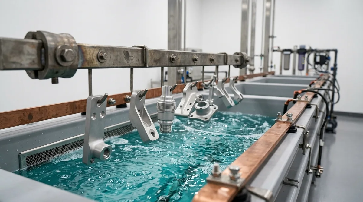
- Anodizing Dimensional Buildup: Type II sulfuric anodizing builds outward by ~5 to 12 μm per surface. Type III hardcoat penetrates 50% into the parent aluminum and grows outward 50% (~25 μm per side for a 50 μm coating), resulting in a ~50 μm (0.0020 in) reduction in internal bore diameters.
- Autocatalytic Plating Uniformity: Electroless Nickel Plating (ENP, ASTM B733) achieves 100% throwing power, depositing an identical thickness across complex blind holes, cross-bores, and internal threads without the corner electric-field crowding (dogbone effect) characteristic of electrolytic hard chrome.
- Corrosion Protection Tiers: High-phosphorus ENP (10–13% P) can exceed 1,000 hours of continuous ASTM B117 salt spray exposure when plated thick enough, while sealed MIL-A-8625 Type II/III anodic coatings are specified at 336 hours (often exceeded). Chemical conversion (MIL-DTL-5541) provides 168+ hours of corrosion barrier while maintaining low electrical contact resistance for RF/EMI grounding.
- Passivation Mechanics: ASTM A967 nitric and citric acid passivation selectively extracts tramp free iron introduced during machining, accelerating the spontaneous formation of a dense, self-healing chromium oxide (Cr2O3) passive layer with zero dimensional change.
- 2D Drawing Best Practice: Always specify whether dimensions apply “before finish” or “after finish.” Clearly designate precision bearing bores and grounding pads for silicone plug masking, and provide a minimum edge radius of R ≥ 0.5 mm to prevent coating burning.
Raw CNC machined components emerge from multi-axis machining centers with distinct geometric textures, microscopic feed marks, and residual surface stresses. While precision cutting achieves tight tolerances down to ±0.010 mm on critical datums, bare metallic alloys remain chemically vulnerable to atmospheric oxidation, galvanic attack, and abrasive wear.
Applying an engineered metal surface finishing system bridges the gap between raw machinability and operational reliability. Selecting the optimal finish requires an in-depth understanding of substrate metallurgy, interfacial adhesion chemistry, and dimensional growth dynamics. For an overview of engineering requirements on machined assemblies, see our comprehensive guide to custom CNC parts.
At AS Prototypes, our dedicated precision finishing department operates alongside our 3-axis, 4-axis, and 5-axis machining centers. In this comprehensive technical guide, our manufacturing engineers evaluate conversion coatings, electrolytic and electroless plating, chemical passivation, and abrasive prep available through our metal surface finishing services and multi-axis precision CNC machining operations to guide your component design decisions.
1. The Metallurgy of Surface Finishing in Precision Manufacturing
Every mechanical component operates under complex environmental and tribological boundary conditions. When a cutting tool shears metal chips during milling or turning, it alters the microstructural properties of the workpiece surface. The shearing action generates microscopic peaks and valleys (quantified by surface roughness parameters Ra, Rz, and Rq), micro-burrs along part edges, and tramp iron contamination from cutting tool contact.
Unprotected aluminum alloys such as 6061-T6 and 7075-T651 naturally form a thin, native oxide film (roughly 2 to 4 nm thick). However, this atmospheric film is thin, non-uniform, and easily destroyed in the presence of chlorides or acidic condensation. Similarly, stainless steels (304, 316L, 17-4PH) rely on an unbroken chromium oxide passive barrier; microscopic iron particles smeared during machining act as galvanic initiation sites that cause severe pitting corrosion.
Modern metal surface finishing processes fall into four major engineering categories:
- Conversion Coatings: Chemical or electrochemical treatments that transform the outermost layers of the base metal into a protective ceramic or oxide compound (e.g., anodizing of aluminum, MIL-DTL-5541 chromate conversion, black oxide on steel).
- Plating Technologies: Additive metal deposition onto the substrate via chemical reduction (electroless nickel) or electric field transfer (electroplating of zinc, copper, or hard chrome).
- Chemical Passivation & Surface Leveling: Controlled chemical dissolution that removes tramp metals, eliminates micro-burrs, and enriches passive alloying elements (e.g., ASTM A967 acid passivation, ASTM B912 electropolishing).
- Mechanical & Abrasive Conditioning: High-velocity media blasting, grain brushing, and precision lapping that modulate surface roughness, induce compressive residual stress, and eliminate directional cutter paths.
To demonstrate the visual and textural transformation across various surface treatment stages, our engineering team regularly produces standardized benchmark specimens for aerospace, medical, and robotics hardware developers.
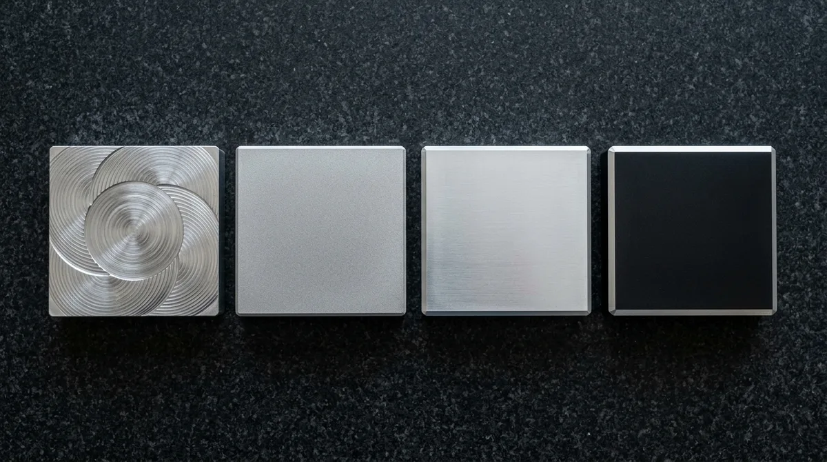
As illustrated above, transitioning from an as-machined milling surface to a fine bead-blasted and anodized state fundamentally alters light reflection, tactile friction, and dielectric insulation. Each subsequent processing tank imposes unique chemical and thermal demands on the workpiece.
2. Anodizing Aluminum: Chemistry, Phase Formation & MIL-A-8625 Standards
Anodizing is an electrolytic passivation process that converts the outer aluminum substrate into an integral, highly ordered hexagonal honeycomb of aluminum oxide (Al2O3). Unlike applied paints or electroplated overlays, an anodic coating is integrated directly with the underlying alloy crystal lattice, preventing flaking, chipping, or delamination under thermal cycling.
During the anodizing reaction, the aluminum workpiece serves as the anode within an acid electrolyte bath, while inert lead or cathode plates complete the circuit. Direct current (DC) drives oxygen ions toward the aluminum surface, causing controlled oxidation:
2Al + 3H2O → Al2O3 + 6H+ + 6e−
Simultaneously, the acidic bath dissolves a fraction of the newly formed oxide, producing millions of microscopic pores per square millimeter. The balance between electrochemical formation and acid dissolution governs the coating density, pore morphology, and mechanical properties according to three standardized classes defined in MIL-A-8625:
MIL-A-8625 Type I & IB: Chromic Acid Anodizing
Type I anodizing uses a chromic acid electrolyte to produce an ultra-thin barrier layer typically between 1.0 μm and 5.0 μm. Because chromic acid does not attack aluminum aggressively, it causes virtually zero reduction in the fatigue endurance limit of high-strength alloys. Aerospace flight-control hardware, structural forgings, and tightly toleranced assemblies frequently specify Type I or Type IB (low-voltage chromic) coatings.
MIL-A-8625 Type II: Sulfuric Acid Anodizing (Class 1 & Class 2)
Type II sulfuric acid anodizing is the most widely utilized finish for commercial and industrial aluminum components. Operated in an 18°C to 22°C sulfuric acid solution with current densities of 1.0 to 1.5 A/dm2, Type II produces an oxide thickness between 10 μm and 25 μm. The process is divided into two primary visual classifications:
- Class 1 (Non-Dyed / Clear): Preserves the natural metallic sheen of aluminum while delivering robust oxidation resistance. It is standard for internal structural chassis, brackets, and enclosures.
- Class 2 (Dyed): Leverages the open hexagonal micro-pores to absorb organic or inorganic colorants (black, blue, red, gold, green) prior to chemical sealing. Sealing in boiling deionized water or hot nickel acetate expands the Al2O3 into hydrated boehmite (Al2O3·H2O), locking in the dye and creating a weather-tight barrier.
MIL-A-8625 Type III: Hardcoat Anodizing
Type III hardcoat anodizing operates under extreme process parameters: chilled sulfuric acid electrolytes maintained between −2°C and 4°C, high tank voltages (up to 75 V), and aggressive current densities (2.0 to 3.5 A/dm2). The low temperature slows down acid chemical redissolution, resulting in a dense, compact cell wall with minimal pore volume.
Hardcoat thickness typically reaches 50 μm (0.0020 in) or greater. The resulting ceramic layer exhibits exceptional microhardness ratings ranging from 400 to 550+ HV0.05 (comparable to case-hardened alloy steel), making it the premier choice for hydraulic actuator cylinders, linear slide rails, pump impellers, and military firearm receivers.
Chemical Conversion Coating: MIL-DTL-5541 (Alodine / Chem Film)
For applications where electrical conductivity or radio frequency (RF) grounding is essential, anodizing cannot be used because aluminum oxide is an electrical insulator (dielectric breakdown voltage > 1,000 V for Type III). Instead, engineers specify chemical conversion coatings conforming to MIL-DTL-5541:
- Type I: Traditional hexavalent chromium formulations (gold/yellow iridite).
- Type II: Modern hexavalent-free, trivalent chromium formulations (clear/iridescent, RoHS and REACH compliant).
- Class 1A: Thicker conversion film optimized for maximum corrosion protection and as a paint bonding primer.
- Class 3: Ultra-thin film engineered specifically for low electrical contact resistance (< 5,000 μΩ/sq in), essential for avionics housings, radar waveguides, and EMI/RFI shielded enclosures.
3. Dimensional Tolerancing, Growth Rules & Masking Strategies
Precision mechanical engineering demands exact mathematical accounting for surface finish thickness. Misunderstanding the geometric growth of anodizing or plating frequently results in undersized bearing bores, jammed dowel pins, and seized thread assemblies.
The fundamental physical law governing aluminum anodizing is the 50/50 Rule of Anodic Growth: the coating consumes parent aluminum for approximately 50% of its total thickness, while building outward into free space for the remaining 50%.
In contrast, additive plating processes (such as electroless nickel, zinc plating, and powder coating) deposit 100% of their thickness onto the exterior boundaries of the workpiece.
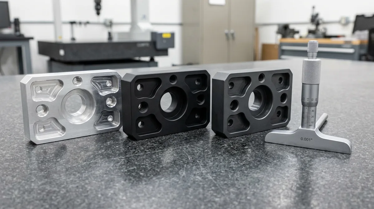
When inspecting post-treatment prototype brackets and housings on precision granite surface plates, our metrology technicians verify these dimensional shifts using calibrated micrometers and bore gauges.
Mathematical Buildup Formulas
To accurately compute finished part dimensions from pre-plating CAD models, apply the following geometric growth formulas:
External Shaft Diameter (Dext) under Anodizing:
ΔDext = +2 × (0.50 × tcoating) = +tcoating
Internal Bore Diameter (Dint) under Anodizing:
ΔDint = −2 × (0.50 × tcoating) = −tcoating
Additive Plating (Electroless Nickel / Zinc Plating):
ΔDext = +2 × tplating
ΔDint = −2 × tplating
For example, if a drawing specifies a 50 μm Type III hardcoat on an aluminum valve manifold, each individual surface grows outward by 25 μm. Consequently, a reamed Ø20.000 mm (+0.010/−0.000 mm) bearing bore will shrink in diameter by exactly 50 μm (0.050 mm), closing down to Ø19.950 mm and failing its fit tolerance.
Thread Pitch Diameter Shift: The 4× Rule
Screw threads represent the most common point of failure when coating buildup is ignored. On standard 60° metric (ISO) and unified (UN/UNC/UNF) threads, coating deposits perpendicularly onto each 30° thread flank. Due to trigonometry, a coating thickness t per surface shifts the theoretical pitch diameter by:
ΔPitch Diameter = 2 × [t / sin(30°)] = 2 × [t / 0.5] = 4 × t
This means an electroless nickel coating of 15 μm will reduce internal thread pitch diameter by 60 μm (0.060 mm), causing standard GO/NO-GO thread plug gauges to bind. Machinists must use oversize taps (e.g., GH3 or GH5 limits) to compensate for planned plating thickness.
Precision Masking Protocols
When engineering requirements forbid coating buildup on critical datums, precision masking is mandatory. Our finishing line utilizes specialized masking techniques:
- Custom Tapered Silicone Plugs: High-temperature (260°C) acid-resistant silicone plugs inserted into reamed dowel holes and threaded blind holes prior to tank immersion.
- Polyimide (Kapton) Die-Cut Tape: Precision cut discs applied to planar grounding pads, mating flange faces, and optical sensor reference surfaces.
- Liquid Masking Lacquers: Hand-applied or robotic-dispensed peelable resists formulated for intricate non-planar geometry, baked and peeled after anodizing.
4. Electroless Nickel Plating (ENP) & Metal Plating Technologies
Unlike conventional electrolytic plating that requires an external power supply and anodes, Electroless Nickel Plating (ENP, ASTM B733) is an autocatalytic chemical reduction process. In an aqueous bath containing nickel salts and sodium hypophosphite, nickel ions deposit evenly onto all catalytically active metal surfaces without electrical current.
This chemical reduction mechanism gives ENP an engineering superpower: 100% throwing power. Electrolytic plating suffers from severe electric-field density variations—current gathers at sharp outer edges (creating excessive bulbous deposits known as “dogboning”) while dropping to near zero inside deep cavities, cross-drilled channels, and blind bores. ENP deposits an identical, micron-uniform thickness across every wetted surface regardless of geometric complexity.
Phosphorus Content Metallurgical Classes
The engineering properties of ENP depend directly on the percentage of co-deposited phosphorus:
- Low-Phosphorus (1–4% P): Produces a microcrystalline deposit with high as-plated hardness (60 to 62 HRC). It provides superior wear resistance and high electrical conductivity, excelling in alkaline operating environments and semiconductor wafer chucks.
- Medium-Phosphorus (6–9% P): The standard industrial workhorse alloy. It balances brightness, moderate corrosion protection, and economical deposition rates for automotive transmission sleeves and robotics links.
- High-Phosphorus (10–13% P): Forms a completely amorphous (glassy, non-crystalline) structure with zero magnetic permeability (μ ≤ 1.005). The absence of grain boundaries prevents galvanic pathway formation, delivering extraordinary corrosion endurance exceeding 1,000 hours in ASTM B117 salt fog. It is widely specified in oil & gas subsea manifolds and aerospace fuel systems.
Thermal Post-Baking: Precipitation Hardening to 70 HRC
As-plated ENP achieves a hardness of 48 to 52 HRC (medium/high phos). By subjecting the plated component to a heat treatment cycle of 400°C for 1 hour in a protective atmosphere furnace, fine intermetallic nickel phosphide (Ni3P) precipitates throughout the matrix. This precipitation hardening cycle elevates coating hardness to 68 to 70 HRC (steel and stainless substrates only; heat-treatable aluminum such as 6061-T6 or 7075 cannot be baked at 400°C without losing temper), directly matching the abrasion resistance of hard industrial chrome plating while eliminating hexavalent chromium environmental hazards.
Alternative Plating Technologies
Depending on functional demands, other plating methods provide targeted benefits:
- Hard Chrome Plating (AMS 2460): Heavy electrolytic deposition (25 to 250 μm) with an exceptionally low dynamic coefficient of friction (0.15 unlubricated). Essential for hydraulic cylinder rods, printing rollers, and heavy extrusion dies.
- Zinc Plating with Trivalent Passivation (ASTM B633): Sacrificial cathodic protection for carbon steel chassis, brackets, and fasteners. Available in clear (blue-bright), yellow, or black trivalent chromates conforming to RoHS regulations.
- Gold & Silver Plating (ASTM B488 / ASTM B700): Noble metal coatings applied over an ENP underplate for high-frequency electrical contacts, spaceflight optics, and wire bonding pads.
5. Chemical Passivation, Electropolishing & Steel Surface Treatments
Precision stainless steel parts utilized in surgical instruments, cleanroom automation, and semiconductor fluid handling require meticulous surface purification to prevent corrosion.
Stainless Steel Passivation: ASTM A967 & AMS 2700
During milling and turning operations on austenitic (304, 316L) or martensitic/precipitation-hardening (440C, 17-4PH) stainless steels, microscopic particles of tool steel from carbide end mills and work-holding fixtures become mechanically embedded into the workpiece surface. In humid air, these “tramp iron” particles oxidize rapidly, establishing micro-galvanic cells that rupture the surrounding stainless matrix.
Passivation conforms to ASTM A967 (or aerospace standard AMS 2700) using two chemical acid methodologies:
- Nitric Acid Passivation (Practice Nitric 1 to 5): Traditional formulation utilizing 20% to 50% nitric acid with optional sodium dichromate oxidizers. Nitric acid aggressively dissolves free iron and drives instant oxidation of surface chromium. However, it poses severe environmental hazards and can cause “flash attack” pitting on high-carbon grades if bath chemistry shifts.
- Citric Acid Passivation (Practice Citric 1 to 5): Modern organic formulation that utilizes targeted chelation chemistry. Citric acid molecules selectively bind and remove iron ions while leaving chromium, nickel, and molybdenum undisturbed. It is environmentally safe, non-hazardous, and achieves a chromium-to-iron (Cr/Fe) surface ratio exceeding 2.0.
Passivated components undergo strict quality verification, including 24-hour high-humidity testing, copper sulfate testing, and 2-hour water immersion testing to confirm complete absence of free iron.
Electropolishing: ASTM B912
Electropolishing is an electrochemical process often described as “reverse electroplating.” The stainless steel workpiece is submerged in a concentrated sulfuric and phosphoric acid electrolyte and connected to the positive DC terminal. The electrical current density concentrates heavily at microscopic surface peaks, burrs, and sharp ridges.
By selectively dissolving micro-peaks at a faster rate than micro-valleys, electropolishing achieves three critical milestones:
- Reduces surface roughness by 50% or more (e.g., dropping an as-machined Ra 0.8 μm down to Ra 0.2 μm).
- Eliminates microscopic burrs, tool tears, and micro-cracks that initiate mechanical fatigue failure.
- Dramatically enriches the surface Cr/Fe ratio (often exceeding 2.5:1), establishing the highest possible biocompatibility and cleanroom ultra-high vacuum (UHV) outgassing resistance.
Black Oxide Conversion: MIL-DTL-13924
For alloy steels (4140, 4340, 1045), tool steels, and copper alloys requiring a non-reflective matte black finish with zero dimensional change (< 0.5 μm), hot black oxide conversion is the standard. Operating in a caustic alkaline bath at 140°C, the chemical solution converts surface iron into magnetite (Fe3O4). Because black oxide possesses minimal standalone corrosion resistance, parts are post-dipped in water-displacing rust preventative oils or dry-to-the-touch waxes.
6. Mechanical Surface Preparation: Bead Blasting, Brushing & Polishing
Prior to chemical tank immersion, mechanical surface preparation creates the foundation for cosmetic appearance and coating adhesion. Abrasive conditioning removes directional machining tool lines, deburrs complex profiles, and modifies surface energy.
Bead Blasting Dynamics
Bead blasting utilizes compressed air (0.3 to 0.5 MPa) to propel spherical media against the component surface. The impact produces millions of micro-craters, creating an isotropic, non-directional satin matte finish:
- Coarse Glass Beads (#80): Media diameter ~180 to 250 μm. Yields a textured satin finish with Ra 1.6 to 2.4 μm. Ideal for rugged industrial enclosures, heavy heatsinks, and concealing deep milling toolpath overlap.
- Fine Glass Beads (#120): Media diameter ~100 to 150 μm. Delivers a silky, smooth matte sheen with Ra 0.8 to 1.4 μm. This is the optimal pre-treatment before Type II color anodizing, ensuring uniform dye saturation without hot spots.
- Ceramic Bead Blasting (Zirblast): Ceramic zirconia beads offer exceptional shatter resistance and zero metallic contamination. They produce an ultra-consistent satin finish on medical hardware and titanium components.
DFM Precaution: Thin-walled sheet metal housings or milled webs thinner than 1.0 mm can suffer severe dimensional warpage from compressive residual stresses induced by aggressive bead blasting. Machinists must reduce blast pressure and fixture thin walls during processing.
Directional Linear Brushing
Linear grain brushing utilizes automated abrasive Scotch-Brite drums or grit belts (#180 to #320 grit) to generate continuous parallel striations across flat panels. It is widely specified for premium consumer electronics faceplates, audio amplifier chassis, and architectural stainless trim, creating an unmistakable brushed-metal aesthetic.
Precision Optical Polishing & SPI Mold Standards
For optical reflectors, light guides, and plastic injection mold inserts, mechanical hand polishing progresses through descending grit silicon carbide papers and diamond paste compounds. Standard finishes align with the Plastics Industry Association (SPI) guidelines:
- SPI A-1: Grade #3 diamond buffing paste (Ra < 0.02 μm) for high-gloss optical mirror clarity.
- SPI A-2: Grade #6 diamond paste (Ra 0.02 to 0.05 μm) for clear lens tooling.
- SPI B-1: 600-grit paper polish (Ra 0.05 to 0.10 μm) for semi-gloss cosmetic parts.
7. Quality Control, Metrology & NDT Verification
Ensuring that post-finishing components satisfy rigorous aerospace and medical standards requires comprehensive metrology and non-destructive testing (NDT). In our climate-controlled inspection lab, quality engineers deploy calibrated analytical instruments to verify coating parameters.
To measure non-conductive anodic oxide layers on aluminum without scratching the finished part, our technicians utilize digital eddy-current thickness gauges calibrated to traceable foil standards.
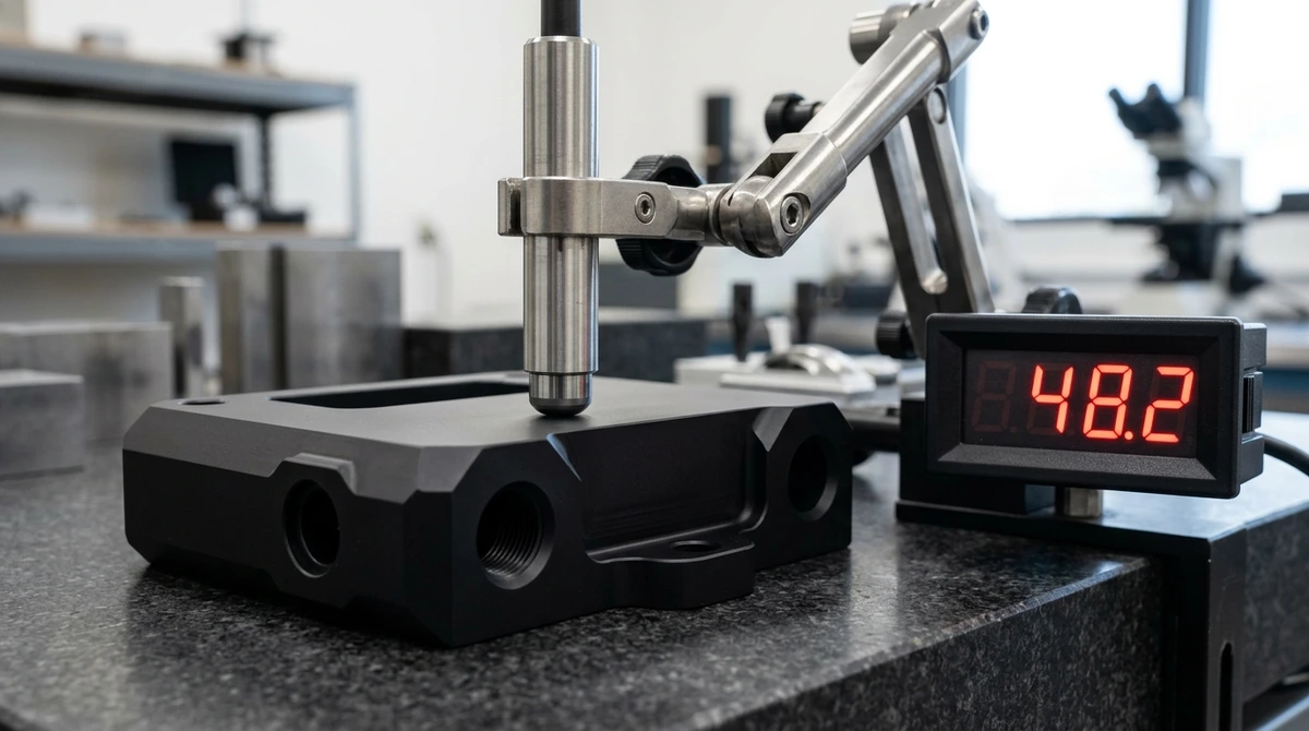
Our quality verification protocol encompasses five core test methodologies:
- Eddy-Current Coating Thickness (ISO 2360 / ASTM B244): Employs high-frequency electromagnetic probe excitation to measure non-conductive coatings (anodize, paint, powder) over non-magnetic base metals (aluminum, brass) with sub-micron resolution.
- Magnetic Induction Testing (ISO 2178 / ASTM B499): Uses magnetic flux density sensors to quantify non-magnetic coatings (electroless nickel, zinc, chrome) deposited onto ferromagnetic steel substrates.
- Cross-Hatch Adhesion Tape Test (ASTM D3359 Method B): Precision 1 mm or 2 mm lattice cutting grid applied with pressure-sensitive tape peel to confirm zero inter-coat delamination on paints, primers, and thermal coatings.
- Neutral Salt Spray Testing (ASTM B117 / ISO 9227): Accelerated environmental chamber exposing components to continuous 5% NaCl atomized mist at 35°C. Validates corrosion resistance over durations ranging from 24 hours (black oxide) to 336 hours (Type II anodize) and 1,000+ hours (high-phos ENP, thick deposits); sealed Type III hardcoat is specified at 336+ hours.
- Optical Profilometry (ISO 4287 / ASME B46.1): Contact diamond stylus and non-contact white light interferometry systems to verify surface texture parameters (Ra, Rz, Rmax) before and after mechanical processing. For comprehensive parameter definitions and evaluation cut-offs, consult our detailed reference on surface texture and roughness standards.
8. Engineering Comparison & Selection Matrices
To assist design engineers in choosing the most effective surface treatment for specific operating environments, our engineering group has compiled the following multi-criteria comparison matrices.
Table 1: Comprehensive Metal Surface Finishing Engineering Matrix
| Finishing Process | Target Substrate | Coating Thickness Buildup | Surface Hardness | Corrosion Resistance (ASTM B117) | Primary Engineering Application |
|---|---|---|---|---|---|
| Type II Anodizing (MIL-A-8625) | Aluminum (6061, 7075, 5052) | 10 to 25 μm (50% in / 50% out) | 250 to 350 HV0.05 | High (336+ hrs NSS) | Cosmetic front panels, electronic housings, non-conductive brackets. |
| Type III Hardcoat (MIL-A-8625) | Aluminum (6061, 7075) | 50 μm (50% in / 50% out) | 400 to 550+ HV0.05 | Very High (336+ hrs NSS, sealed) | Hydraulic cylinders, aerospace sliding rails, robotics bearing journals. |
| Chem Film / Alodine (MIL-DTL-5541) | Aluminum Alloys | Sub-micron (< 1.0 μm) | Same as substrate | Moderate (168+ hrs NSS) | Electrical grounding enclosures, RF shielding, paint primer base. |
| Electroless Nickel (ASTM B733) | Steel, Aluminum, Copper, Brass | 5 to 50 μm (100% additive) | 48–52 HRC (Baked: 68–70 HRC) | Superior (1,000+ hrs for high-P) | Fluid manifolds, valve spools, internal bores, harsh subsea hardware. |
| Stainless Passivation (ASTM A967) | Stainless (304, 316, 17-4PH) | Zero dimensional change | Same as substrate | Enriched Cr2O3 barrier | Surgical instruments, semiconductor hardware, marine shafts. |
| Electropolishing (ASTM B912) | Stainless Steel, Titanium | Subtractive (−5 to −15 μm) | Same as substrate | Maximum passivity | Pharmaceutical cleanrooms, UHV chambers, bio-implant surfaces. |
| Black Oxide (MIL-DTL-13924) | Carbon Steel, Alloy Steel | < 0.5 μm (Negligible) | Same as substrate | Low (Requires oil/wax dip) | Tooling fixtures, precision machine gages, non-reflective optical parts. |
Table 2: Dimensional Compensation & Feature Impact Guide
| Finishing Process | Nominal Coating Thickness | External OD Growth | Internal Bore Shrinkage | Thread Pitch Diameter Shift | DFM Masking Recommendation |
|---|---|---|---|---|---|
| Type II Anodize | 15 μm (0.0006 in) | +15 μm (+0.0006 in) | −15 μm (−0.0006 in) | 30 μm shift (4 × 7.5 μm build) | Mask reamed bores < Ø6 mm or tap threads with GH3 limits. |
| Type III Hardcoat | 50 μm (0.0020 in) | +50 μm (+0.0020 in) | −50 μm (−0.0020 in) | 100 μm shift (4 × 25 μm build) | Always plug bearing bores and threaded holes with silicone caps. |
| Electroless Nickel | 20 μm (0.0008 in) | +40 μm (+0.0016 in) | −40 μm (−0.0016 in) | 80 μm shift (4 × 20 μm build) | Machine bores 40 μm oversize prior to plating tank immersion. |
| Passivation | Molecular film (< 5 nm) | 0.000 mm | 0.000 mm | 0.000 mm | No masking required; fully safe for finished precision threads. |
Table 3: Mechanical Prep & Surface Roughness Progression
| Mechanical Treatment | Abrasive Media / Tooling | Typical Roughness (Ra) | Visual Appearance | Key DFM Role |
|---|---|---|---|---|
| As-Machined (Milled) | Solid Carbide Face Mill | Ra 0.8 to 1.6 μm | Directional cutter paths | Standard baseline finish for internal structural components. |
| Bead Blast (#80 Coarse) | Glass Beads (180–250 μm) | Ra 1.6 to 2.4 μm | Coarse satin matte | Conceals heavy tool marks and provides mechanical grip. |
| Bead Blast (#120 Fine) | Glass Beads (100–150 μm) | Ra 0.8 to 1.4 μm | Fine uniform satin | Mandatory pre-treatment for flawless cosmetic dyed anodizing. |
| Linear Brushing | Scotch-Brite / Grit Belts | Ra 0.4 to 0.8 μm | Directional brushed grain | Premium consumer electronics front panels and audio housings. |
| Electropolishing | Sulfuric / Phosphoric Bath | Ra 0.1 to 0.2 μm | Ultra-bright mirror luster | Removes micro-burrs and eliminates particulate traps for cleanrooms. |
9. DFM Best Practices for 2D Engineering Drawings
Clear communication between design engineering and the manufacturing floor prevents costly rework, scrapped batches, and delayed delivery schedules. When releasing CAD models and 2D engineering drawings for metal finishing, observe five essential DFM rules:
1. Standardize Callout Terminology
Avoid ambiguous drawing notes such as “Anodize black” or “Nickel plate.” Explicitly reference recognized international specifications, type, and class. For example:
- Preferred Anodize Callout: “MIL-A-8625, Type III, Class 2 (Black), 50 μm ± 10 μm coating thickness. Dimensions apply AFTER finish.”
- Preferred Plating Callout: “ASTM B733, Type V (High-Phosphorus), Class 1, 25 μm coating thickness. Post-bake 190°C for 3 hours for hydrogen embrittlement relief.”
- Preferred Passivation Callout: “ASTM A967, Practice Citric 2. Test per Section 14 (Copper Sulfate).”
2. Specify Dimension Precedence
State unambiguously whether linear and diameter tolerances apply BEFORE FINISH or AFTER FINISH. In the absence of a note, precision CNC machine shops generally measure parts in the raw machined state, which leads to oversized assemblies once 50 μm of hardcoat or plating is added.
3. Provide Corner Edge Radii (Break Sharp Edges)
In both electrolytic anodizing and electroplating tanks, electric current concentrates intensely at sharp 90° corners. This high current density causes “burning”—producing brittle, powdery, or flaking deposits that readily chip off during handling. Furthermore, surface tension in plating baths pulls liquid away from knife edges, resulting in thin coverage. Always model or call out a minimum edge break or blend radius of R ≥ 0.5 mm (0.020 in) on all external corners. For complementary design rules on internal pocket radii and corner relief notches, review our manufacturing guide to sharp corners in CNC machining.
4. Plan for Racking & Electrical Contact Points
Workpieces cannot float freely in anodizing or plating tanks; they must be clamped securely to titanium or aluminum electrical racks. The clamping contact point leaves a small un-coated or un-dyed void roughly 1 to 2 mm in size. In your 2D drawings, include a note specifying permissible clamping zones (e.g., “Racking marks permitted on interior non-cosmetic surfaces only”) or design dedicated sacrificial threaded holes for racking fixtures.
5. Prevent Air and Liquid Trapping in Blind Holes
Deep blind holes with high aspect ratios (> 3:1) trap air pockets during tank immersion, preventing anodizing solutions from contacting the bottom surfaces. Conversely, aggressive acid solutions can become trapped inside blind bores during rinse cycles, bleeding out days later and causing localized corrosion bloom. Whenever possible, design cross-drilled relief holes or permit un-anodized conditions inside deep blind cavities.
MIL-A-8625 Type III hardcoat penetrates 50% into the parent aluminum and builds outward 50%. A standard 50 μm hardcoat adds 25 μm per surface, reducing internal bore diameters by 50 μm (0.0020 in). Thread pitch diameters shrink by approximately 4 times the single-surface growth (roughly 100 μm). Precision bearing bores and threads must be protected with custom silicone masking plugs or machined oversize prior to tank immersion.
Standard electrolytic nickel requires an electric current and external anodes, which causes current density crowding at sharp edges (dogbone buildup) and inadequate coverage in deep cavities. Electroless Nickel Plating (ASTM B733) is an autocatalytic chemical reduction process with 100% throwing power, depositing an identical, uniform thickness across exterior faces, blind holes, cross-bores, and internal threads.
Yes. Standard sulfuric and hardcoat anodizing form an aluminum oxide ceramic barrier that acts as an electrical insulator. To preserve electrical grounding and EMI/RFI shielding, engineers specify MIL-DTL-5541 chemical conversion coating (Alodine / Chem Film, Class 3), which produces an ultra-thin sub-micron barrier with surface contact resistance under 5,000 μΩ/sq in.
During CNC milling and turning, carbide end mills, steel collets, and work-holding vises embed microscopic particles of free iron into the stainless steel surface. In the presence of moisture, these free iron particles corrode rapidly, destroying the surrounding material. Chemical passivation per ASTM A967 dissolves this free iron and accelerates the spontaneous formation of a pure, continuous chromium oxide protective film.
Designers should provide a minimum corner edge break or radius of R ≥ 0.5 mm (0.020 in) on all exterior edges. Sharp 90° corners cause severe electric-field concentration, leading to brittle coating burning, uneven thickness buildup, and edge flaking during assembly.
Ready to Elevate Your Machined Parts with Precision Surface Finishing?
Our in-house CNC machining and surface finishing facilities provide tightly integrated manufacturing—from rapid prototyping to low-to-medium volume production. Upload your 3D CAD models and 2D engineering drawings for a comprehensive DFM review and detailed quote within 24 hours.
Request CNC & Finishing Quote






