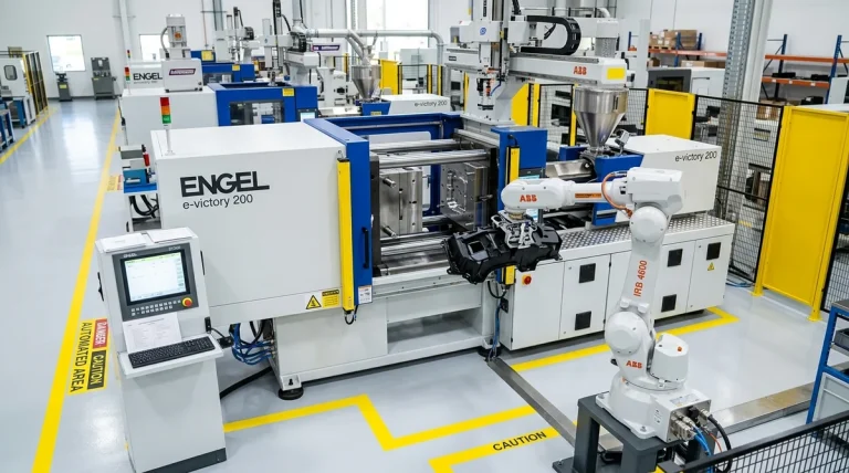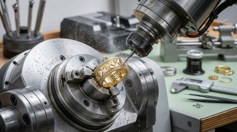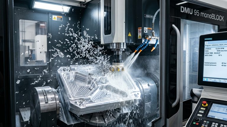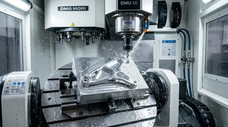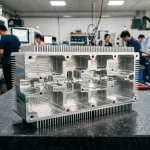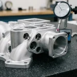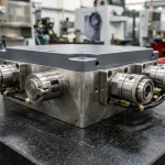
Designing an electronic enclosure that looks sleek on a 3D CAD screen is straightforward; engineering that same enclosure to survive sub-surface hydrostatic pressure, torrential rainstorms, chemical washdowns, and thermal expansion cycling without a single drop of water entering the PCB chamber is an entirely different caliber of engineering. Whether developing an outdoor IoT environmental sensor, an industrial telemetry beacon, a rugged military-grade handheld device, or a submersible marine controller, hermetic sealing integrity cannot be treated as an afterthought.
In rapid prototyping, engineers often face severe dilemmas: standard 3D printed parts leak through microscopic layer voids, off-the-shelf catalog enclosures rarely fit custom internal battery packs or antenna layouts, and improper gasket gland geometries lead to pinching, permanent compression set, or catastrophic joint blowout under clamping loads. Achieving a verified IP67 or IP68 rating in the prototype stage requires a holistic synthesis of elastomeric material science, precision gland mechanics, and rigorous non-destructive leak metrology.
In this comprehensive engineering guide, AS Prototypes deconstructs the foundational physics of ingress protection, calculates precision O-ring compression kinematics, evaluates 5 practical enclosure sealing technologies, and outlines the rapid prototyping pathways required to transition your sealed enclosure from design validation into volume production.
Demystifying Ingress Protection: IP Ratings vs. Real-World Hydrostatic Forces
Ingress Protection (IP) ratings are governed internationally by IEC 60529 (and harmonized under EN 60529 / ANSI standards), categorizing enclosure resilience against solid particulate intrusion (first digit) and liquid ingress (second digit). In rugged electronic applications, the liquid ingress ratings dictate the mechanical sealing architecture:
- IP65 (Water Jets): Enclosure is dust-tight and shielded against low-pressure water jets (6.3 mm nozzle, 12.5 L/min at 30 kPa) projected from any direction. Typical sealing: flat die-cut silicone gaskets or simple continuous elastomeric cords.
- IP66 (Powerful Water Jets): Dust-tight protection against high-pressure water jets (12.5 mm nozzle, 100 L/min at 100 kPa) simulating heavy seas or direct industrial power washdowns. Demands tongue-and-groove glands to prevent gasket unseating under directional hydraulic blast.
- IP67 (Temporary Immersion): Dust-tight protection against submersion in water up to 1 meter depth for 30 minutes. The hydrostatic pressure differential is approximately 0.1 bar (1.45 psi). Requires calculated elastomeric compression (20% to 30%) with continuous mechanical clamping.
- IP68 (Continuous Hydrostatic Submersion): Dust-tight protection under continuous submersion beyond 1 meter under parameters explicitly specified by the manufacturer (typically 1.5 m to 5 m for 2 hours, or depths exceeding 10 m in specialized marine electronics). Hydrostatic pressures easily exceed 0.5 to 1.0 bar, necessitating rigid structural wall reinforcement to eliminate housing deflection.
- NEMA 4X / 6P Equivalency: Beyond pure water ingress, North American NEMA ratings factor in environmental extremes—including corrosion resistance, ambient thermal cycling (-40°C to +85°C), ice formation, and UV radiation stability.
Elastomeric Gland Design: Core Mechanics & Geometry Rules
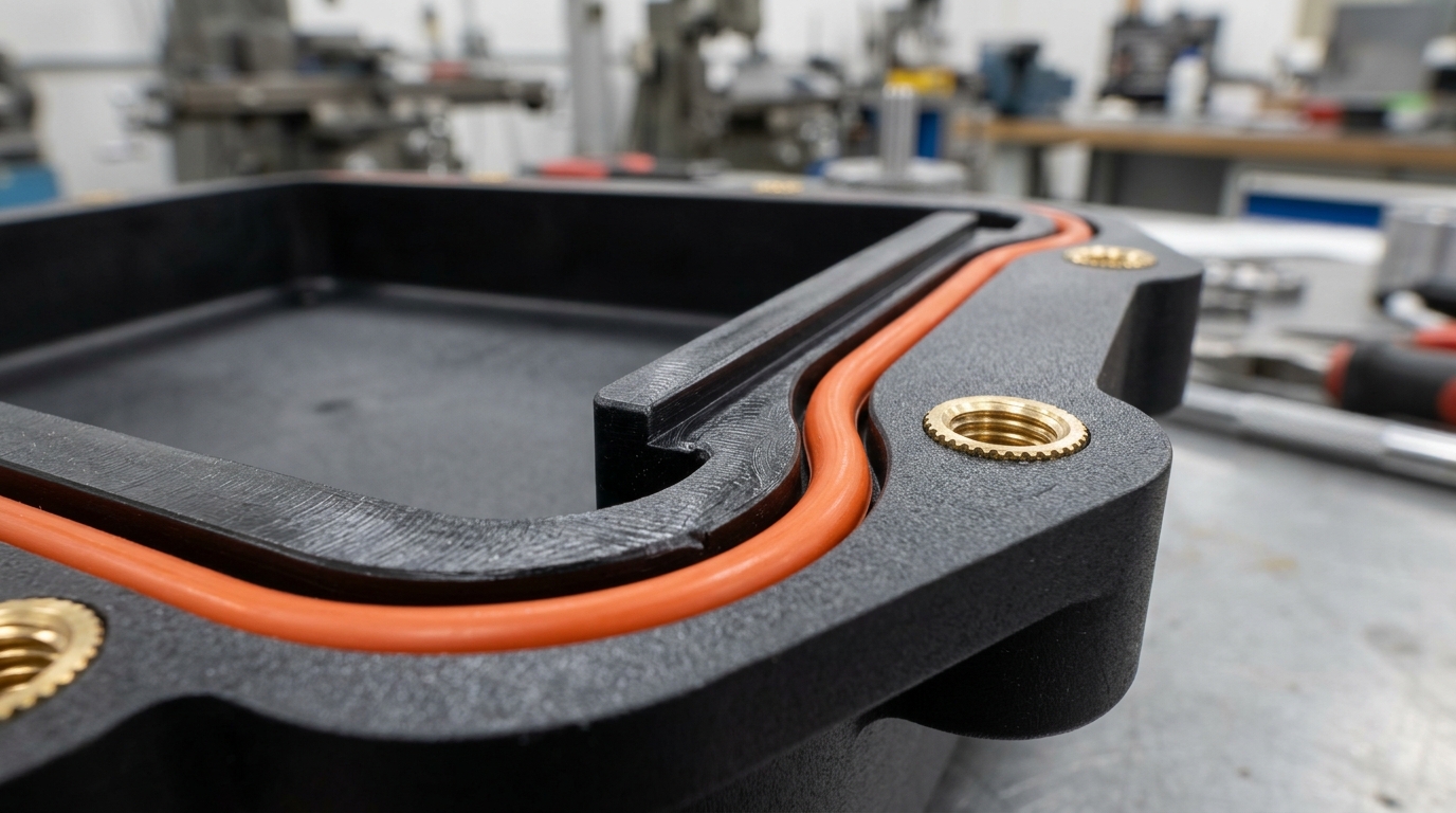
The vast majority of waterproof enclosure prototype failures trace directly back to improper gasket gland geometry or uncontrolled flange deflection. An elastomer seals by behaving like an incompressible fluid: when compressed between two rigid mating housings, it exerts continuous elastic contact stress against the gland walls. If that contact stress exceeds the external fluid pressure, ingress is physically blocked. To engineer a leak-proof static seal, design engineers must master four non-negotiable geometric variables:
1. Compression Ratio (Squeeze Percentage)
The squeeze ratio is defined as the reduction in the cross-sectional diameter of the elastomer divided by its original nominal cross-section ((d - h) / d * 100%). For static plastic enclosure seals:
- Recommended Static Range: 20% to 30% squeeze. Less than 15% risks inadequate contact stress under dynamic vibration or thermal shrinkage; greater than 35% induces excessive shear stress, accelerated permanent compression set, and severe assembly friction that twists the O-ring.
- Durometer Pairing: Softer elastomers (40 to 50 Shore A silicone) conform readily to subtle prototype surface variations with low clamping force, whereas firmer compounds (70 Shore A Viton or NBR) offer superior extrusion resistance at elevated pressures.
2. Gland Volume Fill Ratio
Elastomers are virtually incompressible; when squeezed vertically, they expand laterally. A catastrophic design flaw is designing the gland width exactly equal to the compressed O-ring footprint:
- Maximum Volume Fill Limit: The cross-sectional area of the uncompressed O-ring should never exceed 75% to 85% of the rectangular gland cross-sectional area.
- Thermal & Chemical Clearance: Reserving 15% to 25% void volume within the gland channel prevents “gland overfill” (hydrostatic blowout) caused by elastomer thermal volumetric expansion or chemical solvent swelling.
3. Surface Finish in the Sealing Channel
Under hydrostatic head pressure, micro-grooves and tooling chatter marks become capillary conduits for moisture intrusion. In CNC-machined prototype housings, the sealing gland channel should maintain an Ra surface roughness of 0.8 μm (32 μin) or better. Radial tool drag marks perpendicular to the sealing line must be eliminated by utilizing continuous trochoidal high-speed ball-end milling paths or fine bead blasting.
4. Clamping Flange Stiffness & Screw Pitch Optimization
In plastic enclosures, the structural housing flexes between fastener locations. If screw spacing is too wide, the housing cover acts as an unsupported beam, bowing upward between screws and dropping gasket compression below the critical sealing threshold:
- Beam Deflection Control: Position perimeter screw bosses so that maximum span between fasteners does not exceed 30 mm to 50 mm, depending on cover wall thickness.
- Threaded Fastening Integrity: Never drive self-tapping sheet metal screws directly into raw thermoplastic bosses for waterproof prototypes; repeated torque relaxation will destroy seal preload. Instead, specify ultrasonically welded or heat-set brass threaded inserts (M2.5 or M3) capable of sustaining consistent torque specifications (0.4 to 0.8 Nm) without stripping.
5 Sealing Technologies for Plastic Prototype Enclosures
Choosing the optimal sealing process depends directly on production volume, enclosure complexity, IP target, and whether the device must be field-serviceable. Below are the 5 mainstream industrial methodologies deployed at AS Prototypes:
1. Molded or Extruded Continuous Silicone O-Rings
The gold standard for modular, serviceable enclosures. Custom O-rings can be molded from liquid silicone rubber (LSR) via aluminum prototype tooling or spliced from extruded precision elastomeric cords. They deliver proven temperature resilience (-50°C to +200°C), low compression set, and straightforward replacement during field battery servicing.
2. 2K Dual-Shot Injection Overmolding (Rigid Substrate + TPE)
In high-performance handheld or consumer electronic devices, manual gasket installation is eliminated by chemically bonding a soft thermoplastic elastomer (TPE, 40–60 Shore A) directly onto the rigid housing perimeter (polycarbonate, ABS, or PBT) during a two-shot injection molding cycle. Overmolding prevents gasket roll-out, reduces assembly labor to zero, and achieves seamless IP68 ingress protection. For prototype stages, AS Prototypes utilizes rapid shuttle-insert molds to validate 2K overmolded seals before committing to multi-cavity rotary tooling.
3. Liquid Dispensed Cured-In-Place Gaskets (CIPG / FIPG)
Cured-in-Place Gasketing (CIPG) and Form-in-Place Gasketing (FIPG) utilize a multi-axis robotic dispensing head to lay down a precise micro-bead of room-temperature vulcanizing (RTV) silicone or UV-curable polyurethane into a shallow housing groove. The liquid bead conforms intimately to complex 3D non-planar contours, eliminating manual handling. CIPG adheres permanently to one side of the housing while curing into a resilient compressible seal.
4. Polyurethane Vacuum Casting with Co-Molded Elastomers
When prototyping pre-production batches (10 to 50 units) without paying for steel injection molds, silicone vacuum casting is an unbeatable process. Enclosure housings can be cast in ABS-like or PC-like polyurethanes, and elastomeric seals can be co-cast or insert-molded directly in soft polyurethane (Shore 45A–60A) in the exact same silicone master mold.
5. Ultrasonic & Laser Plastic Welding (Permanent Hermetic Seals)
For disposable medical devices, non-rechargeable sensors, or subsea transponders where internal battery access is unnecessary, mechanical fasteners and gaskets can be omitted entirely. Utilizing an ultrasonic welding energy director (a 60° triangular ridge molded along the joint seam) or infrared laser plastic welding, the mating housing halves melt and fuse at the molecular level, creating a permanent, 100% hermetic joint impervious to gas and water ingress.
Engineering Comparison: Sealing Methods for Plastic Enclosures
| Sealing Technology | Achievable Ingress Rating | Tooling & Prototype Setup | Unit Cost (1–100 Pcs) | Field Serviceability | Primary Engineering Use Cases |
|---|---|---|---|---|---|
| Elastomeric O-Ring in Gland | IP65 to IP68 (Submersible) | Low (Standard cord or soft tool) | Low to Moderate | Fully Serviceable / Reusable | Industrial telemetry, outdoor IoT, marine electronics, battery enclosures |
| Liquid Dispensed CIPG / FIPG | IP65 to IP67 | Moderate (Robotic CNC pathing) | Moderate | Single-side adhered / Reusable | Complex non-planar parting lines, automotive electronic control units (ECUs) |
| 2K Dual-Shot Overmolding | IP67 to IP68 | High (Two-shot / shuttle tooling) | High (Prototype) / Very Low (Mass) | Permanent seal on substrate | Handheld medical devices, consumer wearables, ruggedized smartphones |
| Polyurethane Vacuum Casting | IP65 to IP67 | Low (Silicone mold replication) | Highly Cost-Effective | Fully Serviceable | Short-run pilot verification (10–50 pcs), clinical trials, investor functional demos |
| Ultrasonic / Laser Welding | IP68 (Hermetic Molten Bond) | Low to Moderate (Sonotrode horn) | Very Low per cycle | Non-Serviceable (Destructive opening) | Disposable medical diagnostic cartridges, smart water meters, sealed sensor pods |
Prototyping Processes & Material Selection for Sealed Housings
The manufacturing process chosen for prototype enclosures fundamentally influences structural rigidity, surface porosity, and dimensional stability:
1. CNC Machining from Solid Engineering Thermoplastics
For early-stage validation (1 to 10 units), 5-axis CNC machining directly from solid extruded polymer blocks provides zero porosity and 100% isotropic mechanical properties. Unlike 3D printing, CNC machined enclosures have no interlayer delamination risks. Top material choices include:
- Polycarbonate (PC): Outstanding impact toughness, optical transparency for internal diagnostic indicators, and high dimensional stability under bolt preload.
- POM (Delrin / Acetal): Excellent machinability, low moisture absorption, rigid modulus, and pristine surface finish along sealing gland walls.
- PBT / PA66-GF30: Glass-fiber reinforced thermoplastics for heavy-duty industrial housings subjected to aggressive operating environments and hydraulic pressures.
2. Vacuum Casting with High-Performance Polyurethanes
When 20 to 50 functional prototypes are required for field testing, polyurethane vacuum casting in silicone molds reproduces sub-millimeter gland geometry with remarkable fidelity. PU casting resins can closely replicate production-grade ABS (e.g., Hei-Cast 8150) or high-impact Polycarbonate, allowing rapid validation of snaps, screw bosses, and tongue-and-groove gaskets at a fraction of hard tooling expenses.
3. Rapid Injection Tooling (Aluminum 7075 & P20 Steel)
For bridge-to-production runs (100 to 5,000 units), rapid injection tooling provides true molded thermoplastic parts. This stage is critical for validating injection-specific phenomena that affect water tightness—such as weld line (knit line) placement near sealing faces, differential cooling warpage, and gate freeze-off.
Hermetic Verification: Non-Destructive Leak Testing Metrology
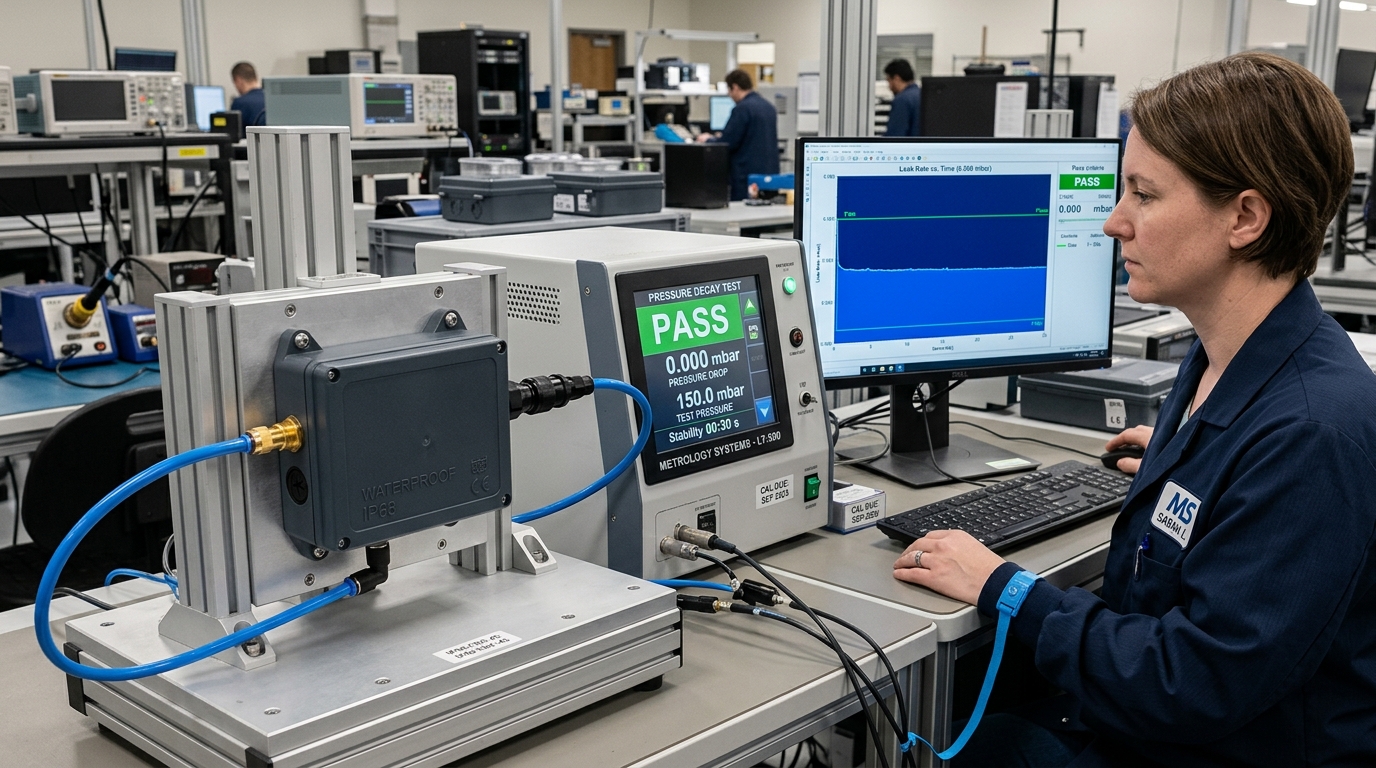
Submerging a live electronic prototype into water is the most intuitive test, but it is also the most destructive and least informative if a leak occurs. At AS Prototypes, our quality assurance lab implements a 3-tier leak verification protocol:
Stage 1: Automated Digital Pressure Decay Leak Testing
Before any contact with liquids, the prototype enclosure is mounted on a pneumatic test fixture and pressurized with clean, dry compressed air (typically 50 to 150 mbar for IP67/IP68 validation). The air supply is shut off, and a high-precision differential pressure sensor monitors pressure decay over a 30-second dwell cycle. A decay rate exceeding 0.001 mbar/sec instantly flags microscopic leakage, quantifying joint integrity down to leak channels smaller than 5 μm.
Stage 2: Vacuum Bubble Chamber Inspection (ASTM D3078)
If pressure decay reveals a leak, the enclosure is submerged in an illuminated clear acrylic vacuum chamber. The airspace above the liquid is evacuated, creating an internal-to-external pressure differential. The precise leak location is instantly pinpointed by a continuous stream of escaping micro-bubbles emerging from the failed joint, parting line, or fastener boss.
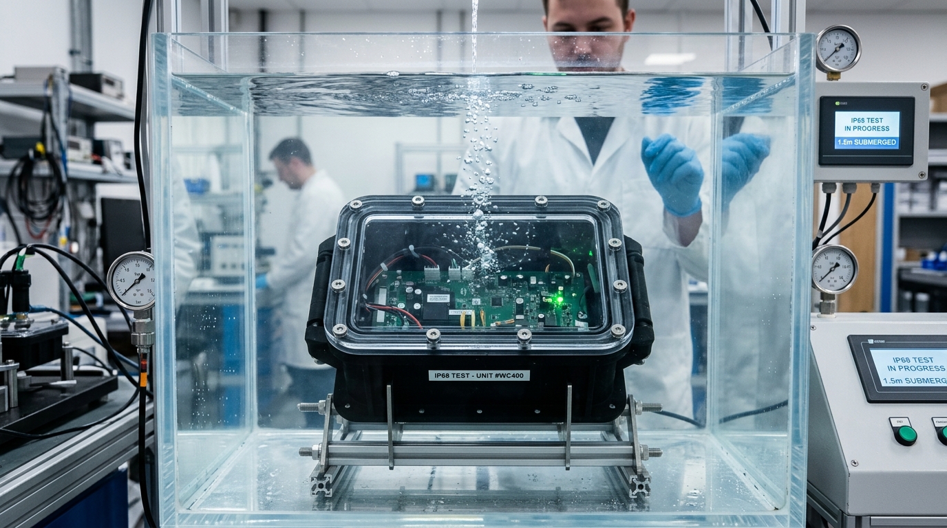
Stage 3: Submersion Verification (IPX7 / IPX8)
Once dry leak metrology passes, enclosures equipped with moisture indicator paper or real-time relative humidity telemetry sensors undergo immersion testing in our calibrated water column tank to validate and document compliance with IEC 60529 standards.
DFM Guidelines for Engineering Waterproof Plastic Enclosures
- Incorporate Internal Corner Radii: Avoid sharp 90° rectangular turns in the gasket channel. An O-ring bent around a sharp inside corner will bunch up and buckle; specify an inside corner radius of at least 1.5× to 2.0× the gasket cross-sectional diameter.
- Equip with Pressure Equalization Vents: In outdoor devices exposed to solar heat cycles, internal air expands rapidly, creating positive internal pressure. When the sun sets or cold rain strikes, internal pressure plummets, creating a partial vacuum that literally sucks water droplets past the seal. Incorporating an ePTFE hydrophobic/oleophobic membrane vent (e.g., Gore vent) equalizes atmospheric pressure while blocking liquid ingress.
- Keep Parting Lines Away from Sealing Lands: On molded or cast housings, ensure the mold parting line does not cross the flat sealing land of the gland. Even a 0.05 mm flash burr or parting mismatch across the sealing surface will compromise an IP68 boundary.
- Reinforce Flange Ribbing: Add structural gussets and ribs adjacent to screw bosses to distribute compressive load evenly across the entire gland span, eliminating local flange bowing.
For static face seals, aim for 20% to 30% cross-sectional compression. Exceeding 35% compression induces excessive tensile stress and premature elastomer creep, while under 15% risks capillary micro-leakage under water pressure.
Ambient temperature changes cause internal air to expand or contract. An ePTFE membrane vent equalizes internal and external pressure while blocking liquid water, preventing vacuum suction that draws water through joint seams.
Seal gland walls and floor should maintain a surface finish of Ra 0.8 µm or better. Tool chatter, burrs, or rough radial cutter marks along the sealing face create microscopic capillary leak paths across the gasket.
Engineer Your Waterproof Plastic Prototype with AS Prototypes
Navigating the complex mechanics of IP67 and IP68 ingress protection requires deep manufacturing know-how. At AS Prototypes, we combine high-precision 5-axis CNC machining, silicone vacuum casting, rapid tooling, and in-house digital pressure decay leak testing to turn your sealed enclosure designs into production-grade physical reality.
Our engineering team conducts comprehensive Design for Manufacturing (DFM) reviews on every project—evaluating gasket gland volume fills, compression ratios, parting lines, and clamp bolt distribution before cutting the first chip.
Upload 3D CAD Files for Instant Ingress Protection DFM Review →