Precision CNC machining is the premier manufacturing process for producing robust, functional, and dimensionally accurate prototype parts in real production metals and engineering plastics. However, hardware startups and engineering teams frequently face an uncomfortable reality: prototype CNC quotes can fluctuate wildly. Two parts with nearly identical physical outer bounding boxes can differ in machining cost by 300% to 500%.
Why does this happen? Unlike 3D printing where build cost is driven primarily by part volume and bounding envelope, CNC machining is a subtractive process governed by machine cycle time, cutting tool reach, setup changes, and workpiece rigidity. A minor, non-functional aesthetic choice on a 3D CAD model can force a machine shop to use micro-endmills at glacial feed rates, dramatically inflating spindle time.
At AS Prototypes, our engineering team reviews hundreds of customer CAD models every week. In this guide, we reveal the fundamental cost breakdown of precision CNC machining and provide seven actionable Design for Manufacturability (DFM) strategies to cut your CNC prototyping cost by up to 50% without compromising mechanical performance.
The Anatomy of CNC Machining Costs
To optimize costs, engineers must understand what a machine shop bills for:
- Machine Hourly Rate: Depending on the sophistication of the machine tool, rates range from $40–$60/hour for standard 3-axis vertical mills to $85–$130+/hour for simultaneous 5-axis machining centers and multi-spindle mill-turn machines.
- CAM Programming & Setup Time: Every job requires toolpath generation, G-code post-processing, fixture prep, datum zeroing, and touch-off probing. For a single prototype, setup often represents 50% or more of the invoice.
- Raw Material Mass vs. Finished Part Weight: Raw billet stock is purchased as a rectangular block. If your finished component is a thin, hollow skeletal bracket, up to 80% to 90% of that raw billet is converted into scrap chips that you still pay for.
- Specialized Tooling & Cycle Wear: Deep pockets requiring specialized long-reach carbide cutters, custom form tools, or micro-drills (< 1 mm) add direct tooling fees and risk tool breakage.
7 Proven DFM Rules to Slash CNC Prototyping Costs
1. Increase Internal Corner Radii
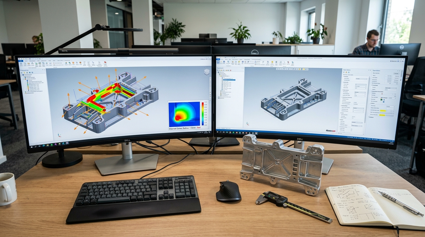
CNC milling cutters are cylindrical rods that naturally produce rounded internal corners. Designing sharp 90° internal vertical corners requires slow secondary Wire EDM cutting or broaching. Furthermore, if you specify an internal radius of 3.0 mm, a machinist must use a 6.0 mm cutter that engages 90° of material simultaneously at the corner, creating severe chatter. Best Practice: Make the internal corner radius slightly larger than standard tool radii (e.g., specify R3.2 mm or R3.5 mm instead of R3.0 mm). This allows the tool to transition smoothly through corners without decelerating.
2. Limit Pocket Depth-to-Width Ratios
As a cutting tool extends deeper into a cavity, its deflection increases by the cube of its length (Deflection ∝ L³). Machining deep, narrow pockets forces the machinist to drastically reduce spindle feed rates and take microscopic step-downs to prevent tool chatter and snapping. Best Practice: Keep cavity depths under 4 times the tool diameter (Depth ≤ 4×D). If deep pockets are unavoidable, incorporate stepped draft angles to allow larger, stiffer tool shanks.
3. Avoid Paper-Thin Walls
Thin walls vibrate under high-speed cutting forces, resulting in wavy chatter marks and dimensional warping. Achieving tight tolerances on thin walls requires machinists to perform multiple light, gentle passes, dramatically extending cycle time. Best Practice: Maintain a minimum wall thickness of 0.8 mm for aluminum and 1.5 mm for plastics (like ABS or POM). For tall structural ribs, maintain a height-to-thickness ratio under 10:1.
4. Rationalize Tolerances & Surface Finishes
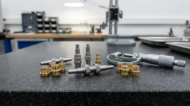
Over-tolerancing is the single most common cost multiplier in prototype drawings. Placing a blanket title-block tolerance of ±0.01 mm across an entire part forces the shop to slow down feed rates, continuously inspect non-critical faces, and potentially perform secondary grinding. Best Practice: Apply standard commercial tolerances (ISO 2768-m, ±0.1 mm to ±0.2 mm) to general exterior clearance contours. Reserve ±0.01 mm exclusively for critical dowel pin holes, bearing press-fits, and O-ring sealing surfaces.
5. Minimize Fixture Setups via Multi-Axis Machining
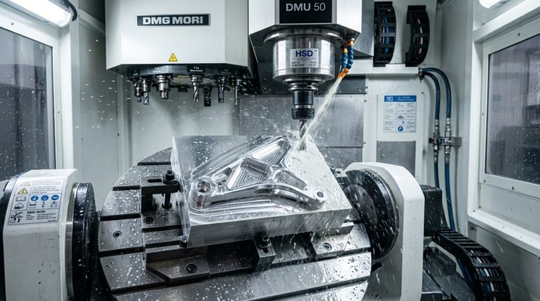
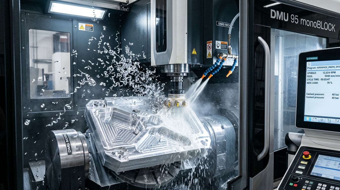
Every time a part must be unclamped, flipped, and re-aligned in a vise, the operator must re-probe datum coordinates, introducing labor cost and tolerance stacking errors. A part requiring 6 different orientations on a 3-axis mill involves substantial human intervention. Best Practice: Design features so that as many cuts as possible can be accessed from a single top-down orientation, or leverage 5-axis simultaneous CNC machining to access five faces in a single clamping setup.
6. Optimize Material Selection for Machinability
The cost of raw material is often dwarfed by how quickly it can be cut. Aluminum 6061-T6 has an exceptional machinability rating, allowing cutting speeds up to 10 times faster than austenitic stainless steel (such as 304 or 316) or titanium Ti-6Al-4V. Unless your prototype strictly demands extreme chemical immersion resistance or high-temperature biocompatibility, utilize aluminum 6061 or free-machining brass C360 for functional form and fit testing.
7. Order a Pilot Batch Instead of a Single Unit
Because CAM programming, machine setup, and first-piece probing represent fixed one-time engineering (NRE) costs, ordering a single prototype is the most expensive per-unit scenario:
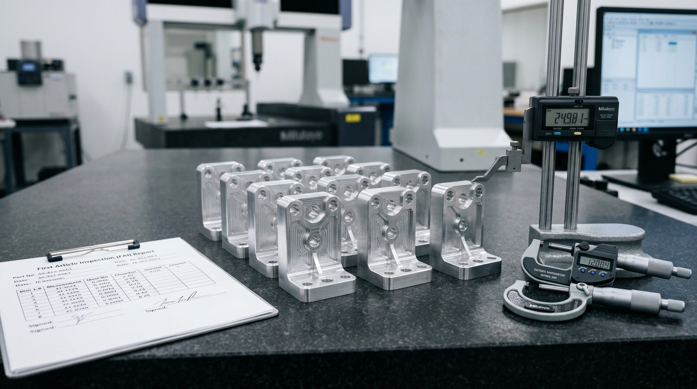
Ordering 5 to 10 prototype units allows the fixed setup cost to be amortized across the batch. While a single prototype might cost $250, ordering a batch of 5 units often costs only $400 total ($80 per unit)—a 68% reduction in unit cost while providing vital backup units for destructive mechanical testing, cosmetic reviews, and client presentations.
DFM Cost Impact Matrix for CNC Machined Prototypes
The table below illustrates how common design decisions directly impact machining cycle time and final quotation costs at AS Prototypes:
| Design Feature / Choice | Typical Added Cost (%) | Machining / Tooling Impact | Recommended DFM Best Practice |
|---|---|---|---|
| Sharp 90° Internal Vertical Corners | +25% – 50% | Requires secondary Wire EDM or micro-milling | Add radius ≥ 1/3 of pocket depth, or use dog-bone fillets |
| Deep Pockets (> 4× Tool Diameter) | +30% – 60% | Tool deflection, severe chatter, micro-step-downs | Limit depth to 3×–4× width, or add stepped side relief |
| Thin Structural Walls (< 0.8 mm) | +20% – 40% | Part harmonic vibration, risk of warping and scrap | Keep walls ≥ 1.0 mm (metal) or ≥ 1.5 mm (plastic) |
| Global Over-Tolerancing (±0.01 mm) | +35% – 70% | Forced slow feed rates, in-process CMM gauging | Use ISO 2768-m (±0.1 mm) for non-critical features |
| Multiple Fixturing Setups (5+ Sides) | +30% – 50% | Manual operator re-clamping and datum re-zeroing | Align cuts to 1–2 faces or utilize 5-axis indexing |
| Single Part vs. 5-Piece Pilot Batch | +60% per unit (Single) | Unamortized CAM programming and fixture prep | Order 3–10 units to cut average unit cost by 40%–65% |
Fast Turnaround & Precision CNC Machining at AS Prototypes
At AS Prototypes, our mission is to empower innovative hardware developers to iterate faster and build better products. With an advanced fleet of 3-axis, 4-axis, and simultaneous 5-axis CNC machining centers, automated touch-probes, and dedicated metrology labs, we deliver high-precision prototype parts with lead times as fast as 4 to 8 business days (Ex-Factory).
Every quote submitted to AS Prototypes includes complimentary DFM feedback from our senior engineering team, highlighting specific geometric optimizations to save you time and budget.
Looking to Cut Costs on Your Next CNC Prototyping Run?
Upload your 3D CAD files (STEP, IGES, SLDPRT) and 2D drawings today. Our engineering team will review your geometries, identify cost-reduction opportunities, and deliver an itemized quote within 24 hours.