

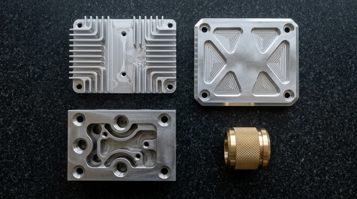
In hardware product development, robotics, aerospace, and medical device engineering, transitioning from a conceptual 3D CAD model to physical, functional metal and polymer components is the defining milestone of project feasibility. While additive manufacturing has unlocked geometric freedom for visual mockups, custom CNC machining remains the undisputed gold standard whenever mechanical assemblies demand isotropic material properties, structural rigidity, hermetic sealing, tight geometric tolerances (±0.010 mm / ±0.0004 in), and engineering-grade surface finishes.
However, for mechanical designers, hardware entrepreneurs, and procurement specialists, procuring custom CNC parts can feel like navigating an opaque minefield of machinability trade-offs, setup multiplication costs, and hidden tolerance pitfalls. Sourcing parts is not simply about uploading a STEP file and clicking a button; it requires an intimate understanding of how design choices dictate manufacturing kinematics, tooling accessibility, cycle times, and inspection overhead. This comprehensive engineering guide deconstructs the complete lifecycle of sourcing custom CNC parts—from DFM optimization and material selection to multi-axis machining, metrological verification, and post-finishing.
- Core Focus & DFM Scope: Actionable shop-floor engineering guidelines for custom CNC parts, covering material selection, geometric tolerancing, and defect prevention.
- Achievable Tolerance Envelope: General features hold ISO 2768-mK; critical bearing bores, dowel pins, and mating datums hold ±0.010 to ±0.020 mm (±0.0004″ to ±0.0008″), with Wire EDM/grinding to ±0.005 mm (±0.0002″).
- Machining & Surface Integrity: High-speed 3-axis and 4-axis VMCs (with simultaneous 5-axis for complex contours) delivering as-machined Ra 0.8 µm (32 µin) to Ra 0.4 µm (16 µin) per ASME B46.1.
- Metrology & Process Control: On-machine spindle probing paired with 20°C (68°F) climate-controlled Zeiss CMM coordinate verification and calibrated Go/No-Go plug/ring gauges.
- Ex-Factory Turnaround: 4 to 8 business days for as-machined rapid prototypes; 7 to 12 business days for anodized, plated, or multi-operation production runs (excluding 3–5 days air transit).
1. The Foundation: Transforming 3D CAD into Machinable Geometry (DFM)
The total manufacturing cost and production cycle time of custom CNC parts are fundamentally determined at the CAD drafting station. Design for Manufacturability (DFM) is the discipline of tailoring component geometry to leverage standard cutting tool kinematics, minimize machine setups, and eliminate unnecessary cost drivers.
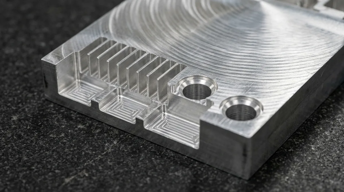
1. Cavity Depths and Internal Corner Radii
CNC end mills are cylindrical cutting tools rotating around a central spindle axis. Consequently, milling a square internal pocket or sharp 90° vertical inside corner is geometrically impossible without specialized secondary Wire EDM operations. To optimize toolpath efficiency:
- Inside Corner Radii: Always specify an internal corner radius slightly larger than the radius of standard end mills. For example, if designing for a 6 mm (1/4 in) end mill (radius 3 mm), specify an internal pocket corner radius of 3.2 mm to 3.5 mm. This allows the tool to interpolate smoothly through the corner without coming to an abrupt halt, preventing tool deflection, chatter marks, and spindle deceleration.
- Pocket Depth-to-Width Ratio: Keep cavity depths within 3× to 4× the cutting tool diameter. While reach extensions and long-flute end mills exist, tooling deflection increases cubically with tool overhang length (δ ∝ L3). Milling pockets deeper than 4× tool diameter mandates reduced feed rates, light radial stepovers, and custom long-neck tooling, radically escalating machining cycle times.
2. Wall Thickness Boundaries
As thin walls are machined, cutting forces and high-pressure coolant jets induce cyclical vibrations, leading to dimensional tapering and poor surface finish. As an empirical engineering benchmark:
- Aluminum & Structural Metals: Maintain a minimum wall thickness of 0.8 mm (0.032 in) for low-aspect structural webs, and at least 1.5 mm for tall walls (> 25 mm).
- Engineering Polymers (Delrin, Nylon, PEEK): Maintain a minimum wall thickness of 1.5 mm (0.060 in). Plastics exhibit lower modulus of elasticity and high thermal expansion coefficients; thin walls will elastically deflect away from the cutting edge and warp upon release from clamping fixtures.
3. Standardized Thread Depths & Tapped Holes
A frequent CAD oversight is designing tapped blind holes with full threads extending to the absolute bottom of the hole. Standard cutting taps and roll form taps require a conical lead-in chamfer of 1 to 3 threads:
- Rule of Thumb: Design blind hole pilot drill depths to exceed the tapped thread length by at least 3× the thread pitch.
- Engagement Depth: Maximum holding strength in ductile metals (like 6061-T6 aluminum) is fully realized within 1.5× to 2× the nominal screw diameter. Threading a blind hole deeper than 2.5× diameter yields zero additional mechanical pullout strength while drastically multiplying tap breakage risk.
2. Material Selection: Aligning Performance, Weight & Machinability
Selecting the optimal raw material requires balancing functional requirements—yield strength, fatigue life, operating temperature, electrical conductivity, and corrosion resistance—against raw stock material costs and machinability index ratings.
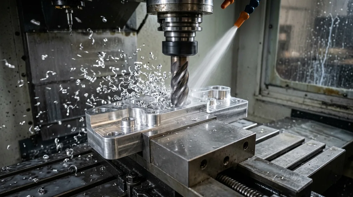
1. Aluminum Alloys: The Benchmark for Precision Prototyping
- Aluminum 6061-T6: The ubiquitous workhorse of precision machining. Offers excellent machinability, high strength-to-weight ratio, structural weldability, and superior response to Type II decorative anodizing and Type III hardcoat. Ideal for electronics enclosures, mounting brackets, robotic linkages, and automation fixtures.
- Aluminum 7075-T651: Zinc-alloyed aerospace aluminum delivering exceptional tensile strength (~570 MPa) comparable to low-carbon structural steels, but at one-third the density. Perfect for high-stress aerospace bulkheads, drone motor mounts, and high-load mechanical gears. Note: Less corrosion resistant than 6061 and produces a slightly darker, muted finish when anodized.
- Aluminum 2024-T3 / MIC-6 Tooling Plate: 2024 provides outstanding fatigue resistance for cyclic aerospace airframes. MIC-6 cast plate provides near-zero internal residual stresses, making it the premier choice for large vacuum platens and optical breadboards requiring extreme flatness (±0.05 mm) after heavy pocket milling.
2. Stainless Steels & High-Strength Tool Steels
- Austenitic Stainless (304 & 316L): 304 provides baseline food-grade corrosion resistance, while 316L contains 2~3% Molybdenum, delivering superior resistance to chloride pitting in marine and medical environments. Both alloys work-harden rapidly during cutting, demanding rigid setups, positive rake carbide inserts, and constant chip load feeds.
- Martensitic & Precipitation-Hardened Stainless (17-4 PH / 420): 17-4 PH can be machined in Condition A (annealed) and subsequently heat-treated (H900 to H1150) to Rockwell C 28~44 with minimal dimensional distortion. Crucial for surgical instruments, drive shafts, and high-pressure fluid manifolds.
3. Engineering Polymers & Turned Micro-Components
- POM (Acetal / Delrin): Extraordinary dimensional stability, low friction coefficient, very low moisture absorption, and clean chip formation without burring. Standard for precision gears, bearing bushings, and fluid valves.
- PEEK (Polyetheretherketone): Extreme chemical resistance, continuous service temperature up to 250°C, and biocompatibility. Frequently replaces titanium in aerospace electrical connectors, downhole oil/gas sensors, and medical implants.
- Precision Turned Brass (C3604): Free-cutting brass delivers outstanding machinability rating (100% baseline), low tool wear, and natural lubricity for precision bushings, threaded inserts, and fluid fittings processed on automated Swiss-type lathes.
3. Kinematics & Machine Setup: 3-Axis, 4-Axis vs. 5-Axis Machining
The number of machining setups required to produce a part is the single largest driver of labor cost and geometric stack-up error. Whenever an operator unclamps a part, repositions it in a second vise, and resets the work coordinate system (WCS G54 → G55), minor positional errors (±0.010 to ±0.020 mm) are unavoidably introduced.
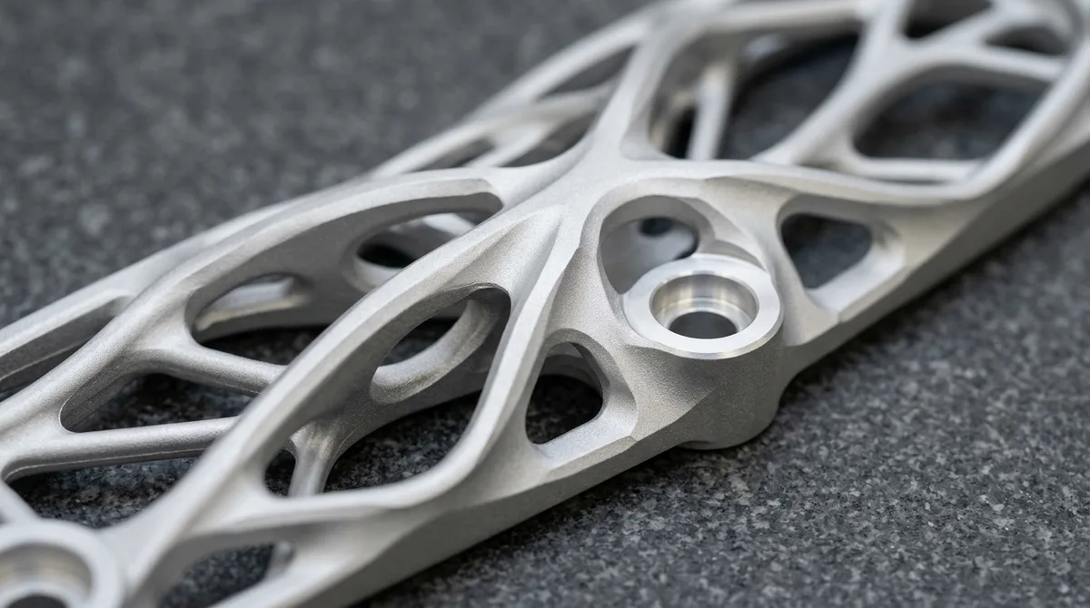
- 3-Axis Vertical Machining Centers (VMC): Cutting tool moves along X, Y, and Z axes. The shop-floor workhorse handling 75% to 85% of precision machining volume. Highly cost-effective for prismatic geometries, 2.5D planar plates, and structural enclosures. Parts with features on multiple orthogonal faces require 2 to 6 manual setups, increasing turnaround time and fixture tooling costs. Learn more about our CNC milling services.
- 4-Axis Machining (Rotary A/B Axis): Incorporates a rotary indexer or continuous trunnion table. Enables continuous rotary milling of cylindrical geometries, helical oil grooves, and multi-sided machining in a single clamping setup. Complementary to high-precision CNC turning services.
- Simultaneous 5-Axis Machining (Trunnion / Swivel Head): The workpiece rotates simultaneously across A and C (or B and C) axes while cutting along X, Y, and Z. Dedicated to complex organic contours, impellers, and deep cavities:
- “Done-in-One” Clamping: Machining 5 faces of a complex part in a single clamping setup using zero-point pneumatic chucks eliminates datum transfer errors.
- Shorter, Stiffer Tooling: Tilting the cutting tool or workpiece allows short, rigid stub end mills to access deep undercuts and contoured geometries without toolholder collisions, yielding mirror-like surface finishes and micron-level repeatability. Explore our advanced 5-axis machining capabilities.
4. Quality Assurance, Metrology & First Article Inspection (FAI)
A precision CNC part is only as good as the metrology data and inspection report validating its compliance. Professional machine shops operate under strict quality management systems (rigorous quality management, aerospace-grade quality protocols, medical-grade quality protocols) backed by calibrated metrological hardware:
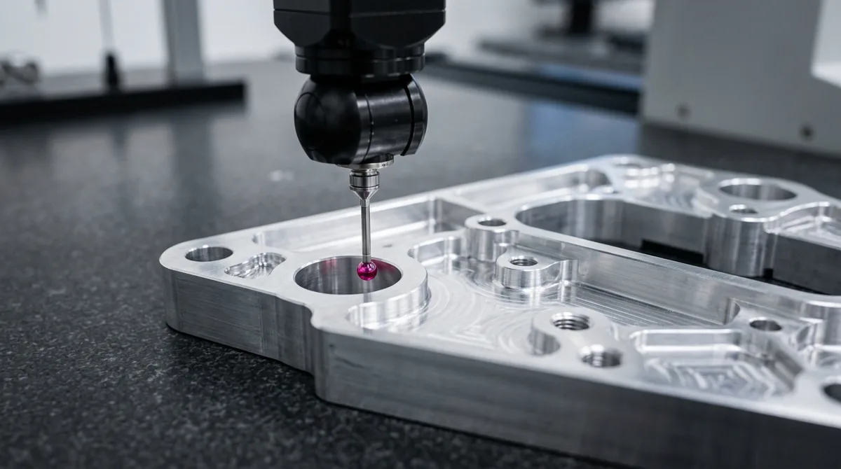
1. Coordinate Measuring Machines (CMM)
Modern CNC machine shops utilize high-precision bridge or portal CMMs (e.g., Zeiss) housed within temperature- and humidity-controlled cleanrooms (20°C ± 0.5°C). Equipped with automated ruby-tipped scanning touch probes, CMMs map complex 3D spatial points, validating true position, profile of a surface, concentricity, and perpendicularity datums down to tight-tolerance precision (±0.005 mm measurement uncertainty).
2. Optical Video Measuring Systems (VMM) & Air Bore Micrometers
Non-contact video measuring machines with telecentric optics inspect micro-features, delicate polymer chamfers, and internal thread pitches without physical probe deflection. High-precision bearing bores (tolerance classes H7/g6) are verified using calibrated digital three-point internal micrometers or pneumatic air bore gauges.
3. First Article Inspection (FAI) Reporting
For aerospace and medical prototypes, formal First Article Inspection (FAI) documentation is provided comprising:
- Form 1: Part Number Accountability and BOM tracking.
- Form 2: Product Process and Material/Finish documentation (traceable Mill Test Reports and chemical plating batch documentation).
- Form 3: Characteristic Accountability (every individual dimension, GD&T callout, and drawing note ballooned and recorded with nominal, upper/lower tolerance, measured value, and pass/fail status).
5. Surface Finishing: Enhancing Aesthetics, Wear & Corrosion Resistance
Freshly milled metal parts exhibit visible tool marks and cutter scallops. Post-machining surface treatments provide required environmental durability and cosmetic appeal:
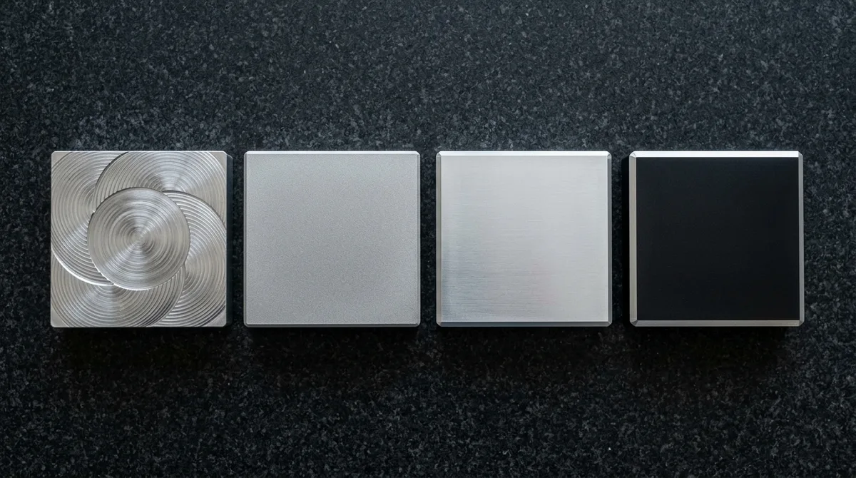
- As-Machined (Standard Ra 1.6 to 3.2 μm): Natural finish displaying directional tool marks. Best suited for functional internal prototypes, structural weldments, or budget-critical engineering fit checks.
- Abrasive Bead Blasting (Ra 0.8 to 1.6 μm): Compressed air propels fine spherical glass beads (#100~#150 mesh) inside automated cabinets. Blasting removes microscopic burrs, blends minor CNC tool stepovers, and imparts an elegant, non-directional satin matte texture.
- Type II Sulfuric Anodizing (MIL-A-8625 Type II): Electrochemical oxidation forming an aluminum oxide layer (10~15 μm) that can be dyed in vibrant cosmetic colors (Black, Clear, Red, Blue, Gold) while resisting atmospheric oxidation.
- Type III Hardcoat Anodizing (MIL-A-8625 Type III Class 1/2): Low-temperature acid bath producing a dense, wear-resistant ceramic layer (25~50 μm) reaching 400 to 550 HV0.05 microhardness. Indispensable for military components, hydraulic piston housings, and sliding wear guides.
- Electroless Nickel Plating (ASTM B733): Autocatalytic chemical deposition providing 100% uniform nickel-phosphorus coating across complex internal channels, blind holes, and threads without edge buildup. Outstanding for corrosion and wear resistance on steel, brass, and aluminum.
- Passivation & Electropolishing: Acid chemical passivation (ASTM A967) strips free iron from stainless steel surfaces, creating a protective chromium oxide barrier. Electropolishing dissolves microscopic surface peaks, achieving a mirror-like Ra < 0.2 μm finish for sanitary semiconductor and pharmaceutical fluid fittings.
6. Engineering Parameter Matrix: Custom CNC Machining Capabilities
The following engineering matrix summarizes standard and advanced manufacturing specifications for custom CNC parts at AS Prototypes:
| Manufacturing Parameter | Standard Production Specification | High-Precision Aerospace / Medical Tier | Critical Design Guidelines |
|---|---|---|---|
| Linear Dimensional Tolerance | ISO 2768-mK (±0.1 mm to ±0.3 mm for features up to 120 mm) | ±0.010 mm to ±0.020 mm (CNC Machining); down to ±0.005 mm (Precision Grinding / Wire EDM) | Tight tolerances should be restricted only to critical bearing fits, datum pins, and sealing lands. |
| Geometric Tolerancing (GD&T) | Perpendicularity / Flatness: 0.05 mm | True Position: ∅0.015 mm; Profile: 0.020 mm | Establish explicit Primary, Secondary, and Tertiary datums (A, B, C) referenced on functional mating planes. |
| Maximum Machining Envelope | 1200 × 800 × 600 mm (3-Axis VMC) | 650 × 650 × 500 mm (Simultaneous 5-Axis) | Consider tool reach limitations and fixture clearance envelopes when scaling large enclosures. |
| Surface Roughness (Ra) | Ra 1.6 μm to 3.2 μm (As-Milled) | Ra 0.2 μm to 0.4 μm (Diamond Milling / Lapping) | Specify Ra 0.8 μm for dynamic fluid seals; Ra 1.6 μm is optimal for standard bead blasted & anodized surfaces. |
| Minimum Wall Thickness | Metals: 0.8 mm; Plastics: 1.5 mm | Metals: 0.5 mm (Specialized High-Speed Trochoidal) | Avoid tall unsupported thin ribs; incorporate structural gussets to suppress harmonic chatter. |
| Quality Verification Protocols | Calipers, Micrometers, Height Gauge, Pin Gauges | Zeiss CNC CMM Scanning, Optical VMM, FAI Inspection Reports | Provide ballooned 2D PDF drawing alongside 3D STEP solid models to ensure 100% characteristic traceability. |
7. Step-by-Step Procurement: How to Source Custom CNC Parts Seamlessly
Working with an offshore precision manufacturing partner should accelerate your engineering roadmap, not introduce administrative friction. Following this proven procurement protocol ensures predictable results on time and within budget:
- Prepare Your Engineering Package:
- 3D CAD Model: Export native solid models in neutral STEP (.stp) or Parasolid (.x_t) format. Avoid tessellated mesh files (STL/OBJ), which convert smooth continuous curves into thousands of planar facets.
- 2D Engineering Drawing (PDF): Include critical tolerances, GD&T datum frames, tapped hole callouts, surface roughness symbols, and finish specifications. If tolerances are not called out on the 2D print, standard ISO 2768-mK tolerances will govern the 3D model.
- Request an Engineering DFM & Quotation: Upload CAD files through our secure portal. Our engineering team conducts a thorough geometry review for tool access, deep internal radii, and potential material stress warping, providing actionable DFM feedback within 24 hours.
- Inbound Material Verification & CAM Programming: Upon order release, raw material mill certificates are verified, and multi-axis G-code toolpaths are simulated in advanced CAM software before releasing to shop floor CNC controllers.
- In-Process Probing & First Article Inspection: The first machined article is verified on calibrated CMMs and signed off before releasing batch volume.
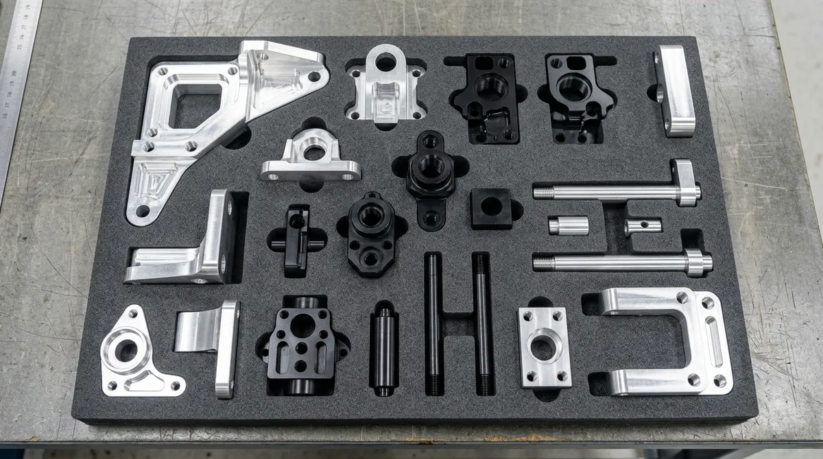
- Surface Treatment & Protective Packaging: Parts undergo precision bead blasting, anodizing, plating, or laser marking, followed by custom multi-layer foam packing to guarantee zero transit damage during international air freight (3 to 5 business days transit).
For aluminum alloys (6061, 7075), effective thread engagement beyond 1.5 to 2.0 times the nominal diameter provides virtually no additional pull-out strength. Excessively deep tapped holes dramatically increase tap breakage risk and tooling costs.
5-axis simultaneous machining enables ‘Done-in-One’ processing. By finishing 5 faces in a single setup, it eliminates complex modular fixtures, reduces manual handling, and eliminates datum transfer stackup errors between operations.
Supply native STEP (AP214/AP242) or Parasolid (.x_t) files for 3D prismatic geometry, paired with a detailed 2D vector PDF specifying GD&T tolerances, thread pitch classes, surface roughness (Ra), and post-treatment callouts.
Source Precision Custom CNC Parts with AS Prototypes
Whether you need rapid functional prototypes for design verification or precision production components, AS Prototypes delivers end-to-end CNC manufacturing under one roof. Our precision facility operates high-speed 3, 4, and 5-axis CNC machining centers, automated Swiss lathes, and temperature-controlled Zeiss CMM metrology labs.
Upload your 3D CAD files today for a confidential Design for Manufacturability review, custom itemized quotation within 24 hours, and reliable turnaround backed by comprehensive First Article Inspection (FAI) reports.







