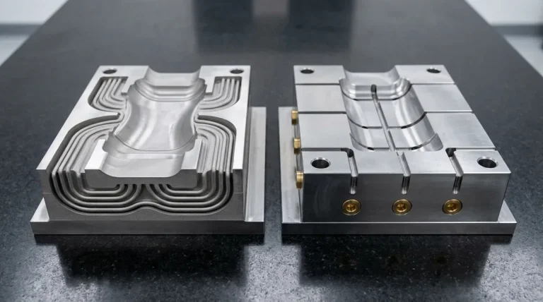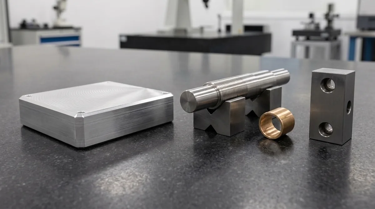
For hardware engineering teams, mechanical designers, and technical procurement specialists, choosing where to build precision parts has fundamentally shifted. The rapid proliferation of on-demand manufacturing platforms has introduced instant algorithmic quotes, automated 3D model parsing, and distributed subcontractor networks. Concurrently, partnering directly with a dedicated precision CNC machine shop remains the gold standard for tight-tolerance aerospace, medical, automotive, and industrial components.
While digital aggregator platforms market friction-free convenience through an automated browser upload, physical chip-making remains strictly governed by thermodynamics, cutting mechanics, workpiece deflection, and geometric dimensioning. When high-value programs move from initial conceptual ideation into functional validation and series production, the structural divergence between an algorithmic aggregator network and a direct manufacturing facility becomes critical to project timelines, budget predictability, and part performance.
At AS Prototypes, our precision manufacturing facility combines rapid engineering response with direct shop-floor execution. By working directly with our in-house CAM programmers, tooling specialists, and metrology personnel, engineering teams eliminate intermediary markups, resolve complex design-for-manufacturability (DFM) challenges before chips fly, and maintain complete chain of custody over flight-critical hardware.
Executive Summary & Engineering Takeaways (BLUF)
- Operational Model Divergence: Digital on-demand platforms operate as algorithmic aggregator marketplaces, distributing CAD files to anonymous bidding sub-tiers with an embedded intermediary margin on every order. Direct machine shops manufacture 100% of parts in-house with dedicated equipment and direct engineering accountability.
- DFM & Cutting Physics: Quoting algorithms evaluate bounding-box volumes and surface meshes but fail to predict cutting tool deflection (δ = F·L³ / 3EI), thin-wall residual stress distortion, or blind-hole tap clearing. Direct machine shop engineers evaluate physical toolpaths, custom soft jaws, and chip dynamics within 24 hours of CAD review.
- GD&T & True Positional Tolerances: Aggregator platforms enforce broad catalogue default tolerances (ISO 2768-mK or ±0.100 mm) and frequently miss 2D drawing callouts. Direct machine shops routinely execute critical bearing fits, dowel positions, and bores to ±0.010 mm to ±0.020 mm, with slow wire EDM and jig grinding reaching ±0.005 mm verified on calibrated Zeiss bridge CMMs.
- Production Capacity & Machine Realities: Direct machine shops deploy high-speed 3-axis and 4-axis vertical machining centers (VMCs) as core workhorses to produce 75% to 85%+ of prismatic parts cost-effectively, deploying simultaneous 5-axis centers strategically for continuous complex contours, impellers, and fluid manifolds.
- Total Cost of Ownership (TCO): Platform unit economics flatten rapidly beyond 10 pieces due to embedded intermediary margins. Direct machine shops leverage tooling amortization, multi-part vise setups, and high-speed machining to deliver substantial volume discounts across pilot runs (10 to 1,000+ units).
Engineering Review Directory
- 1. Structural Architecture: Algorithmic Aggregators vs. In-House Machine Shop
- 2. Automated Quoting Algorithms vs. Shop-Floor Cutting Mechanics
- 3. Custom Tolerancing, GD&T Standards, and Zeiss CMM Verification
- 4. Total Cost of Ownership: Intermediary Markups vs. Direct Economies
- 5. Machine Tool Realities: Shop-Floor Workhorses vs. 5-Axis Strategy
- 6. Quality Repeatability, Material Traceability, and IP Chain of Custody
- 7. Engineering Sourcing Playbook: Strategic Decision Framework
- 8. Frequently Asked Technical Questions (FAQ)
1. Structural Architecture: Algorithmic Aggregators vs. In-House Machine Shop
To accurately evaluate on-demand manufacturing platforms against direct machine shops, engineering procurement teams must look past user interface graphics and trace how purchase orders, CAD geometry, and production liabilities move through each system. The fundamental difference lies in physical machine ownership, technical communication lines, and operational incentives.
Digital on-demand platforms operate fundamentally as digital manufacturing aggregators or marketplace networks. Their core business model centers on digital front-end customer acquisition and algorithmic order routing. When a customer uploads a 3D CAD model (STEP, IGES, or Parasolid), the platform’s proprietary geometry engine processes the file, matches the bounding box and estimated machine time to a dynamic pricing matrix, and generates an automated quote in seconds.
Once the purchase order is funded, the digital platform acts as a clearinghouse. It broadcasts the digital package into a private marketplace of external subcontractor machine shops. These sub-tier suppliers bid on the job based on remaining machine capacity or receive automatic assignments dictated by platform margin targets. The physical manufacturing takes place at an anonymous supplier facility whose identity, machine vintage, tooling inventory, and internal inspection protocols remain concealed from the purchasing engineer.
This distributed aggregator model introduces severe organizational friction known as the engineering telephone game. When a subcontractor machinist encounters an ambiguous drawing datum, a tight internal corner, or an unmachinable undercut, they cannot directly phone the design engineer. Instead, technical RFIs (requests for information) pass from the machinist to the subcontractor’s manager, then to the platform’s customer support tier, then to the buyer’s procurement desk, and finally to the mechanical design engineer. Answers trace the same convoluted reverse path, introducing days of latency and frequent misinterpretations.
In sharp contrast, a direct precision machine shop operates on single-source, end-to-end engineering integration. At AS Prototypes, the team that reviews your 3D CAD model and 2D engineering drawings is the same in-house engineering group responsible for CAM programming, setup fixture fabrication, CNC spindle operation, and final metrology verification.
When you submit a project to our direct machine shop, our senior process engineers examine the STEP model alongside the GD&T drawing within 24 hours. If an internal corner radius causes excessive tool overhang or a tapped blind hole lacks thread relief, our engineers provide direct, redlined DFM feedback complete with suggested geometric modifications. The customer communicates one-on-one with experienced machinists who understand cutter dynamics, machine clearances, and metal behavior on the shop floor.
2. Automated Quoting Algorithms vs. Shop-Floor Cutting Mechanics
Instant quoting engines deployed by on-demand platforms rely heavily on geometric heuristic algorithms and boundary-representation (B-rep) analysis. These software tools excel at calculating cubic material removal volume, bounding box envelopes, nominal hole counts, and estimated surface areas. However, physical chip removal does not take place inside an algorithmic cloud server; it occurs under intense mechanical cutting forces, thermal expansion gradients, and dynamic vibration harmonics.
Automated quoting software fundamentally lacks the capability to evaluate complex cutting physics. Consider the mechanics of end mill deflection during internal pocket milling. The static deflection δ of a solid carbide end mill acting as a cantilever beam is governed by Euler-Bernoulli beam theory:
δ = Fc · L³ / (3 · E · I)
In this equation, Fc represents the tangential cutting force, L is the tool overhang length from the toolholder collet, E is the Young’s modulus of the cutting tool substrate (approximately 550 to 650 GPa for ultra-fine micrograin tungsten carbide), and I is the area moment of inertia of the tool cross-section (I = π · d⁴ / 64 for a solid cylindrical shank of diameter d). Because tool deflection scales with the third power of length (L³) and inversely with the fourth power of diameter (d⁴), doubling the tool overhang length L at constant diameter increases deflection by a factor of eight.
When a designer uploads an electronic housing featuring sharp internal corners with an L/D ratio exceeding 4:1, an automated platform bot merely flags a generic tool accessibility warning or applies an automated cost surcharge. The platform algorithm cannot determine whether the cutting tool will experience regenerative chatter, excessive surface waviness, or outright fracture during roughing passes.
On our shop floor, our manufacturing engineers evaluate cutter engagement angles and chip thinning dynamics directly. We identify deep pocket corners where a cutting tool encounters a 90-degree corner transition. At the instant of cornering, tool engagement expands from an optimal 15% radial immersion (ae) to a catastrophic 75% or 100% full-slotting condition, causing instantaneous cutting force spikes and chatter marks. Our engineers recommend increasing internal corner radii by at least 15% beyond the nominal cutter radius (Rcorner ≥ 1.15 · Rtool), allowing the CNC toolpath to roll smoothly around the radius without sudden acceleration drops or cutter deflection.
To eliminate tool deflection and optimize chip evacuation during pocketing, our CNC programmers configure continuous trochoidal and dynamic clearing toolpaths on high-speed vertical machining centers. By maintaining a constant radial engagement angle, cutting forces remain balanced across the toolholder assembly, delivering clean side-wall finishes and eliminating dimensional taper across deep cavity walls.
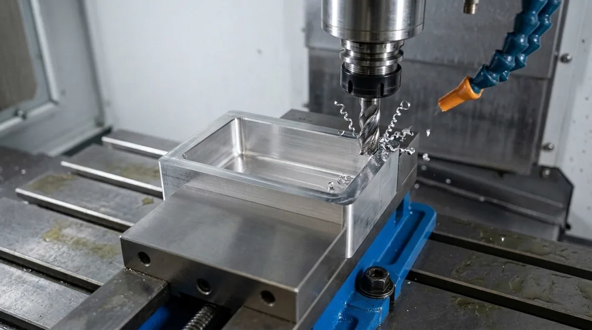
Another classic blind spot of platform quoting engines is residual stress release in structural billet materials. When machining asymmetrical structural components from cold-drawn or extruded aluminum bars (such as 6061-T6 or 7075-T651), the removal of outer material layers unbalances internal tensile and compressive stress states. Without specialized manufacturing sequences, the workpiece warps into a noticeable curve—commonly termed the "banana effect" on the shop floor.
An automated quoting portal accepts the CAD model blindly, quoting the part as a simple 3-axis prismatic block. An anonymous subcontractor, pressured to meet tight turnaround and cut-rate billing rates, runs the part in a single aggressive clamping setup. When unclamped, the part springs out of spec by 0.30 mm to 0.80 mm. At AS Prototypes, our process engineers foresee internal stress distribution. For precision thin-wall chassis (wall thicknesses t < 1.2 mm), we execute multi-stage roughing passes, unclamp the workpiece to relieve internal metallurgical tension, flip the component to skim opposite reference faces, and perform light finish passes with sharp, balanced micro-grain end mills to guarantee sub-0.020 mm flatness across the entire envelope.
| Engineering Metric | Digital On-Demand Platforms (Aggregators) | Direct Precision Machine Shop (AS Prototypes) |
|---|---|---|
| Production Facility | Distributed anonymous subcontractor network; physical shop location unknown | 100% In-house precision CNC machining, turning, and EDM facility |
| DFM Analysis | Automated geometric B-rep mesh heuristics; zero physical cutting force analysis | Hands-on review by senior tooling and CAM engineers delivered within 24 hours |
| Pricing Structure | Dynamic platform markup layered on top of the subcontractor’s quoted rate | Direct factory-floor costing based strictly on raw material, machine hours, and setup |
| Engineering Communication | Layered customer service ticketing; no direct contact with CAM programmers | Direct one-on-one communication with assigned project engineers and machinists |
| Custom Tolerancing | Standardized catalogue defaults (ISO 2768-mK or ±0.100 mm); drawing mismatches common | Precision tolerances down to ±0.010 mm on CNC milling/turning; ±0.005 mm on wire EDM |
| Quality Verification | Variable subcontractor inspection; sporadic pass-through visual checks | In-house climate-controlled metrology lab with Zeiss CMM and full dimensional FAIR |
| Workholding & Fixtures | Subcontractors limited to generic 3-axis vise clamping to preserve margin | Custom aluminum soft jaws, modular zero-point subplates, and vacuum fixtures |
| IP Protection | CAD geometry uploaded to external cloud and broadcast to broad bidding networks | Point-to-point NDA; CAD assets confined strictly to internal secured workstations |
3. Custom Tolerancing, GD&T Standards, and Zeiss CMM Verification
One of the most persistent failure points encountered by hardware teams using digital on-demand platforms is the "tolerance asterisk." When configuring an instant quote, automated platforms prominently advertise fast lead times, but the fine print binds the customer to broad general commercial tolerances. Most platforms default to ISO 2768-mK (medium linear and general geometric tolerance) or a flat ±0.100 mm to ±0.200 mm envelope.
In real-world electro-mechanical, aerospace, and medical assemblies, parts rarely feature uniform tolerance demands. A precision optomechanical lens barrel or gearbox chassis might possess general exterior dimensions that tolerate ±0.150 mm, but require specific cylindrical bearing journals held to an ISO H7 fit (for example +0.015 / 0 mm on a Ø8 mm bore), dowel pin press-fits held to ISO m6 (for example +0.012 / +0.004 mm on a Ø5 mm pin), and sealing faces requiring flatness within 0.012 mm relative to primary Datum A.
When an engineer attaches a 2D PDF drawing containing ASME Y14.5-2018 GD&T feature control frames to an automated platform order, the disconnect between digital interface and physical shop floor becomes apparent. Platform algorithms are designed to parse 3D solid geometry; they cannot reliably optical-character-read (OCR) complex 2D tolerance symbols, surface finish callouts (ASME B46.1 / ISO 4287 Ra), or composite position tolerances. The 2D PDF is simply attached as a secondary download file for the subcontractor.
If the winning subcontractor operates an older machine with mechanical backlash in the ballscrews or lacks in-house high-accuracy metrology equipment, the critical GD&T requirements are frequently compromised. Parts arrive with general dimensions matching the CAD model, but bearing bores show taper, and cross-hole concentricity fails during downstream cleanroom assembly.
Precision workholding and dedicated fixture engineering represent the cornerstone of tight-tolerance execution. To machine multi-sided complex geometries without losing relational datum accuracy, parts must be clamped rigidly in customized fixtures that withstand aggressive cutting loads without inducing elastic deformation.
At AS Prototypes, 2D engineering drawings with GD&T feature control frames are treated as binding technical contracts. When our engineers review a print, we establish the physical machining process around the customer’s specified datum reference frames (DRFs). If Datum A is the primary mounting plane, we skim that face first with an indexable face mill to establish a sub-0.008 mm planar reference, ensuring all subsequent perpendicularity, parallelism, and true position callouts remain mechanically anchored to that datum.
Our in-house manufacturing capabilities bridge the gap between general CNC milling and ultra-precision toolmaking tolerances:
- Standard CNC Milling & Turning: Standard general tolerances adhere to ISO 2768-mK. Precision bearing journals, dowel centerlines, and critical features are routinely held to ±0.010 mm to ±0.020 mm on high-speed CNC machining centers and CNC turning lathes with live tooling.
- Wire EDM & Micro-Machining: For deep, narrow slots, square internal corners (zero radius), and hardened steel components, our slow wire electrical discharge machining (EDM) cells achieve precision down to ±0.005 mm with mirror surface finishes down to Ra 0.4 μm.
- Cylindrical & Surface Grinding: Shafts, ground pins, and precision slide plates receive secondary surface grinding to hit sub-0.005 mm diametrical tolerances and Ra 0.2 μm finishes.
Metrology verification provides the essential link between drawing specifications and delivered physical parts. Resting flat on Grade 00 laboratory granite surface plates, every critical prototype and production run is verified using calibrated mechanical micrometers, digital height gauges, air bore gauges, and our high-accuracy bridge-type Zeiss Coordinate Measuring Machine (CMM).
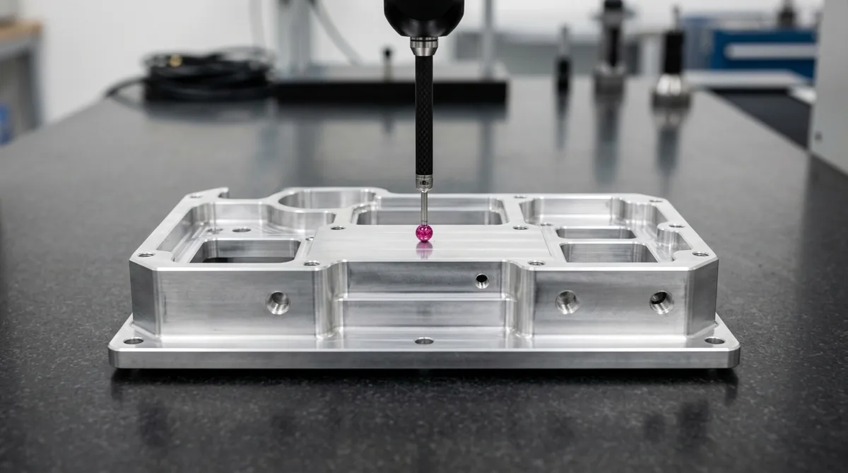
By executing multi-point touch-probe routines in our climate-controlled inspection lab (maintained at a stable 20°C ± 0.5°C to prevent thermal expansion measurement skew), we capture true position, profile of a surface, circular runout, and concentricity across complex 3D features. Customers receive full First Article Inspection Reports (FAIR) and dimensional inspection reports directly from our quality assurance team, providing indisputable physical validation before parts ship.
| Geometric Parameter | Digital Platform Default | Direct Machine Shop (AS Prototypes) | Verification Metrology |
|---|---|---|---|
| General Linear Dimensions | ISO 2768-mK (±0.100 mm to ±0.300 mm depending on length) | ISO 2768-mK standard; tighter linear callouts to ±0.025 mm | Calibrated digital vernier calipers, micrometers, and CMM |
| Bearing Bores & Dowel Fits | ±0.050 mm (requires custom quote surcharge; often missed) | ISO H7 / H8 bores and g6 / m6 shafts; critical features held to ±0.010 mm to ±0.020 mm | Three-point internal micrometers, plug go/no-go gauges, Zeiss CMM |
| True Position (GD&T) | Not verified unless premium inspection package is purchased | Held to Ø0.015 mm to Ø0.025 mm at MMC relative to Datums A-B-C | Zeiss bridge CMM continuous scanning touch-probe routines |
| Surface Roughness (Ra) | Standard as-machined: Ra 3.2 μm (125 μin); bead blast option | As-machined: Ra 1.6 μm (63 μin); fine passes to Ra 0.8 μm (32 μin) | Contact stylus surface profilometer (ISO 4287 / ASME B46.1) |
| Deep Narrow Slots / Micro-Features | Rejected by automated engine or quoted with massive penalty | Machined via slow wire EDM or high-speed micro-milling (±0.005 mm) | Optical measuring microscopes and laser non-contact scanning |
| Inspection Documentation | Basic certificate of conformance (CoC) or generic sample report | Comprehensive 100% FAIR, raw material MTRs, plating thickness reports | Serialized inspection data packet and calibrated tool calibration records |
4. Total Cost of Ownership: Intermediary Markups vs. Direct Economies
When procurement managers compare initial quotes between online on-demand platforms and direct precision machine shops, headline prices can create an illusion of parity. However, analyzing the Total Cost of Ownership (TCO) reveals critical economic divergence across different order sizes, setup complexities, and lifecycle stages.
The mathematical cost structure of sourcing through a digital manufacturing aggregator is governed by an unavoidable layer of intermediation:
Cplatform = ( Csubcontractor + Mplatform + Osoftware + Srepackaging ) × ( 1 + Prejection risk )
Here, Mplatform represents the platform markup layered above what the actual machine shop is paid for cutting the metal. Furthermore, Osoftware covers the platform’s substantial software engineering, cloud infrastructure, and customer acquisition overhead, while Srepackaging includes secondary transit legs where parts are shipped from the subcontractor to an aggregator sorting hub for white-label reboxing before final dispatch.
Crucially, Prejection risk captures the hidden engineering cost of rejected parts, delayed assembly lines, and internal sorting labor when out-of-spec components slip through distributed networks. When a batch of 50 precision manifolds arrives with out-of-tolerance O-ring grooves from an anonymous subcontractor, the project experiences weeks of schedule slip while tickets are processed through platform customer support.
In contrast, the cost equation of a direct precision machine shop is lean, physical, and transparent:
Cdirect = Craw material + Cspindle time + Ctooling & fixturing + Cfinishing & metrology
Because there is no intermediary margin, every unit of cost translates directly into physical manufacturing value: traceable aerospace-grade billet alloys (such as verified 6061-T6, 7075-T651, 316L, 17-4PH, or Grade 5 titanium), premium micrograin carbide cutting tools with advanced PVD coatings, dedicated multi-part fixture machining, and meticulous Zeiss CMM inspection.
The economic divergence becomes pronounced as quantities scale from single prototypes to bridge production (10 to 1,000+ pieces). On-demand platforms excel at instant automated quoting for 1 to 3 pieces because their software removes upfront human sales friction. However, their unit cost curve flattens rapidly. Because the platform must still subcontract the work to a shop that needs to turn a profit while preserving the platform’s own margin, the platform cannot pass true volume economies to the customer.
A direct precision machine shop approaches volume manufacturing through advanced production engineering:
- Fixture Amortization & Multi-Part Clamping: For an order of 100 aluminum valve bodies, our CAM team designs a multi-station vise fixture or tombstone setup that holds 8 to 16 parts in a single machine envelope. Tool changes are executed across all 16 parts simultaneously, substantially cutting cycle time per part.
- High-Speed Machining (HSM) Optimization: Spindle feed rates and trochoidal step-overs are tuned specifically for the production batch, maximizing metal removal rates (MRR) without tool wear spikes.
- Raw Material Mill Bulk Sourcing: Direct machine shops purchase full-length extruded bars and billets directly from primary metal distributors with official mill test reports (MTRs), securing wholesale material pricing that is passed directly to the client.
Consequently, while a digital platform’s price per unit may drop only modestly between a 5-piece order and a 100-piece order, a direct precision manufacturer typically delivers steep volume reductions, making direct partnerships dramatically more cost-effective for pre-series and series production.
5. Machine Tool Realities: Shop-Floor Workhorses vs. 5-Axis Strategy
A common misconception fostered by digital manufacturing portals is the "5-axis everywhere" narrative. Online platforms frequently market 5-axis CNC machining as a catch-all marketing badge, leading engineers to believe that every complex part requires a continuous five-axis machining center to achieve precision.
On a real-world precision machine shop floor, practical engineering and cost control dictate an entirely different, disciplined reality. In our precision facility, high-speed 3-axis and 4-axis vertical machining centers (VMCs) serve as the foundational workhorses, executing between 75% and 85%+ of all milled components.
The engineering rationale is rooted in machine dynamics, spindle stiffness, and setup economics:
- Spindle Rigidity and Metal Removal Rates: Heavy 3-axis and 4-axis VMCs equipped with robust BT40 or CAT40 dual-contact taper spindles provide immense structural rigidity. For square prismatic parts, electronic chassis, structural mounting brackets, heatsinks, and baseplates, a rigid 3-axis setup allows for aggressive heavy-roughing chip loads that 5-axis trunnion tables cannot match without risk of table deflection and vibration harmonics.
- Rapid Workholding Flexibility: Using precision Kurt vises, ground modular subplates, and custom aluminum soft jaws, a 3-axis or 4-axis machine can be set up and running in a fraction of the time required for complex 5-axis kinematic alignment and collision simulation.
- Cost Efficiency: Machine hourly operating rates on standard high-precision 3-axis and 4-axis machining centers are substantially lower than continuous 5-axis simultaneous machines. Forcing a standard five-sided prismatic bracket onto a 5-axis machine introduces unnecessary programming complexity, higher hourly machine billing rates, and extended CAM simulation overhead without improving part accuracy.
On our precision machine shop floor, modular workholding fixtures and zero-point clamping subplates form the technological foundation of high-efficiency 3-axis and 4-axis vertical machining centers. By docking self-centering precision vises directly onto pre-aligned ground subplates with hardened pull studs, our machinists achieve sub-0.005 mm pallet repeatability, enabling rapid changeovers between multi-sided housing operations without losing relational datum accuracy.
When is simultaneous 5-axis CNC milling truly mandatory? At AS Prototypes, our continuous 5-axis machining centers are deployed strategically as specialized high-performance assets for geometries that cannot be produced via 3-axis or 3+2 positional indexing:
- Continuous Freeform 3D Contours: Closed or open impellers, turbocharger blisks, aerodynamic turbine blades, and marine propulsors requiring the cutting tool axis to dynamically tilt to prevent cutter shank interference with adjacent blade surfaces.
- Complex Fluid Manifolds & Deep Cavity Undercuts: Hydraulic valve blocks and aerospace fluid distribution blocks where angled cross-ports, compound helical fluid paths, and internal undercuts require real-time dynamic tool center point management (RTCP).
- Done-in-One Multi-Sided Precision: Complex aerospace structural components where machining 5 sides in a single continuous clamping eliminates accumulated datum transfer errors (ΔDatum = Σ εi), locking cross-hole true positions within Ø0.015 mm relative to the primary mounting face.
By maintaining a balanced shop floor featuring high-speed 3-axis and 4-axis workhorse machines alongside advanced 5-axis simultaneous machining centers, AS Prototypes gives hardware teams the optimal balance: maximum cost efficiency on standard geometries and uncompromised multi-axis capability when aerospace geometries demand it.
6. Quality Repeatability, Material Traceability, and IP Chain of Custody
Beyond initial piece-part pricing, hardware engineering teams must protect two critical corporate assets: production consistency across reorders and intellectual property (IP) security.
A severe structural vulnerability of the digital aggregator model is known in the hardware industry as "Vendor Roulette." When you order 10 prototypes from an on-demand platform in January, the job might be routed to Shop A in Ohio. Shop A uses an ultra-rigid Makino machining center, fresh carbide end mills, and careful coolant maintenance, delivering beautiful parts that pass inspection.
Three months later, when you place a repeat reorder for 50 pieces for your EVT (Engineering Validation Test) build, the platform’s bidding algorithm re-auctions the CAD model. The order is won by Shop B, an entirely different shop operating older equipment with high ballscrew backlash and worn tooling. Despite identical nominal CAD geometry, the second batch exhibits noticeable variations: different surface lay patterns, altered anodizing gloss levels, slight dimensional shifts in press-fit pin bores, and inconsistent deburring.
Because the buyer never knows who machined either batch, diagnosing the root cause of assembly failures becomes nearly impossible. The customer has no way to request "the same machine, same CAM programmer, and same tooling setup" that worked successfully the first time.
At AS Prototypes, repeatability is built into our digital-to-physical shop floor workflow. When a job is programmed in Mastercam or hyperMILL, the exact CAM toolpaths, cutting tool assemblies, fixturing coordinates (G54 work offsets), and in-process inspection routines are cataloged and archived in our secured internal manufacturing database. When you issue a reorder six months or two years later, the identical tooling sequence and setup parameters are deployed on the same class of machine tool. This ensures absolute dimensional, cosmetic, and functional repeatability across every single production run.
Material integrity and secondary finishing represent another domain where direct machine shops provide vital chain-of-custody guarantees:
- Mill Test Reports (MTR): Direct machine shops source raw materials directly from verified metallurgical stockists. Every batch of 6061-T6, 7075-T651, 304, 316L, and Ti-6Al-4V is accompanied by traceable mill test reports detailing exact chemical composition (spectrometer analysis) and physical mechanical properties (tensile strength, yield point, and elongation).
- Process Standards Compliance: Surface finishing is tightly controlled according to recognized international engineering process specifications:
- Anodizing: MIL-A-8625 Type II (sulfuric acid anodizing for clear and dyed decorative wear protection) and MIL-A-8625 Type III Class 1/2 (hardcoat anodizing for extreme wear and dielectric resistance).
- Chemical Conversion Coating: MIL-DTL-5541 Type II Class 1A and Class 3 (RoHS-compliant clear and yellow chromate/alodine for corrosion protection and electrical conductivity).
- Stainless Passivation: ASTM A967 (citric or nitric acid passivation to chemically strip tramp iron and enrich chromium oxide surface passivation).
- Corrosion Testing: ASTM B117 neutral salt spray test verification (24 to 240 hours) to prove environmental resistance.
Finally, intellectual property (IP) protection cannot be overstated. When a hardware company uploads bleeding-edge, unreleased patent-pending CAD files to an on-demand aggregator platform, that geometry is distributed across wide subcontractor networks for competitive bidding. Multiple external companies, estimators, and external servers gain access to your proprietary design files.
Working directly with AS Prototypes guarantees airtight confidentiality. We sign robust, mutual Non-Disclosure Agreements (NDAs) prior to file submission. Your CAD geometry, 2D drawings, and proprietary engineering notes remain strictly confined within our secure, encrypted local servers, accessible solely by the dedicated in-house engineers assigned to program and inspect your hardware.
7. Engineering Sourcing Playbook: Strategic Decision Framework
Neither sourcing model is universally superior across every single manufacturing scenario. Skilled hardware engineering leaders and procurement managers establish dynamic sourcing frameworks, deploying on-demand platforms where their algorithmic speed shines, while anchoring critical hardware programs with a direct precision manufacturing partner.
To help engineering teams navigate this choice, the following decision playbook synthesizes practical shop-floor criteria:
| Project Phase / Part Characteristics | Optimal Sourcing Partner | Key Technical Rationale | AS Prototypes Engineering Fit |
|---|---|---|---|
| Early Concept Proof-of-Concept (POC) 1–3 parts, simple 2.5D shapes, loose tolerances (±0.150 mm) | Digital On-Demand Platform or Direct Shop | Instant web quote convenience; non-critical assembly allows standard catalogue tolerances | Rapid prototype turnaround in 4 to 8 business days with full material integrity |
| Functional Engineering Validation (EVT/DVT) 5–50 parts, tight bearing bores, sealing faces, GD&T callouts | Direct Precision Machine Shop | Requires 24-hour DFM review, direct CAM interaction, custom soft jaws, and Zeiss CMM verification | Senior engineer review, custom tolerances down to ±0.010 mm, 100% First Article Inspection Report |
| Flight-Critical / Medical / Optomechanical Complex 5-axis contours, thin walls, Ra ≤ 0.8 μm, strict material traceability | Direct Precision Machine Shop | Subcontractor blind bidding creates unacceptable quality and structural failure risks | Simultaneous 5-axis CNC machining, spectrometer-verified raw stock, traceable MTR documentation |
| Pre-Series & Bridge Production 50–1,000+ units, repeat reorders, cost-sensitive scaling | Direct Precision Machine Shop | Platform margins erode volume economics; direct shop amortizes multi-part fixturing | High-speed 3/4-axis multi-clamping setups; series production delivered in 7 to 30 business days |
| Proprietary / Patent-Pending Technology Strict confidentiality, unreleased novel mechanical architectures | Direct Precision Machine Shop | Avoids broadcasting proprietary CAD files to external bidding portals and multiple databases | Direct bilateral NDA; secure in-house encrypted storage; zero outside distribution |
When selecting your manufacturing route, keep the core production timelines clearly separated between factory manufacturing and international transit:
- Engineering DFM Review & Quotation: Completed within 24 hours directly by our senior tooling engineering team upon receipt of 3D CAD (STEP/IGES) and 2D PDF prints.
- Rapid Prototyping (Standard Machined & Unfinished): Dispatched ex-factory in 4 to 8 business days, incorporating dedicated CNC setups and comprehensive First Article Inspection.
- Prototypes with Advanced Surface Finishing: Anodized (MIL-A-8625), passivated (ASTM A967), or custom-plated prototypes completed in 7 to 12 business days.
- Low-to-Mid Volume Batch Production (10 to 1,000+ parts): Executed in 7 to 30 business days utilizing optimized multi-part workholding and high-speed CNC production cells.
- Rapid Tooling & Bridge Injection Molding: Completed in 18 to 35 business days for T1 sampling and pilot production.
- International Air Logistics: Factory dispatch is paired with express air transit (typically 3 to 5 business days via DHL, FedEx, or UPS Worldwide Priority) with full customs documentation and tracking.
8. Frequently Asked Technical Questions (FAQ)
Digital on-demand platforms operate as intermediaries, layering their own margin on top of what they pay their subcontracted machine shops. While their automated software lowers customer acquisition friction for 1 to 3 prototype parts, their unit pricing flattens out on larger quantities. A direct precision machine shop eliminates the intermediary markup entirely, leveraging custom multi-station vise fixtures, high-speed machining toolpaths, and wholesale billet sourcing to provide steep volume economies of scale across 10 to 1,000+ units.
No. Automated quoting engines parse 3D solid geometry (B-rep meshes) to estimate bounding boxes, surface areas, and nominal material removal. They cannot reliably interpret complex 2D PDF drawings containing ASME Y14.5-2018 GD&T feature control frames, datum reference schemes, or microfinish specifications. In contrast, direct machine shops assign experienced process engineers to review 2D drawings within 24 hours, ensuring critical bearing fits (±0.010 mm), true position callouts, and flatness requirements are physically achievable and measured on a calibrated Zeiss CMM.
When working through a digital platform, communication is mediated through customer support personnel who rarely have hands-on CNC machining experience, creating an engineering telephone game. Working directly with a machine shop connects you one-on-one with the CAM programmer and tooling lead. If an internal corner radius requires modification to prevent tool chatter or a tapped hole lacks adequate drill depth, the issue is resolved directly with a redlined CAD proposal, eliminating days of delay and preventing out-of-spec deliveries.
Digital platforms re-auction work orders across their subcontractor networks based on real-time machine capacity and margin targets. When you place a repeat order months later, it is often assigned to a completely different workshop with different machine rigidity, different CAM strategies, different tooling brands, and varied deburring practices. Direct machine shops archive the exact CAM programs, fixture setups, G54 work offsets, and tooling data from your initial run, guaranteeing identical cosmetic, mechanical, and dimensional repeatability across every future production batch.
Standard general CNC milling and turning tolerances follow ISO 2768-mK. Critical features such as bearing journals, dowel pin bores, and precision slide surfaces are routinely held to ±0.010 mm to ±0.020 mm, with slow wire EDM achieving down to ±0.005 mm. Standard ex-factory turnaround is 4 to 8 business days for rapid prototypes, 7 to 12 business days for surface-finished parts, and 7 to 30 business days for batch production (10 to 1,000+ units), with 24-hour response on engineering DFM reviews.
Accelerate Your Hardware with Direct Factory Engineering
Eliminate intermediary markups, miscommunicated tolerances, and subcontractor inconsistency. Upload your 3D CAD models (STEP/IGES) and 2D engineering drawings directly to AS Prototypes. Our senior in-house manufacturing team will provide an exhaustive DFM review, actionable design optimizations, and transparent direct-factory pricing within 24 hours.