Executive Summary & Engineering Takeaways
A Coordinate Measuring Machine (CMM) is an ultra-precision dimensional metrology system that measures the physical geometric characteristics of an object by sensing discrete spatial coordinates on its surface across three orthogonal Cartesian axes (X, Y, Z). By tracking probe displacement via high-resolution optical diffraction encoders against a vibration-isolated granite datum, coordinate metrology transforms complex physical hardware into high-density mathematical features for direct CAD verification.
- Volumetric Length Uncertainty: High-precision bridge CMMs adhere to ISO 10360-2 length measurement error specifications, typically operating at E0,MPE = 1.2 + L/350 μm, resolving micro-inch dimensional variance across complex machined envelopes.
- Probe Kinematics & Lobing Physics: Kinematic touch-trigger probes exhibit mechanical pre-travel lobing variation (0.5 ~ 1.5 μm) due to triangular roller unseating forces, whereas piezoelectric strain-gauge probes and continuous analog scanning heads suppress lobing error below 0.15 μm.
- Thermal Drift Sensitivity: All legal GD&T verifications are referenced to 20°C (68°F) per ISO 1. Uncontrolled temperature shifts introduce severe linear thermal expansion (ΔL = L0 · α· ΔT), where a 4°C shift expands a 500 mm aluminum billet by 46.8 μm, blowing past tight ± 0.010 mm tolerances without thermal soaking and compensation.
- Datum Alignment Hierarchy: Dimensional verification mathematically enforces the 3-2-1 alignment principle to constrain all six spatial degrees of freedom, combining Least Squares (Gaussian) fitting for general location with Minimum Zone (Chebyshev) envelope analysis for ASME Y14.5 form callouts.
Table of Contents: Metrology Engineering Guide
- 1. Kinematic Foundation & Mathematical Core of Coordinate Metrology
- 2. CMM Structural Architectures: Comprehensive Comparative Engineering
- 3. Tactile Probing Kinematics, Stylus Mechanics & Lobing Error Physics
- 4. Metrology Environmental Control & Thermal Drift Dynamics
- 5. ASME Y14.5 & ISO 1101 GD&T Alignment: Mathematical Mechanics
- 6. CMM Calibration, Verification & 21 Geometric Error Parameters
- 7. In-House CNC Machining Integration & First Article Inspection (FAIR)
- 8. Frequently Asked Questions (Metrology FAQ)
1. Kinematic Foundation & Mathematical Core of Coordinate Metrology
In modern industrial manufacturing, geometric verification must operate with absolute mathematical certainty. Understanding what is CMM machine technology begins with its kinematic architecture: a spatial coordinate measurement system that maps physical boundaries into a three-dimensional Cartesian coordinate frame (X, Y, Z). When mechanical tolerances tighten to ± 0.010 mm or ± 0.005 mm on critical bearing journals, seal lands, and complex multi-axis valve blocks, manual hand tools like micrometers and vernier calipers fail due to operator parallax, anvil deflection, and an inability to establish three-dimensional geometric datums. A Coordinate Measuring Machine resolves this challenge by systematically digitizing discrete spatial points along surface boundaries, mathematically computing feature centerlines, planar orientations, and volumetric form errors against nominal 3D CAD models.
The structural rigidity of a coordinate measuring machine rests on a monolithic base constructed from natural black granite (Grade 00 per DIN 876/00). Granite provides exceptional physical advantages for precision metrology: a high mass density (ρ≈ 3,000 kg/m3), an exceptionally low coefficient of thermal expansion (α≈ 5.5 ~ 6.5 × 10⁻⁶/K), and an internal vibration damping capacity approximately 10 to 15 times greater than grey cast iron. The guide ways along the X, Y, and Z axes are finished by hand-lapping to micron-level flatness. Along these precision granite ways, motion is carried by aerostatic porous carbon or bronze air bearings. Operating with a clean, dry compressed air supply at 0.4 ~ 0.6 MPa, these bearings generate a micro-thin air film gap of 3 ~ 5 μm, achieving a frictionless mechanical interface (μ≈ 0) that completely eliminates stick-slip motion, mechanical backlash, and hysteresis wear.
Position feedback along each axis is governed by optoelectronic linear encoders consisting of reflective gold or Zerodur diffraction gratings paired with non-contact optical scanning read-heads. Operating with fine grating pitches (typically 20 μm) and electronic phase interpolation, modern CMM scales achieve digital measurement resolutions down to 0.1 μm (100 nm), or 0.01 μm (10 nm) on high-end systems. During tactile inspection, when the stylus tip contacts a part feature, the instantaneous scale readings (Xm, Ym, Zm) are captured within microseconds. The metrology software then calculates the actual contact point on the workpiece surface by applying 3D probe radius compensation along the calculated unit surface normal vector n⃗ = [nx, ny, nz]T:
Where P⃗surface represents the true physical coordinate on the component boundary, P⃗machine is the calibrated center of the spherical probe ball at the moment of electronic trigger, Rstylus is the qualified effective radius of the ruby stylus, and n⃗ is the direction vector normal to the workpiece surface. Without rigorous spatial radius compensation along the true surface normal vector, multi-axis contact measurements incur severe cosine form errors on angled planes, fillets, and organic freeform surfaces.
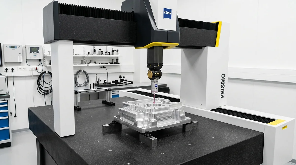
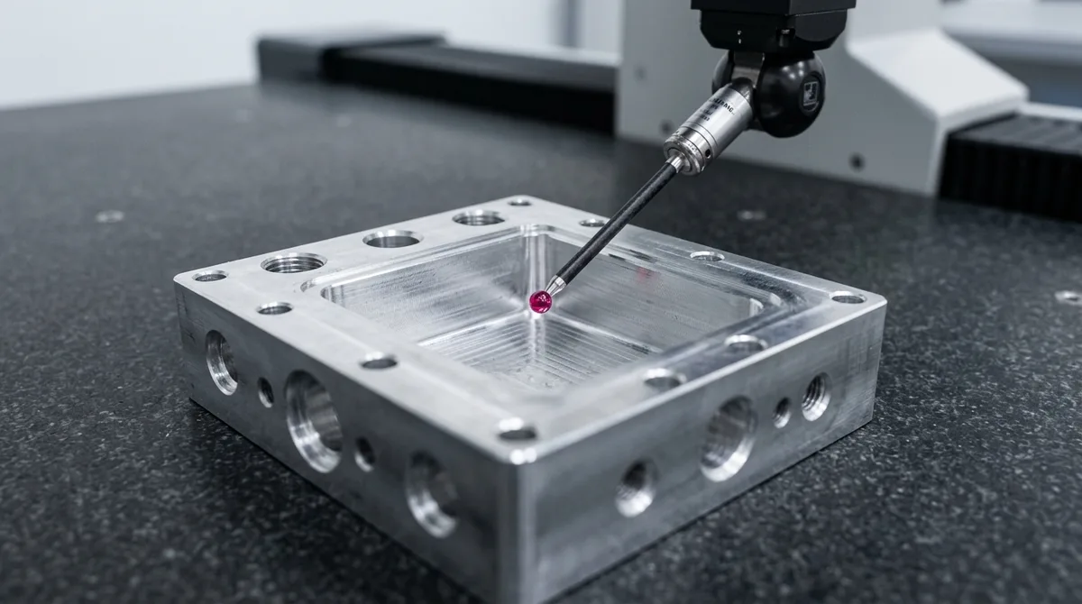
Precision coordinate metrology relies on an uncompromising mechanical foundation where monolithic granite guide ways and frictionless aerostatic air bearings eliminate dynamic stick-slip errors during automated multi-axis inspection. In our climate-controlled metrology laboratory, high-precision bridge-type coordinate measuring systems execute micron-level surface probing and bore center identification on critical aerospace and medical housings, validating geometric dimensions and true position tolerances against nominal CAD solids.
2. CMM Structural Architectures: Comprehensive Comparative Engineering
Metrology machine tool builders configure CMM structures across several mechanical topologies, each optimized for specific component envelopes, part weights, and dynamic accuracy requirements. Selecting the correct architecture ensures the measurement uncertainty budget remains significantly smaller than the workpiece tolerance zone.
Moving Bridge CMM Architecture
The moving bridge design is the undisputed workhorse of precision machine shops and quality inspection laboratories, accounting for over 75% of stationary CMM installations. In this layout, the workpiece rests stationary upon a heavy granite table while a rigid bridge structure (two vertical columns and a horizontal crossbeam) moves along the Y-axis. The carriage moves horizontally across the bridge (X-axis), and the vertical quill or ram moves vertically (Z-axis). Because the component mass is supported directly by the stationary granite table, part weight does not influence axis kinematics or induce dynamic structural deflection. Moving bridge machines provide outstanding volumetric accuracy, with standard measurement lengths ranging from 500 × 500 × 400 mm up to 2,000 × 3,000 × 1,500 mm and typical length uncertainties of E0,MPE = 1.2 + L/350 μm.
Fixed Bridge CMM Architecture
For ultra-high-precision reference metrology, master gage calibration, and micro-machined optical components, the fixed bridge architecture delivers the highest geometric rigidity. The bridge structure is permanently bolted or monolithically cast with the machine base, completely eliminating structural yawing and pitching moments induced by bridge acceleration. Instead, the granite worktable moves along the Y-axis on aerostatic bearings beneath the stationary bridge. While table load capacity is restricted (typically under 500 kg) to prevent dynamic inertia from altering axis velocity profiles, fixed bridge CMMs achieve extraordinary volumetric uncertainties below E0,MPE = 0.8 + L/400 μm.
Cantilever CMM Architecture
In a cantilever coordinate measuring machine, the vertical Z-axis quill is supported by a transverse arm supported on only one side by a rigid guide column. This open configuration leaves three sides of the granite table completely unobstructed, providing superior ergonomic access for manual part loading, rapid fixture swapping, and optical vision system integration. However, as the transverse carriage extends toward the outer limit of its travel, the cantilevered mass induces minor elastic bending moments that must be mapped and compensated via volumetric error software. Cantilever CMMs are primarily deployed for small precision micro-milled parts, medical implants, watchmaking components, and master plug/ring gage verification with travel ranges under 1,000 mm.
Gantry CMM Architecture
When measuring massive structural components—such as aircraft wing spars, aerospace fuselage bulkheads, large automotive stamping dies, and marine engine blocks—gantry CMMs provide massive volumetric capacity exceeding 3,000 × 6,000 × 2,000 mm. In a gantry configuration, two elevated parallel guide rails are mounted upon rigid concrete foundation pillars or floor-anchored steel columns. The bridge spans between these elevated rails, allowing heavy forklifts and overhead cranes to lower multi-ton components directly onto the floor plate between the rails. Dual synchronized linear motor drives on both rail sides ensure smooth, non-crabbing bridge traverse across long spans.
Horizontal Arm CMM Architecture
Horizontal arm machines feature a horizontal probe ram mounted to a vertical column traversing along a runway. Available in single-arm or dual-opposed synchronized configurations, horizontal arm CMMs provide deep horizontal reach into deep cavities, automotive body-in-white (BIW) structures, sheet metal door skins, and heavy engine blocks. While spatial accuracy is lower than bridge machines due to horizontal ram gravitational sag, their large measuring volume and side-entry access make them indispensable for automotive sheet metal assembly lines.
Articulated Portable CMM Arms
Portable articulated measuring arms depart from Cartesian guide rails entirely, utilizing multi-jointed linkages equipped with high-resolution optical rotary encoders at each articulation (typically 6 or 7 degrees of freedom). Fabricated from thermally stable, high-modulus carbon fiber tubes, articulated arms can be clamped directly to machine tool tables, granite plates, or shop-floor assembly fixtures. Equipped with either kinematic touch styli or high-speed non-contact 3D blue laser line scanners, portable arms deliver agile shop-floor inspection with volumetric uncertainties of ± 0.020 ~ 0.050 mm, enabling rapid CAD deviation color-mapping on large fabricated assemblies without transporting parts to the metrology lab.
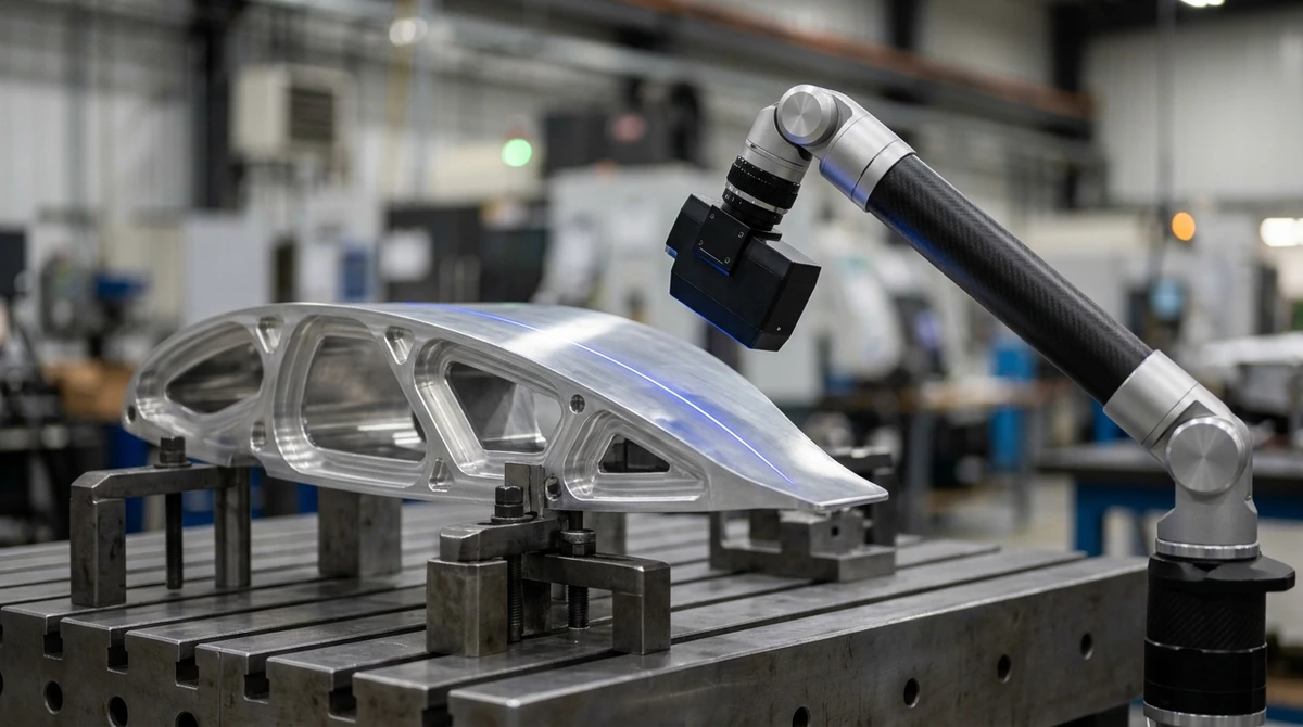
Shop-floor metrology demands agile dimensional verification where high-accuracy non-contact laser sensors capture thousands of surface data points per second directly at the manufacturing cell. Articulated portable measuring arms equipped with blue laser line triangulation scanners enable quality engineers to digitize complex curved surfaces, formed flanges, and CNC milled aerospace structural spars, comparing freeform aerodynamic contours directly against 3D CAD solids in real time.
| Architecture Type | Volumetric Range (X/Y/Z) | Length Uncertainty (E0,MPE) | Dynamic Rigidity | Thermal Sensitivity | Primary Industrial Application |
|---|---|---|---|---|---|
| Moving Bridge | 500 ~ 2,000 mm | 1.2 + L/350 μm | High (Symmetric) | Moderate (Granite base) | Precision CNC parts, engine blocks, aerospace housings |
| Fixed Bridge | 300 ~ 1,000 mm | 0.8 + L/400 μm | Maximum (Minimal bridge yaw) | Low (High thermal mass) | Calibration labs, master gages, optical lenses, micro-tooling |
| Cantilever | 300 ~ 800 mm | 1.5 + L/300 μm | Moderate (Asymmetric arm) | Moderate | Small electronic enclosures, medical implants, dental fittings |
| Gantry Frame | 2,000 ~ 10,000+ mm | 2.5 + L/250 μm | High (Elevated dual drive) | High (Requires foundation isolation) | Aircraft wing ribs, rocket fuel tanks, wind turbine hubs |
| Horizontal Arm | 1,500 ~ 6,000 mm | 10 + L/100 μm | Low (Cantilever sag) | High | Automotive Body-in-White (BIW), door skins, large weldments |
| Articulated Arm | 1,200 ~ 4,500 mm (Spherical) | ± 0.020 ~ 0.050 mm | Variable (Joint-dependent) | Low (Carbon fiber tubes) | In-situ machine tool verification, sheet metal weldments, laser scanning |
3. Tactile Probing Kinematics, Stylus Mechanics & Lobing Error Physics
The metrology sensor interface directly governs the fidelity of digitized coordinate data. Coordinate metrology utilizes two primary tactile sensor families: kinematic touch-trigger probes and continuous analog scanning probes, supplemented by non-contact optical triangulation sensors.
Kinematic Touch-Trigger Probes & The Physics of Lobing Error
Standard touch-trigger probes (such as the industry-benchmark Renishaw TP20) utilize a highly repeatable kinematic seating mechanism. Inside the probe body, a triangular spider plate connected to the stylus stem carries three cylindrical carbide rollers spaced 120° apart. Each roller rests across a pair of electrically conductive tungsten carbide balls, forming a series circuit of six electrical contact points. When the probe tip touches the part surface, contact force pivots the stylus, lifting at least one roller off its contact pair. The sudden break in electrical continuity triggers a hardware latching pulse that freezes the scale counter registers in the machine controller within microseconds.
However, kinematic touch-trigger probes suffer from an inherent physical characteristic known as pre-travel variation or probe lobing error. The mechanical trigger force required to pivot the stylus is anisotropic—it varies systematically depending on the horizontal approach angle relative to the internal triangular rollers:
- Maximum Trigger Force (Apex Vector): When the probe approaches directly in line with one of the three rollers, the roller acts as a direct pivot hinge, demanding maximum contact force (≈ 0.12 ~ 0.15 N) and causing higher stylus stem bending deflection before electrical unseating occurs.
- Minimum Trigger Force (Inter-Roller Vector): When the probe approaches midway between two rollers, the mechanism easily rocks across the roller gap, requiring minimal contact force (≈ 0.06 ~ 0.08 N) and minimal pre-travel deflection.
Plotted on a polar chart, this directional trigger force variance generates a characteristic triangular “three-lobed” error pattern with an amplitude of 0.5 ~ 1.5 μm. To counteract lobing error, CMM controllers perform qualification routines using a traceable master calibration reference sphere (typically grade 3 ruby or tungsten carbide with sphericity < 0.1 μm), establishing a mathematical 3D deflection map that offsets pre-travel error for each calibrated probing vector.
Piezoelectric Strain-Gauge Probes
To eliminate kinematic lobing error entirely, advanced probes (such as the Renishaw TP200) incorporate solid-state piezoelectric strain gauges positioned above the stylus mount. When contact occurs, the strain gauges detect microscopic structural bending forces (< 0.02 N, about 2 gf) well before the kinematic mechanism unseats. Because trigger sensing is decoupled from mechanical roller displacement, strain-gauge probes exhibit uniform, isotropic pre-travel in all directions (< 0.15 μm lobing variance), providing superior measurement repeatability with long styli and high-aspect-ratio extensions.
Continuous Analog Scanning Probes
While touch-trigger probes capture discrete coordinate points at 1 ~ 3 points per second, continuous analog scanning probes (such as Zeiss VAST or Renishaw SP25M) maintain continuous sliding contact along the workpiece surface, acquiring 500 ~ 2,000 calibrated points per second. These probes feature active measuring sensors with integrated linear variable differential transformers (LVDTs) or optical scales along internal X, Y, Z flexures, measuring actual stylus deflection while the CMM drives smoothly along nominal CAD curves. Continuous scanning is mandatory for comprehensive form metrology—revealing out-of-round waviness, lobing in bored holes, cylinder taper, and surface profile deviations that discrete 4-point circle routines completely miss.
Stylus Stem Mechanics & Cantilever Bending
The mechanical connection between the probe sensor and the contact sphere behaves as a structural cantilever beam under contact loading. The elastic bending deflection δstylus under contact force Fcontact is governed by classical beam mechanics:
Where Lstem is the stylus length, E is the Young’s modulus of the stem material, and dstem is the stem diameter. Notice the cubic dependence on length (L3): doubling the stylus length increases mechanical deflection by a factor of eight (23 = 8), dramatically multiplying pre-travel uncertainty. Therefore, metrologists select high-modulus materials to maximize rigidity:
- Tungsten Carbide (E ≈ 620 GPa): Standard choice for short-to-medium styli (< 50 mm); extremely rigid but heavy.
- Carbon Fiber (E ≈ 450 GPa, ρ≈ 1,550 kg/m3): The premier material for long extensions (100 ~ 600 mm); delivers high bending stiffness with minimal mass, preventing dynamic inertia droop on articulating probe heads.
- Ceramic (Al2O3, E ≈ 380 GPa): High thermal stability and electrical insulation with excellent structural stiffness.
- Stylus Ball Materials: Synthetic monocrystalline ruby (Al2O3) is standard due to exceptional hardness (2,000 HV) and sphericity. However, when continuously scanning pure aluminum alloys under contact pressure, adhesive chemical micro-pick-up occurs as aluminum atoms transfer to the ruby sphere, creating flat spots. For aluminum scanning, Silicon Nitride (Si3N4) or Zirconia (ZrO2) balls must be used to eliminate chemical affinity.
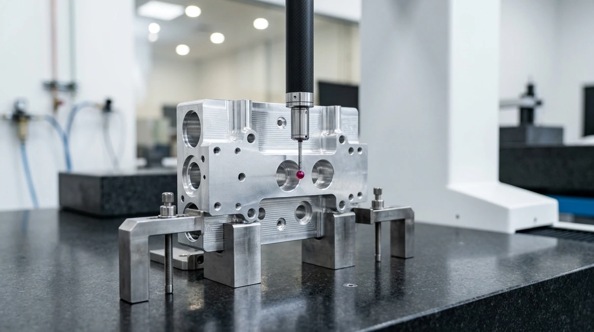
Multi-axis probing in deep component cavities requires rigid carbon-fiber extensions and motorized articulating probe heads capable of indexing at discrete angular increments without recalibration. In our quality control workflow, high-stiffness ruby styli navigate complex internal hydraulic passages, verifying vertical wall perpendicularity, cross-hole intersection depths, and inside corner fillet radii without shank collision.
| Probe Category | Sensing Mechanism | Sampling Rate | Lobing Pre-Travel Error | Recommended Stylus Material | Ideal Metrology Use Case |
|---|---|---|---|---|---|
| Kinematic Touch-Trigger | Mechanical 3-roller unseating circuit | 1 ~ 3 points/sec | 0.50 ~ 1.50 μm | Tungsten carbide stem, Ruby ball | Prismatic features, bolt holes, planar datums, general CNC milling |
| Strain-Gauge Touch | Piezoelectric resistive silicon strain gauges | 2 ~ 5 points/sec | < 0.15 μm (Isotropic) | Carbon fiber extension, Ruby / Zirconia | Long-reach probe builds (>100 mm), tight true position callouts |
| Active Analog Scanning | Continuous LVDT / optical inductive flexures | 500 ~ 2,000 points/sec | Negligible (Dynamic force feedback) | Silicon Nitride (Si3N4) for Al; Ruby for steel | Cylindricity, roundness, cam lobes, aerospace turbine blades, impellers |
| Non-Contact Optical Laser | Blue laser line triangulation / CMOS sensor | 100,000 ~ 1,000,000 pts/sec | N/A (Optical spot uncertainty ± 5 μm) | Optical anti-reflection matte coating | Organic freeform contours, sheet metal stampings, reverse engineering |
4. Metrology Environmental Control & Thermal Drift Dynamics
A coordinate measuring machine is only as reliable as the thermodynamic environment enclosing it. Under ISO 1 (Geometrical Product Specifications — Standard Reference Temperature for Geometrical Product Specification and Verification), all engineering drawing dimensions and GD&T tolerance boundaries are legally defined at exactly 20°C (68°F). Temperature deviations introduce severe physical expansion and contraction governed by the linear thermal expansion equation:
Where L0 is the nominal dimension, α is the material’s linear coefficient of thermal expansion (CTE), and ΔT = Tactual – 20°C is the temperature delta. To understand why environmental stabilization is mandatory, consider a CNC machined 6061-T6 aluminum aerospace chassis with a nominal length of L0 = 500.000 mm (α≈ 23.4 × 10⁻⁶/K). If measured on an unconditioned shop floor at 24°C (ΔT = +4°C), the component physically expands by:
A physical expansion of 46.8 μm completely consumes an entire ± 0.020 mm drawing tolerance band, causing an acceptable precision component to be erroneously rejected or a scrap component to pass inspection! Furthermore, differential thermal expansion between the machine structure and the workpiece introduces complex thermal gradients. While CMM optical scales utilize ultra-low-expansion substrates (such as Zerodur with α≈ 0.05 × 10⁻⁶/K) or quartz glass, the granite bed (α≈ 5.5 × 10⁻⁶/K) and aluminum/steel components expand at wildly divergent rates.
To ensure absolute measurement fidelity, precision metrology laboratories operate within strictly controlled environmental parameters:
- Target Ambient Temperature: Maintained at 20.0°C ± 0.5°C (for Class 1 labs) or ± 0.2°C (for master calibration labs) with vertical and horizontal air stratification gradients held below 0.2°C/meter.
- Relative Humidity: Regulated between 40% and 60% RH. Lower humidity (< 35%) induces electrostatic charge accumulation that attracts airborne dust to granite surfaces and styli; higher humidity (> 65%) promotes corrosion on hardened tool steel gages and optical mirrors.
- Thermal Soaking Protocols: Large billet components transferred from the CNC machining floor into the metrology room must undergo a mandatory thermal stabilization soaking period (minimum 4 to 12 hours depending on part thickness) until internal core temperatures equilibrate to 20.0°C.
- Active Real-Time Temperature Compensation: Modern CMM controllers integrate multi-channel PT100 contact thermistor sensors magnetically attached to machine axis scales and clamped directly to the workpiece. The controller software continuously samples temperatures, computing dynamic mathematical expansion compensation in real time to correct raw scale counts back to the 20°C baseline.
- Vibration Isolation: The entire granite CMM foundation is supported on pneumatic active air isolators with natural resonance frequencies tuned below 2.5 Hz, shielding sensitive stylus contacts from low-frequency vibrations generated by nearby heavy punch presses, fork trucks, and high-speed CNC machining centers.
| Material Designation | CTE α (10-6/K) | Expansion on 300 mm per 2°C ΔT | Thermal Conductivity (W/m·K) | Mandatory Soaking Protocol (20°C) |
|---|---|---|---|---|
| Aluminum 6061-T6 / 7075-T651 | 23.4 ~ 23.6 | +14.1 μm | 130 ~ 167 (Rapid equalization) | 4 ~ 6 hours (Granite soaking table) |
| Austenitic Stainless Steel (304 / 316L) | 16.0 ~ 16.5 | +9.9 μm | 16.2 (Low conduction) | 6 ~ 8 hours (Core temperature lag) |
| Tool Steel / Alloy Steel (P20 / 4140) | 11.5 ~ 12.2 | +7.1 μm | 35 ~ 42 | 6 ~ 10 hours (Heavy mold inserts) |
| Titanium Ti-6Al-4V (Grade 5) | 8.6 ~ 9.0 | +5.3 μm | 7.2 (Very poor conductor) | 8 ~ 12 hours (Prevent surface/core delta) |
| Invar 36 (Precision Alloy) | 1.2 ~ 1.5 | +0.8 μm | 10.5 | 2 ~ 4 hours (Optical tooling) |
| Engineering PEEK / POM Plastic | 45.0 ~ 110.0 | +27.0 ~ 66.0 μm | 0.25 (Extreme insulator) | 12 ~ 24 hours (Thermal & humidity soak) |
5. ASME Y14.5 & ISO 1101 GD&T Alignment: Mathematical Mechanics
Raw coordinate data points collected by a CMM exist solely in the machine’s internal axis coordinate system. Before dimensional tolerances and geometric callouts can be evaluated, the metrologist must align the digitized physical part into a Datum Reference Frame (DRF) aligned with the workpiece engineering drawing per ASME Y14.5-2018 or ISO 1101.
The 3-2-1 Alignment Principle
To mathematically constrain all six spatial degrees of freedom (three translations: Tx, Ty, Tz; three rotations: Rx, Ry, Rz), coordinate metrology implements the classical 3-2-1 alignment hierarchy:
- Primary Datum A (Planar Spatial Leveling): Probing a minimum of three non-collinear points on the primary functional mounting face establishes a mathematical plane. The normal vector of this plane locks the orientation of the spatial coordinate system, constraining two rotational degrees of freedom (pitch Rx and roll Ry) and setting the translational origin along the vertical axis (Tz). Three spatial degrees of freedom are fully constrained.
- Secondary Datum B (Planar / Linear Rotation): Probing two spaced points along an intersecting perpendicular datum edge or bore centerline creates a reference line. Projected onto the primary datum plane, this line constrains the final rotational degree of freedom (yaw Rz) and sets the secondary translational origin (Ty). Two additional degrees of freedom are constrained (five total).
- Tertiary Datum C (Origin Stop): Probing a single contact point against an orthogonal stop face, stop pin, or intersecting shoulder establishes the final translational origin (Tx), completing the total six-degree-of-freedom constraint (6 DOF).
CAD-Direct Alignment & Iterative / RPS Alignments
When inspecting complex 5-axis contoured aerospace components, automotive sheet metal stampings, or organic turbine impellers that lack flat orthogonal datums, metrologists execute an Iterative Alignment or Reference Point System (RPS). Six or more discrete surface points are probed directly on nominal CAD coordinates. The CMM software executes a least-squares transformation algorithm, iteratively rotating and translating the coordinate system in 3D space until the measured deviations between probe touches and nominal CAD surfaces converge to zero within specified thresholds (< 0.005 mm).
Mathematical Feature Fitting Algorithms
Once aligned, the metrology software fits idealized geometric primitives (planes, cylinders, cones, spheres) through discrete measured point clouds. The mathematical algorithm selected profoundly influences reported tolerance results:
- Least Squares Fitting (Gaussian / LSQ): The mathematical standard in most metrology routines. LSQ calculates feature parameters by minimizing the sum of the squared radial or perpendicular deviations of all measured points: min ∑i=1n (ri – R)2 Because LSQ squares deviations, it produces a stable, average feature geometry that balances positive and negative surface variations. However, it effectively averages out localized micro-peaks and valleys.
- Minimum Zone Fitting (Chebyshev / MZ): Minimum Zone evaluates the absolute peak-to-valley boundary, finding two concentric cylinders (for a bore) or two parallel planes (for a face) that enclose all measured data points with minimal radial or linear separation: min ( max(ri) – min(ri) ) Minimum Zone represents the direct mathematical embodiment of ASME Y14.5 form tolerance envelopes (flatness, straightness, roundness, cylindricity), ensuring that no localized burr, tool mark, or chatter wave violates the drawing boundary.
- Maximum Inscribed Cylinder (MIC): Calculates the largest perfect cylinder that fits entirely inside an internal hole without penetrating any measured material point. MIC simulates the actual assembly fit of a precision go-gage pin or bearing shaft.
- Minimum Circumscribed Cylinder (MCC): Calculates the smallest perfect cylinder that encloses all points of an external shaft without penetrating the material. MCC simulates the mating fit of a bearing housing or bushing.
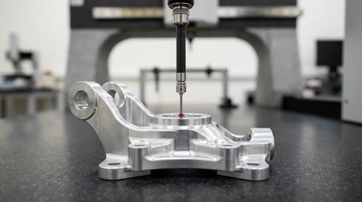
Establishing an uncompromising Datum Reference Frame requires measuring critical functional surfaces on black granite plates before evaluating downstream geometric callouts. On precision 5-axis automotive suspension uprights and aerospace brackets, tactile probe routines touch primary mounting planes and critical bearing bores, evaluating ASME Y14.5 true position, perpendicularity, and coaxiality tolerances.
6. CMM Calibration, Verification & 21 Geometric Error Parameters
To ensure international measurement traceability and legal compliance, coordinate measuring machines undergo rigorous periodic calibration and reverification in accordance with ISO 10360-2 (Acceptance and Reverification Tests for Coordinate Measuring Machines).
ISO 10360-2 Volumetric Length Measurement Error
The core performance specification of any CMM is its maximum permissible error of length measurement, denoted as E0,MPE. The error boundary is mathematically defined by a linear formula:
Where a is a constant representing fixed electronic and probing uncertainty (μm), L is the measured distance along the axis or spatial diagonal (mm), and K is a dimensionless divisor indicating scale accuracy across distance. For example, a high-end bridge CMM specified at E0,MPE = 1.5 + L/350 μm guarantees the following measurement boundaries:
- At a short length of L = 50 mm: E0,MPE = 1.5 + 50/350 = 1.64 μm.
- At an extended stroke of L = 700 mm: E0,MPE = 1.5 + 700/350 = 3.50 μm.
ISO 10360-2 mandates that calibrated Zerodur step gauges, ceramic gauge blocks, or laser tracking interferometers be measured across seven distinct spatial directions: along the three primary Cartesian axes (X, Y, Z) and across all four volumetric body diagonals. Five different lengths are measured three times each in every direction (105 total length measurements), and every single measurement must fall inside the E0,MPE envelope.
The 21 Kinematic Geometric Error Parameters
In physical space, no machine tool structure is perfectly straight, flat, or orthogonal. A three-axis Cartesian CMM possesses exactly 21 geometric error parameters that dynamically distort the spatial position of the probe tip:
- 6 Degrees of Error per Axis × 3 Axes = 18 Errors:
- 1 Linear Positioning Error: Scale calibration error along the axis (δx(x), δy(y), δz(z)).
- 2 Straightness Errors: Lateral guide way deviance in two orthogonal directions (δy(x), δz(x) for X-axis).
- 3 Angular Errors: Rotational tilt during axis carriage traverse: Pitch (θy(x)), Yaw (θz(x)), and Roll (θx(x)).
- 3 Inter-Axis Squareness Errors: Perpendicularity deviations between the three orthogonal planes (αxy, αyz, αzx).
Modern high-precision CMM controllers overcome these 21 mechanical imperfections via Volumetric Error Compensation (CAA – Computer Aided Accuracy). During factory calibration, multi-beam laser interferometers and electronic levels map the complete 21-parameter spatial error matrix into the controller. In real time, the CMM controller dynamically calculates Abbe error offsets and angular rotations, shifting the electronic coordinate registers by fractions of a micron to cancel physical machine distortions.
| Kinematic Axis | Positioning Error | Horizontal Straightness | Vertical Straightness | Angular Errors (Pitch / Yaw / Roll) | Inter-Axis Squareness |
|---|---|---|---|---|---|
| X-Axis (Carriage) | δx(x) (Scale Pitch) | δy(x) (Horizontal Bow) | δz(x) (Vertical Sag) | θy(x) Pitch, θz(x) Yaw, θx(x) Roll | αxy (X-Y Squareness) |
| Y-Axis (Bridge) | δy(y) (Scale Pitch) | δx(y) (Horizontal Bow) | δz(y) (Granite Flatness) | θx(y) Pitch, θz(y) Yaw, θy(y) Roll | αyz (Y-Z Squareness) |
| Z-Axis (Quill) | δz(z) (Scale Pitch) | δx(z) (X-Deflection) | δy(z) (Y-Deflection) | θx(z) Pitch, θy(z) Yaw, θz(z) Roll | αzx (Z-X Squareness) |
7. In-House CNC Machining Integration & First Article Inspection (FAIR)
Coordinate metrology achieves its highest commercial value when tightly coupled with precision production machining. Rather than serving merely as an end-of-line gatekeeper, an in-house CMM laboratory creates a closed-loop engineering feedback system that optimizes CNC machining operations, preserves tool life, and eliminates batch scrap.
Closed-Loop Metrology Feedback in Machining
In our precision manufacturing facility, high-speed 3-axis and 4-axis vertical machining centers (VMCs)—which perform the bulk (75% ~ 85%+) of precision enclosure, manifold, and bracket production—are coupled with wireless spindle touch probes (such as Renishaw OMP60) for automated work coordinate system (WCS) datum setting and in-process stock monitoring. Meanwhile, simultaneous 5-axis machining centers are deployed strategically for complex curved impellers, multi-axis turbine blades, and multi-angle aerospace brackets.
When high-precision batches require true position tolerances under ± 0.015 mm, parts are transitioned from the CNC machining centers to the climate-controlled CMM laboratory. Automated parametric inspection programs analyze critical bore diameters, center-to-center distances, and face perpendicularity. If CMM trend analysis detects a gradual 0.006 mm (6 μm) bore contraction caused by carbide boring tool insert flank wear, the metrology software exports automated tool offset compensation files directly back to the CNC machine controller via DNC network, adjusting tool wear registers before any component breaches tolerance limits.
First Article Inspection Report (FAIR / FAI) Protocol
For mission-critical hardware in aerospace, medical diagnostics, robotics, and defense sectors, production sign-off requires a comprehensive First Article Inspection Report (FAIR). The FAIR protocol enforces full traceability:
- 100% Ballooned Drawing Correlation: Every dimension, GD&T callout, thread depth, surface finish specification, and drawing note on the customer’s 2D PDF engineering drawing is assigned a sequential numbered bubble or balloon.
- Parametric CMM Data Cross-Referencing: The CMM inspection program is architected so that each measured feature directly correlates to the balloon number on the drawing.
- Comprehensive Data Sheet Generation: The final metrology report presents:
- Nominal CAD Dimension
- Upper Specification Limit (USL) & Lower Specification Limit (LSL)
- Actual Measured Dimension
- Deviation / Error from Nominal
- Out-of-Tolerance Indicator (Delta flags)
- Statistical Process Metrics (Cpk / Ppk capability where required)
- Material & Surface Finish Documentation: The FAIR dossier is bundled with raw material mill test reports (MTR), heat treatment hardness test logs, and ASTM B117 salt spray or anodizing thickness inspection records, providing complete component pedigree.
Manufacturing Reality: Practical Tolerancing Standards
A rigorous understanding of metrology physics prevents costly over-tolerancing. In precision manufacturing, standard prismatic features and general non-critical dimensions follow ISO 2768-mK general tolerances. Critical mating features—such as bearing press-fit journals, dowel pin locations, and O-ring sealing gland depths—are explicitly dimensioned with bilateral tolerances of ± 0.010 ~ ± 0.020 mm. For ultra-precision applications requiring sub-micron finishes and ± 0.005 mm limits, specialized slow-wire EDM and optical profile grinding operations are paired with climate-stabilized CMM verification. By aligning design intent with proven CMM measurement uncertainty budgets, engineering teams achieve optimal mechanical performance without inflating manufacturing costs.
A Coordinate Measuring Machine (CMM) is an electro-mechanical metrology system that measures the 3D physical geometry of an object. Moving along three orthogonal Cartesian axes (X, Y, Z), it records discrete spatial coordinate points on component surfaces using tactile ruby probes or optical laser sensors, mathematically computing dimensional characteristics, surface contours, and ASME Y14.5 GD&T tolerances (such as flatness, cylindricity, perpendicularity, and true position) against nominal 3D CAD models.
Touch-trigger probes use internal kinematic roller contacts or piezoelectric strain gauges to capture discrete coordinate points (1 to 5 points per second) when contact is made. In contrast, analog continuous scanning probes maintain constant sliding contact along the workpiece, measuring continuous deflection forces to capture 500 to 2,000 points per second. Continuous scanning is essential for comprehensive form analysis, revealing out-of-round waviness, lobing, and surface profile errors that discrete point probing can miss.
Per ISO 1, all international engineering drawings and GD&T specifications are legally defined at 20°C (68°F). Thermal expansion follows the formula ΔL = L0 · α · ΔT. For instance, aluminum expands by approximately 23.4 μm/m per °C; an uncontrolled temperature shift of 4°C will expand a 500 mm aluminum billet by 46.8 μm, completely exceeding a ±0.010 mm tolerance band. Maintaining a stabilized 20°C ± 0.5°C environment prevents thermal measurement distortion.
E0,MPE represents the Maximum Permissible Error of length measurement under ISO 10360-2. It is expressed as a linear formula: E0,MPE = a + L/K [μm], where ‘a’ is a constant baseline error in microns and ‘K’ is a divisor representing error growth over length ‘L’ in millimeters. For example, a machine with E0,MPE = 1.5 + L/350 μm guarantees that measured length errors will not exceed 1.64 μm over 50 mm, or 3.50 μm over a 700 mm distance.
Least Squares (LSQ) fitting calculates geometry by minimizing the sum of squared deviations from all measured points, producing a stable average feature location. Minimum Zone (MZ / Chebyshev) fitting minimizes the peak-to-valley spread, determining the minimum width envelope that encloses all points. Minimum Zone strictly complies with ASME Y14.5 form tolerance definitions, ensuring no single peak or valley violates boundary envelopes.
Validate Your Precision Machined Components with CMM Metrology
AS Prototypes integrates advanced multi-axis CNC machining with comprehensive climate-controlled CMM metrology inspection. Our in-house engineering team provides complete First Article Inspection Reports (FAIR), ballooned drawing traceability, and full GD&T verification for mission-critical aerospace, automotive, medical, and industrial prototypes. Upload your 3D CAD models (STEP, IGES) and 2D engineering drawings for a rigorous DFM analysis within 24 hours.