Quick Engineering Takeaways (BLUF)
- Optimal Punch-to-Die Clearance: Governed by material ultimate shear strength and sheet thickness (t). Standard clearances range from 5% to 8% per side for 5052/6061 aluminum, 7% to 10% for mild carbon steel (SPCC), and 10% to 14% for austenitic stainless steel (304/316L) to ensure collinear micro-crack propagation and minimize burr height.
- K-Factor & Neutral Axis Physics: Plastic bending causes the neutral axis to shift inward toward the compressive surface, shifting the K-factor between 0.30 (tight coining) and 0.45 (air bending). Exact CAD flat pattern blank sizing requires calculating Bend Allowance (BA) and Bend Deduction (BD) with directional rolling grain considerations.
- Springback Mechanics & Tooling Mitigation: Elastic strain recovery increases with the yield-to-modulus ratio (σ_y / E). High-strength stainless steels exhibit 6° to 10° of angular springback, neutralized through die overbending, root coining beads, and localized stress-relief grooving.
- Deep Drawing Thresholds: Governed by the Limiting Drawing Ratio (LDR = D_blank / D_punch ≤ 1.8 to 2.2). First-stage reduction must stay under 40% to 45%, supported by optimized blank holder force (BHF) to eliminate circumferential flange wrinkling and cup bottom tearing.
- Progressive Tool Steel Metallurgy: High-stress punches and die inserts leverage vacuum-hardened DC53 (60~62 HRC) or powder-metallurgy CPM 1V/Vanadis 4 Extra, paired with PVD TiCN or AlCrN coatings to eliminate galling and adhesive pickup during multi-million-cycle runs.
- Metrological Verification: Thin-gauge stampings require free-state GD&T verification per ASME Y14.5M, using articulated 3D blue laser scanning arms (±0.015 mm accuracy) to generate real-time CAD color deviation heat maps across contoured surfaces.
In automotive engineering, consumer electronics, telecommunications, and industrial equipment manufacturing, the demand for lightweight, mechanically rigid, and cost-effective enclosures is ubiquitous. While multi-axis CNC milling excels at producing complex monolithic prototypes with low tooling entry costs, it becomes economically unviable when production volumes scale into thousands or hundreds of thousands of parts. For thin-gauge enclosures, structural brackets, electrical busbars, and EMI shielding cans, precision sheet metal stamping stands as the premier high-speed, high-repeatability manufacturing process.
However, successful sheet metal stamping is not simply a matter of crushing sheet metal between two blocks of steel. Stamping is an exacting science of non-linear plastic deformation, shearing boundary mechanics, material anisotropy, and springback physics. Transitioning a prototype sheet metal bracket into high-volume progressive stamping requires a disciplined understanding of punch-to-die cutting clearances, neutral axis shift (K-factor), deep drawing ratios (LDR), and rapid tooling strategies that bridge the gap between low-volume prototyping and mass manufacturing. This comprehensive engineering guide examines the mechanics of metal stamping, progressive die design, material metallurgy, and metrological inspection.
1. The Mechanics of Sheet Metal Forming: Shearing Boundary Physics & Clearance Dynamics
Sheet metal stamping encompasses a diverse spectrum of mechanical operations, broadly categorized into separation (cutting) and non-cutting plastic forming processes. Achieving microscopic cut edge integrity begins with understanding how tool steel cutting edges interact with the metallurgical structure of the workpiece under dynamic shear loading.
1.1 Shearing Mechanism & Edge Morphology
When a hardened punch penetrates sheet metal supported by a die opening, the material undergoes four distinct physical deformation phases that leave a characteristic edge cross-section:
- Rollover (Draw-in Zone): During initial punch impact, elastic bending and localized plastic tensile stresses cause the top surface of the sheet to round inward toward the cut line. Excessive rollover indicates either oversized die clearance or ultra-ductile alloy conditions.
- Burnish (Cut Band / Shear Zone): As the punch penetrates deeper into the sheet, the precision ground cutting edges shear the metal smoothly, producing a bright, vertical, highly polished band. In high-precision functional stamping, the burnish band typically represents 30% to 55% of the total sheet thickness. In fine-blanking operations utilizing triple-action presses, the burnish band reaches 90% to 100% of material thickness.
- Fracture Zone: When internal shear stresses exceed the ultimate shear strength of the alloy, micro-cracks initiate simultaneously at the upper punch edge and lower die cutting edge. In an aligned tool, these micro-cracks propagate diagonally toward each other until they meet collinear, cleanly separating the slug from the strip. The resulting fracture surface exhibits a rough, matte, slightly tapered texture.
- Burr: At the final microsecond of mechanical fracture, plastic elongation at the exit edge forms a sharp microscopic projection along the bottom perimeter of the blank. Excessive burr height (>10% of sheet thickness) causes assembly interference, short-circuits in electrical terminals, and operator handling hazards.
1.2 Punch-to-Die Clearance Optimization
Punch-to-die clearance (c) is defined as the total radial gap between the punch perimeter and the die cavity opening, expressed as a percentage of sheet thickness (t) per side (c = (D_die – D_punch) / 2):
- Optimal Clearance Window: Optimal clearance aligns the micro-cracks originating from the punch edge and the die cutting edge at identical angles. The cracks propagate and intersect cleanly, minimizing punching force, eliminating secondary shear steps, and producing a burr height under 5% of thickness.
- Excessive Clearance (c > 14%~18% t): When the clearance gap is too wide, tensile tearing dominates before shearing completes. The sheet is pulled into the die opening, creating an excessively deep rollover zone, a rough, heavily tapered fracture surface, and tall, sharp edge burrs that require secondary vibratory deburring.
- Insufficient Clearance (c < 4%~6% t): When clearance is overly tight, the micro-cracks miss each other and fail to intersect. Instead, the material between the crack paths must be sheared a second time by the descending punch. This generates a secondary burnish band, double-fracture steps, massive tool friction, and explosive punching force spikes that rapidly chip hardened tool steel corners.
1.3 Shearing Force, Stripping Force & Staggered Punch Kinematics
Accurate press tonnage calculation protects press crankshaft bearings and prevents tool deflection. The theoretical peak shearing force (F_shear) required to punch a perimeter (L) through sheet thickness (t) is modeled as:
Where τ_shear is the ultimate shear strength of the alloy (typically 70% to 80% of ultimate tensile strength σ_uts), and C_shear is a clearance and lubrication factor (1.0 for flat punches). When all punches strike the metal strip simultaneously, the instantaneous tonnage shock can exceed the structural rating of the stamping press.
To eliminate tonnage shock, tool designers employ two core engineering techniques:
- Staggered Punch Lengths: By stepping punch lengths by 1.0t to 1.5t, individual punches enter the material sequentially rather than concurrently. This flattens the tonnage spike across the press stroke, cutting instantaneous peak load by 30% to 50%.
- Angular Shear Grind (Bevel / Rooftop Shear): Grinding a shear angle (θ = 1° to 3°, or roof height equal to 1.0t) on the punch face transforms punching into a progressive scissor-cutting action. This cuts maximum piercing tonnage by 25% to 40% while dampening mechanical vibration.
- Stripping Force Dynamics: As the punch retracts, lateral elastic compression from the surrounding sheet grips the punch shank. The stripper plate must provide active stripping force (F_strip = 0.05 to 0.15 × F_shear) via heavy-duty nitrogen gas springs or precision mechanical die springs to retract the punch without pulling or distorting the strip skeleton.
| Alloy & Temper Specification | Tensile Strength σ_uts (MPa) | Shear Strength τ_shear (MPa) | Per-Side Clearance c (% of t) | Expected Burnish Band | Typical Burr Height |
|---|---|---|---|---|---|
| Aluminum 1050-O (Pure Al) | 70 ~ 95 | 55 ~ 65 | 4.0% ~ 6.0% | 45% ~ 60% t | < 4% t |
| Aluminum 5052-H32 | 210 ~ 260 | 140 ~ 160 | 5.0% ~ 7.5% | 35% ~ 50% t | < 5% t |
| Aluminum 6061-T6 | 290 ~ 310 | 190 ~ 210 | 7.0% ~ 9.0% | 25% ~ 35% t | < 6% t |
| Mild Carbon Steel (SPCC / 1008) | 270 ~ 370 | 190 ~ 260 | 7.0% ~ 10.0% | 30% ~ 45% t | < 5% t |
| Galvanized Steel (SECC / SGCC) | 270 ~ 390 | 200 ~ 270 | 7.5% ~ 10.5% | 30% ~ 40% t | < 6% t |
| Austenitic Stainless (SUS304) | 520 ~ 720 | 380 ~ 500 | 10.0% ~ 13.5% | 20% ~ 35% t | < 7% t |
| Austenitic Stainless (SUS316L) | 480 ~ 680 | 360 ~ 470 | 10.0% ~ 14.0% | 25% ~ 35% t | < 7% t |
| Spring Stainless (SUS301-1/2H) | 930 ~ 1100 | 680 ~ 800 | 12.0% ~ 16.0% | 15% ~ 25% t | < 8% t |
| Cartridge Brass (C2600 / CuZn30) | 310 ~ 440 | 210 ~ 290 | 6.0% ~ 8.5% | 40% ~ 55% t | < 4% t |
| Phosphor Bronze (C5191 / CuSn6) | 490 ~ 650 | 340 ~ 450 | 7.0% ~ 9.5% | 30% ~ 45% t | < 5% t |
2. Bending Kinematics, Neutral Axis Shift & Springback Compensation
When sheet metal bends around a die radius, the stress profile across the sheet thickness is non-linear and divided into two opposing mechanical fields: the inner fiber undergoes compressive shortening while the outer fiber undergoes intense tensile elongation.
2.1 Neutral Axis Relocation & Mathematical Blank Expansion
Between the tensile and compressive zones lies the Neutral Axis, where fiber length remains unchanged after deformation. In an unbent flat strip, the neutral axis sits exactly at sheet midthickness (0.50t). However, under plastic bending, plastic flow in tension is accompanied by cross-sectional thinning (Poisson necking), causing the neutral axis to migrate inward toward the concave compressive surface:
- K-Factor (K = t_neutral / t): The K-factor defines the shifted position of the neutral axis relative to total thickness. For large air-bending radii (R > 3t), K approaches 0.45 to 0.48. For tight bottoming and coining (R ≤ 1.0t), intense plastic flow pulls the neutral axis inward, dropping K to 0.30 to 0.35.
- Bend Allowance (BA): Represents the true arc length along the shifted neutral axis through bend angle θ (in degrees):BA = (π / 180) × θ × (R_inner + K × t)
- Outside Setback (OSSB): The linear distance from the apex of the outer bend intersection to the tangent point of the bend arc:OSSB = tan(θ / 2) × (R_inner + t)
- Bend Deduction (BD): The exact dimension subtracted from the sum of individual flange lengths to calculate the true flat blank length (L_flat = Flange_1 + Flange_2 – BD):BD = 2 × OSSB – BA
2.2 Material Anisotropy: Grain Direction & Micro-Fissuring
Cold-rolled sheet metal possesses pronounced directional mechanical properties resulting from rolling-induced crystallographic texture. Bending parallel to the rolling grain direction (Longitudinal Bending) concentrates tensile strain across elongated grain boundaries, severely degrading outer fiber ductility and inducing “orange peel” roughening or microscopic cracks.
In contrast, bending transverse (perpendicular) to the grain direction distributes tensile loads across continuous grain boundaries, allowing substantially tighter inside bend radii without cracking. When progressive die strip nesting requires bends in multiple orthogonal axes, strip layout engineers orient the blank at a 45° bias angle to the rolling direction to balance formability across all flanges.
2.3 Elastic Springback Mechanics & Tooling Countermeasures
Upon punch retraction, the release of external forming forces allows internal residual stresses to relax elastically. The compressed inner fibers expand while the stretched outer fibers contract, causing the final included bend angle to open up (Δθ). The magnitude of elastic springback is mathematically governed by the yield-to-modulus ratio (σ_y / E) and relative bend radius (R / t):
In high-strength alloys (such as SUS301 full-hard, 17-7PH stainless, or Ti-6Al-4V), springback can exceed 5° to 10°, demanding active tooling compensation strategies:
- Angular Overbending: The punch and die angle are ground sharper than the nominal drawing requirement (α_punch = 90° – Δθ). When the part springs open upon ejection, it settles precisely at the target 90° design dimension.
- Bottoming Coining Beads (Stress Relief Punching): By introducing a sharp protruding bead (radius 0.3~0.5 mm) at the nose of the forming punch, concentrated plastic compression is applied directly to the inner bend radius. This forces the compressive zone into plastic yielding, eliminating elastic tension-compression residual moments and locking the flange angle in place.
- Relief Undercut Grooving: For heavy-gauge plate or high-strength bracket corners, shallow CNC grooving or pre-notching along the inner bend line reduces effective local thickness (t_local = 0.6t), slashing the required bending tonnage and constraining springback to ±0.25°.
| Alloy & Temper Condition | Yield σ_y / Modulus E | Transverse R_min (⊥ Grain) | Longitudinal R_min (|| Grain) | Air-Bending Springback (Δθ) | Tooling Compensation Method |
|---|---|---|---|---|---|
| Aluminum 5052-H32 | 2.7 × 10¯³ | 0.5 × t | 1.0 × t | 1.0° ~ 2.0° | 1.5° Overbend / Coined radius |
| Aluminum 6061-T6 | 4.0 × 10¯³ | 1.5 × t | 2.5 × t | 2.5° ~ 4.5° | 3.0° Overbend / Form in O-temper |
| Mild Carbon Steel (SPCC) | 1.0 × 10¯³ | 0.2 × t | 0.5 × t | 0.5° ~ 1.5° | Bottoming coining / 1.0° Overbend |
| Austenitic Stainless (304) | 1.4 × 10¯³ | 0.8 × t | 1.5 × t | 2.0° ~ 3.5° | 2.5° Overbend + Punch relief groove |
| Spring Stainless (301-Full Hard) | 5.2 × 10¯³ | 3.0 × t | 5.0 × t | 6.0° ~ 10.0° | 8.0° Overbend + Coining pressure pad |
| Beryllium Copper (C17200-1/2H) | 4.6 × 10¯³ | 1.2 × t | 2.0 × t | 3.0° ~ 5.5° | Form in ductile state → Age-harden |
3. Deep Drawing Mechanics, Limiting Drawing Ratio (LDR) & Formability
Deep drawing forces a flat blank into a hollow contoured cup or cylindrical enclosure through coordinated punch descent into a matched die cavity. Unlike simple bending where strain is primarily localized along a 1D axis, deep drawing induces a complex bi-axial stress state: the flange undergoes radial tensile drawing stress combined with severe circumferential (hoop) compressive stresses.
3.1 Limiting Drawing Ratio (LDR) & Sequential Reductions
The formability threshold of a sheet metal alloy in deep drawing is characterized by its Limiting Drawing Ratio (LDR), defined as the maximum ratio of initial blank diameter (D_blank) to punch diameter (D_punch) that can be drawn without bottom rupture:
When the required component depth produces an LDR exceeding 2.0, attempting to form the shell in a single press stroke induces tensile stresses at the cup bottom radius that exceed the ultimate tensile strength of the metal, causing catastrophic bottom blowout. Production of deep cans, motor housings, and cylindrical sensor shields requires multi-stage progressive redrawing:
- First Draw Station: Reduction ratio m_1 = d_1 / D_blank = 0.55 to 0.60 (representing a 40% to 45% diameter reduction).
- Second Draw Station: Reduction ratio m_2 = d_2 / d_1 = 0.75 to 0.80 (20% to 25% diameter reduction).
- Third Draw Station: Reduction ratio m_3 = d_3 / d_2 = 0.82 to 0.85 (15% to 18% diameter reduction).
- Intermediate Annealing: Work-hardening alloys (such as austenitic stainless steels 304/316) require intermediate continuous vacuum annealing (1050°C with hydrogen rapid quench) between draw stations to recrystallize the austenitic grain structure and restore elongation.
3.2 Blank Holder Force (BHF) & Draw Bead Restraint
As the blank is drawn into the die, the circumference of the outer flange continuously shrinks. This circumferential compression creates intense instability: if unconstrained, the sheet will buckle into severe waves and wrinkles. The blank holder ring (binder plate) applies controlled vertical pressure to clamp the outer flange:
- Wrinkling Failure Boundary: If Blank Holder Force is insufficient, material buckles into the die throat, causing severe wrinkles that jam the die or fracture the cup wall.
- Tearing Failure Boundary: If Blank Holder Force is excessive, high interfacial friction prevents the material from slipping into the die. The punch stretches the bottom wall until tensile necking and tearing occur at the punch nose radius (R_punch).
- Draw Bead Engineering: In non-symmetrical, rectangular, or irregular drawn shells, metal flows much faster along flat edges than at tight corners. Tool engineers machine round, square, or stepped draw beads (bead height 3.0~6.0 mm) into the blank holder surfaces. Forcing the sheet to bend and unbend through the bead creates targeted back-tension, equalizing metal flow velocities across the entire perimeter.
- Ironing Operations: In deep-drawn motor cans and battery sleeves, secondary ironing dies with punch-to-die clearances tighter than incoming sheet thickness (c_iron = 0.85t to 0.92t) deliberately thin the cylindrical cup wall. Ironing produces uniform wall thickness (±0.010 mm) while burnishing the surface to a mirror finish (Ra < 0.4 μm).
4. Progressive Die Architecture, Strip Layout & Tool Metallurgy
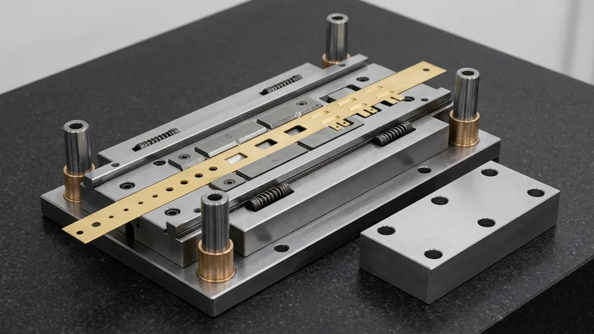
When production volumes scale from thousands to millions of units, progressive stamping dies deliver unparalleled production velocity, dimensional repeatability, and minimal labor cost per part. A progressive die performs multiple distinct operations—piercing, notching, pilot locating, forming, coining, and blanking—simultaneously at separate stations during each stroke of the press.
4.1 Progressive Strip Layout & Carrier Ribbon Kinematics
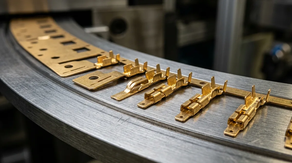
The foundation of progressive die design is the strip progression layout. The coiled strip is indexed forward by a servo roll feeder at a fixed pitch (progression step) with micron-level repeatability:
- Station 1 – Pilot Piercing: High-precision circular pilot holes (typically Ø2.000 mm to Ø4.000 mm, ±0.010 mm) are pierced along the outer carrier borders of the strip.
- Station 2 – Pilot Pin Registration: Hardened bullet-nosed pilot pins mounted on the upper die enter the pilot holes 1.5 to 2.0 mm before cutting punches strike the sheet. The press feed rolls enter a mechanical “feed release” micro-dwell, allowing the tapered pilot pins to pull the strip into exact alignment (±0.010 mm registration) across all subsequent die stations.
- Station 3 – Profile Notching & Blanking: Punches trim away scrap metal surrounding the part geometry, freeing the flanges while leaving the component securely tethered to the carrier web. Carrier web width must exceed 1.5× to 2.0× material thickness to resist bending deflection as the strip advances.
- Station 4 – Multi-Stage Bending & Coining: Complex vertical flanges are formed progressively. Rather than bending a 90° flange in one stroke, a progressive die bends 45° at Station 4A, followed by 90° finish-bending with springback coining at Station 4B. This prevents excessive lateral pull that would distort the carrier strip.
- Station 5 – Cut-Off / Parting: The finished component is sheared cleanly from the carrier web and ejected down a parts chute or fed directly into automated tape-and-reel packaging at speeds ranging from 60 to 450 strokes per minute.
4.2 Progressive Die Sub-Assemblies & Nitrogen Manifolds
A high-production progressive die comprises a rigidly stacked assembly of precision-machined steel plates guided by four-corner ball-bearing pillar post sets:
- Die Shoes (Upper & Lower): Machined from heavy-section annealed structural steel (SS400 / S50C, thickness 50~90 mm) to absorb bending moments without elastic deflection.
- Hardened Backing Plates (S50C / 4140, 48~52 HRC): Positioned directly behind punch and die inserts to prevent hardened punch heads from peening or indenting into the softer die shoes under concentrated cyclic tonnage.
- Dynamic Stripper Plate: Clamps the sheet metal firmly against the lower die plate before punches engage, dampening vibration and preventing oil-film suction from lifting the strip. High-volume dies utilize manifolded nitrogen gas spring cylinders rather than mechanical coil springs, providing uniform clamping force throughout the stroke, zero fatigue failure, and programmable pressure profiles.
- Slug Pulling Prevention: When punches retract, oil suction can pull severed slugs upward out of the die cavity, resulting in severe die crashes on the next stroke. AS Prototypes progressive dies integrate three anti-slug mechanisms: spring-loaded mechanical ejector pins embedded in punch centers, vacuum slug evacuation ports in lower die shoes, and directional angular die button relief tapers (0.5° to 1.0° taper per side).
4.3 Tool Steel Metallurgy & PVD Anti-Galling Coatings
Tool steel selection determines die longevity, maintenance intervals, and regrinding schedules. A progressive die stamping abrasive stainless steel or work-hardening copper alloys experiences extreme sliding friction and contact fatigue:
- AISI D2 / JIS SKD11 (58~60 HRC): Traditional high-carbon, high-chromium cold-work tool steel. Offers excellent abrasive wear resistance through large primary chromium carbides, but exhibits susceptibility to micro-chipping under cyclic impact on sharp cutting corners.
- DC53 (60~62 HRC): Modified cold-work die steel featuring a refined microstructure and uniform carbide distribution. DC53 exhibits twice the fracture toughness of D2, making it our primary standard for progressive piercing punches, notch dies, and complex forming inserts.
- Powder Metallurgy Tool Steels (CPM 1V / Vanadis 4 Extra, 60~63 HRC): Produced via gas atomization and hot isostatic pressing (HIP). The ultra-fine carbide distribution provides exceptional resistance to adhesive galling and edge breakdown during high-speed stainless steel stamping.
- Sub-Micron Tungsten Carbide (KD20 / WF30, 88~92 HRA): Utilized for micro-miniature electronic terminal punches and high-speed electrical connector dies, delivering continuous tool life exceeding 5,000,000 to 10,000,000 strokes between regrinds.
- PVD Surface Treatments: Punches stamping aluminum or galvanized steel are coated with TiCN (Titanium Carbonitride), AlCrN (Aluminum Chromium Nitride), or tetrahedral amorphous DLC (Diamond-Like Carbon). These ultra-hard nanostructured coatings (hardness 3,000~3,500 HV, friction coefficient μ < 0.15) prevent aluminum galling and zinc pickup on punch flanks.
| Tooling Material Grade | Hardness Band | Fracture Toughness (Charpy J) | Recommended PVD Coating | Target Stamping Workpiece | Regrind Stroke Life |
|---|---|---|---|---|---|
| AISI D2 / SKD11 | 58 ~ 60 HRC | 12 ~ 16 J | TiN (3 μm) | Low-carbon steel (SPCC), general brass | 150,000 ~ 300,000 |
| DC53 (Modified D2) | 60 ~ 62 HRC | 25 ~ 32 J | TiCN / AlCrN | High-strength aluminum, heavy-gauge steel | 400,000 ~ 750,000 |
| CPM 1V / PM Steel | 59 ~ 61 HRC | 40 ~ 55 J | AlCrN (3 μm) | Heavy impact piercing, austenitic stainless | 800,000 ~ 1,500,000 |
| Vanadis 4 Extra | 60 ~ 62 HRC | 30 ~ 38 J | ta-C DLC / CrN | Abrasive spring stainless (301-FH), titanium | 1,200,000 ~ 2,500,000 |
| Tungsten Carbide (KD20) | 89 ~ 91 HRA | K1c ≈ 12 MPa√m | Polished Ra < 0.05 μm | Micro-terminals, lead frames, phosphor bronze | 3,000,000 ~ 6,000,000 |
5. Precision Sheet Metal DFM & Secondary Assembly Operations
Designing sheet metal stampings for zero-defect automated manufacturing requires rigorous adherence to geometric Design for Manufacturability (DFM) rules. Ignoring basic clearance and relief constraints leads to torn flanges, elongated mounting holes, and premature tool destruction.
5.1 Critical Stamping DFM Geometry Guidelines
- Minimum Hole Diameter: The minimum diameter (D_min) of a punched hole is restricted by punch compressive buckling strength. For ductile mild steel and aluminum, D_min ≥ 1.0t. For austenitic stainless steel (304/316), high shear resistance requires D_min ≥ 1.2t to 1.5t. Holes smaller than material thickness must be drilled or laser-cut to prevent punch breakage.
- Hole-to-Bend Line Clearance: When a hole is positioned too close to a bend radius, the outer tensile deformation pulls the hole into an oval shape, necking the surrounding material. The minimum distance (L_hole) from the edge of a hole to the tangent line of an adjacent bend must satisfy:L_hole ≥ 2.5 × t + R_inner
- Minimum Flange Height: A short flange cannot seat stably against the die shoulder, slipping during punch descent and creating angular dimensional drift. The minimum finished flange height (H_min) must follow:H_min ≥ 2.5 × t + R_inner
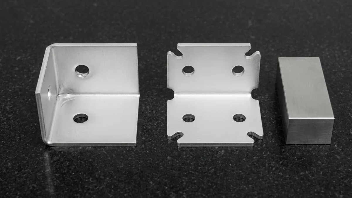
- Corner Bend Relief Notches: When bending a flange adjacent to an unbent flat sheet edge, high shear strain at the transition corner tears the metal. Tool designers must incorporate rectangular, circular, or tear-drop relief notches cut into the blank prior to bending. Relief notch width (W_relief) must equal or exceed material thickness (W ≥ t), and relief depth (D_relief) must extend beyond the tangent of the bend radius (D ≥ R_inner + t).
- Internal Fillet Radii on Cutouts: Sharp interior corners on blanked windows or notches concentrate blanking stresses, triggering micro-cracks in both the stamped part and the die block. All internal blanked corners must incorporate a minimum fillet radius R_corner ≥ 0.5t (minimum 0.50 mm).
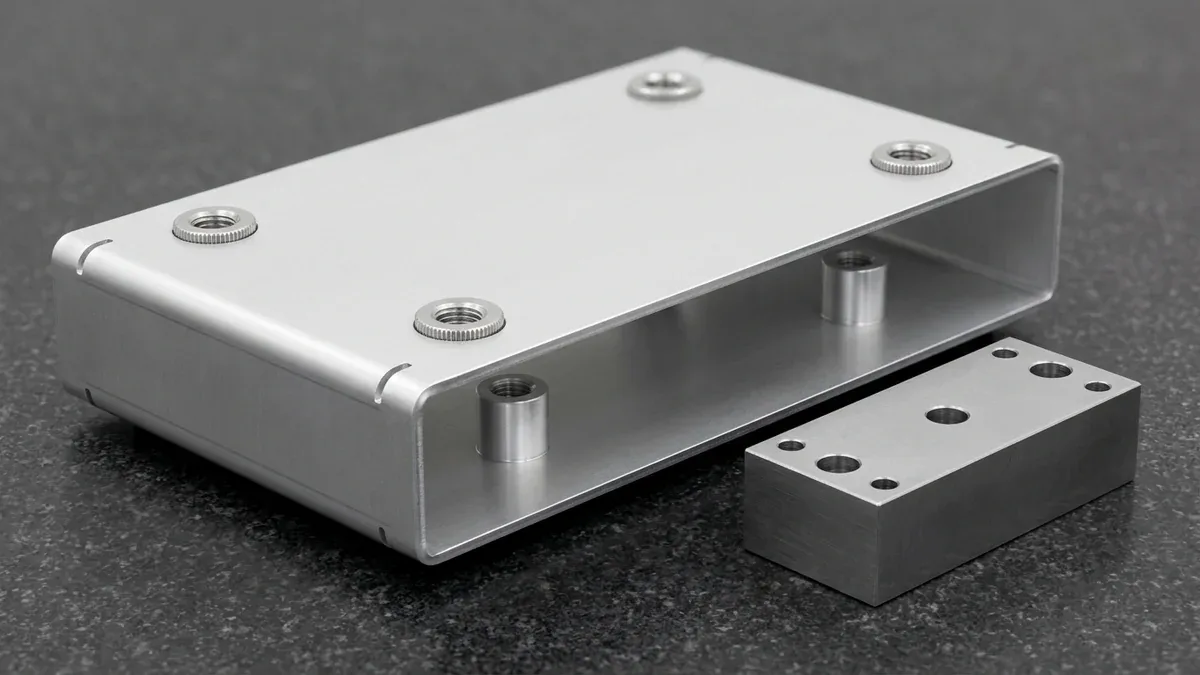
5.2 Secondary Hardware Insertion & Structural Joining
Precision stamped sheet metal brackets and enclosures frequently integrate secondary fastening hardware, joining processes, and protective finishes:
- Self-Clinching Fasteners (PEM Hardware): Precision-threaded nuts, studs, and standoffs are permanently embedded into pre-pierced sheet metal holes using hydraulic insertion machines (Haeger). When the installation punch presses the fastener into the panel under controlled force, parent sheet metal undergoes cold plastic flow into the fastener’s annular undercut groove, while a serrated clinching ring bites into the sheet. This mechanical interlock delivers exceptional torque-out resistance and push-out retention without damaging cosmetic sheet surfaces.
- Hardness Rule: The host sheet metal must be at least 20 HRB softer than the PEM fastener to permit plastic cold flow. For example, stainless steel fasteners (300 series) cannot be installed into hardened stainless sheet; specialized precipitation-hardened (A286) clinch hardware is required.
- Edge Distance Rule: Fastener centerline to sheet edge must meet the manufacturer-specified minimum (typically 1.5× fastener head diameter) to prevent bulging of the host sheet edge.
- Resistance Spot Welding (RSW, AWS D8.9): Dual water-cooled copper-alloy electrodes clamp overlapping stamped flanges under controlled pneumatic forge force while discharging high electrical current (5,000 to 18,000 Amperes). Contact resistance between the sheet surfaces melts the base metal locally, forming a cast structural weld nugget within milliseconds without filler metal or thermal warpage.Target Nugget Diameter: d_nugget ≈ 4 × √t to 5 × √t (mm)Weld pitch spacing must exceed 16× sheet thickness to prevent electrical shunting through previously formed adjacent nuggets.
- Robotic Fiber Laser & TIG Seam Welding: Used for hermetically sealed liquid-cooling enclosures or rigid automotive chassis sub-assemblies. Continuous fiber laser welding (beam spot Ø0.15 mm) delivers high-depth, low-heat-input seam welds with minimal heat-affected zones (HAZ).
6. Metrology, GD&T for Flexible Sheet Metal & Quality Assurance
Unlike rigid CNC machined billet blocks, thin-gauge sheet metal stampings are inherently non-rigid and compliant in their free state. Residual forming stresses, gravity sag, and springback create unique metrological verification challenges that require specialized inspection protocols.
6.1 Free-State vs. Restrained-State GD&T (ASME Y14.5M)
Engineering drawings for stamped sheet metal must explicitly define inspection boundary conditions:
- Free-State Condition (&circledF; Modifier): Defines geometric tolerances when the component is unconstrained, resting freely on a granite surface plate under only its own gravitational weight. Free-state callouts are critical for checking as-stamped springback and edge camber.
- Restrained Inspection Fixturing: For thin-gauge enclosures and large instrument panels, drawings specify datum clamping sequences replicating the final rigid bolted assembly. The part is clamped to a dedicated CMM checking fixture using specified clamping torques (e.g., 2.5 N·m at Datum targets A1, A2, A3) before measuring hole positions, profile tolerances, and flange squareness.
6.2 Advanced Metrology Tooling Suite
Our quality assurance laboratory combines optical, laser, and mechanical metrology platforms:
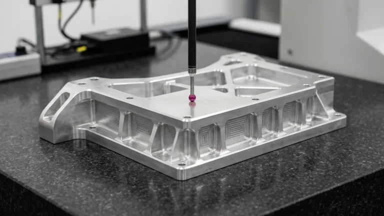
- Articulated 3D Blue Laser Scanning Arms: Portable 7-axis measuring arms equipped with non-contact blue laser line scanners capture up to 600,000 points per second across complex stamped contours. The scan data is aligned to the 3D STEP CAD model using datum alignment routines, generating comprehensive 3D color deviation heat maps with ±0.015 mm volumetric accuracy. Out-of-tolerance springback areas, twist distortions, and flange angle deviations are identified instantly across the entire surface.
- Optical Video Measuring Machines (VMM): Telecentric multi-sensor optical coordinate measuring systems inspect fine-pitch progressive terminal blanks, pierced micro-holes, and edge burrs without mechanical probe deflection. Optical edge detection achieves 0.5 μm resolution on pitch progression spacing.
- Fastener Mechanical Proof Testing: Installed self-clinching studs and nuts undergo calibrated destructive and non-destructive push-out, pull-through, and torque-out testing on digital force gauges to verify parent metal cold-flow integrity against PEM manufacturer standards.
- Environmental & Corrosion Testing: Stamped assemblies with surface finishes (Type II/III anodizing, powder coating, zinc plating) undergo ASTM B117 neutral salt spray corrosion testing (24h to 480h+) and ASTM D3359 cross-hatch adhesion tape testing to guarantee coating adhesion along sharp stamped edges.
7. Tooling Tier Selection & Production Economics Matrix
Selecting the optimal sheet metal manufacturing methodology requires balancing production volume, initial tooling investment, required dimensional tolerances, and piece-part economics:
| Tooling & Process Tier | Production Volume Range | Tooling Lead Time | Upfront Tooling Investment | Achievable Tolerances | Optimal Engineering Application |
|---|---|---|---|---|---|
| Rapid Laser + CNC Press Brake Soft Tooling | 1 to 2,500 parts | 5 to 10 business days | Minimal (Standard Laser/Brake Library Setup) | ±0.10 mm to ±0.20 mm | Functional prototypes, EVT/DVT engineering fit checks, pilot-run enclosures, frequent design changes. |
| Single-Station Stage Dies (Blank / Pierce / Form) | 2,500 to 20,000 parts | 2 to 3 weeks | Moderate (Low-Volume Hardened Tool Steel Inserts) | ±0.05 mm to ±0.10 mm | Bridge manufacturing, medium-volume brackets, pilot production validation, low part geometry complexity. |
| Multi-Station Progressive Stamping Dies | 20,000 to 1,000,000+ parts | 4 to 7 weeks | Capital Investment (Hardened DC53/D2 Progressive Tool) | ±0.025 mm to ±0.050 mm | Continuous high-speed serial manufacturing (60~450 SPM), lowest piece-part unit cost, high-precision geometry. |
| Compound Dies (Single-Stroke Blank + Pierce) | 10,000 to 500,000 parts | 3 to 5 weeks | Moderate-High (High-Precision Concentric Die) | ±0.015 mm to ±0.025 mm | Flat motor laminations, precision shim washers, high-concentricity circular brackets without strip distortion. |
| Multi-Stage Deep-Draw Transfer Dies | 15,000 to 500,000 parts | 5 to 8 weeks | High (Automated Transfer Fingers & Draw Beads) | ±0.050 mm to ±0.100 mm (High Concentricity) | Deep-drawn cylindrical motor enclosures, sensor shielding cans, deep battery housings requiring multi-draw stages. |
For austenitic stainless steels (304, 316), optimal punch-to-die cutting clearance is 10% to 14% of sheet thickness per side. Insufficient clearance accelerates tool wear, while excessive clearance causes heavy burrs and fracture taper.
K-factor defines the shift of the neutral axis toward the inner bend radius during plastic deformation. Accurately modeling K-factor in CAD flat patterns ensures exact finished flange lengths after air bending or coining.
For ductile deep-drawing steels and 5052 aluminum, the maximum blank-to-punch diameter ratio in a single draw operation is typically 1.8 to 2.2. Deeper cups require progressive multi-stage redrawing with intermediate vacuum annealing.
DC53 offers twice the Charpy fracture toughness of traditional D2 tool steel while maintaining 60 to 62 HRC hardness. This fine, uniform carbide microstructure prevents punch edge micro-chipping and cracking under high-speed cyclic impact on sharp contours.
Slug pulling is eliminated through three combined engineering methods: installing spring-loaded mechanical ejector pins inside punch faces, integrating vacuum evacuation manifolds into lower die shoes, and machining a 0.5 to 1.0 degree angular relief taper into lower die buttons.
Transform Your Sheet Metal Designs with In-House Tooling & Stamping
Whether you require 10 rapid functional sheet metal prototypes for immediate engineering fit checks or 500,000 precision stamped electrical terminals, our in-house manufacturing facility provides complete, single-source sheet metal fabrication under one roof. Our precision stamping center integrates high-precision fiber laser cutting, multi-axis CNC press brakes, progressive stamping presses up to 500 tons, automated PEM fastener insertion, and 3D laser scanning metrology.
Upload your 3D CAD models and 2D engineering drawings to receive a comprehensive Design for Manufacturability (DFM) assessment, K-factor bend analysis, strip progression review, and an itemized production quotation within 24 hours.