

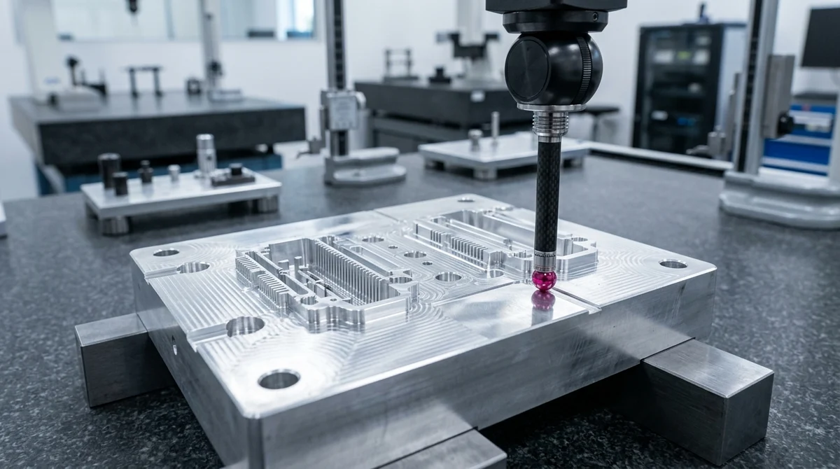
In agile hardware development and on-demand manufacturing, committing tens of thousands of dollars and waiting 12 to 16 weeks for production steel tooling represents an unviable project risk. Engineering teams bringing consumer electronics, automotive brackets, industrial enclosures, and medical diagnostics to market require production-grade injection molded parts in days, not months. The decisive solution bridging functional 3D printing and high-volume mass production is an aluminum injection mold (rapid tooling).
⏱️ Estimated Reading Time: ~7 mins | Target Audience: Tooling Engineers, Mechanical Designers, R&D Program Managers & Sourcing Specialists
Written by: AS Prototypes Precision Tooling Engineering Team | Technically Reviewed by: Senior Mold Design & Injection Molding Specialist (14+ Years Shop-Floor Experience)
- High-Performance Tooling Alloys: High-purity structural 7075-T6, Alumold 500, and QC-10 mold plates engineered for uniform density and minimal internal porosity.
- Precision Tooling Tolerances: Critical mold cavity features held to ±0.010 mm (±0.0004″) with shut-off land planarity within 0.008 mm (0.0003″).
- Thermal Efficiency Advantage: Thermal conductivity of 130 to 160 W/(m·K) [75 to 92 BTU/(hr·ft·°F)] reduces cooling cycles by 20% to 35% compared to P20 mold steel.
- Bridge Production Turnaround: Functional T1 molded samples delivered within 18 to 25 business days, including DFM engineering review within 24 hours.
- Core Focus & DFM Scope: Actionable shop-floor engineering guidelines for aluminum injection mold, covering material selection, geometric tolerancing, and defect prevention.
- Dimensional Tolerance Baseline: General molded/cast features hold ISO 2768-mK or ±0.05 to ±0.10 mm (±0.002″ to ±0.004″); critical post-machined datum bores achieve ±0.010 mm (±0.0004″).
- Tooling & Surface Integrity: Cavity surfaces finished from SPI A-2 mirror polish (Ra 0.05 µm / 2 µin) to VDI 3400 spark-eroded textures with mandatory 1.0°–2.5° draft angle compensation.
- Metrology & Flow Validation: Pre-tooling DFM and rheological fill simulation paired with Zeiss CMM first-article inspection (FAI) and wall-thickness ultrasonic/section verification.
- Ex-Factory Turnaround: 7 to 12 business days for vacuum cast/urethane bridge batches; 18 to 35 business days for rapid aluminum/P20/H13 tooling and T1 sample delivery (excluding 3–5 days air transit).
Executive Comparison Matrix: Tooling Materials
Selecting an optimal mold tooling strategy requires evaluating upfront capital expenditure, part volume demands, resin abrasiveness, and tolerance capability. At AS Prototypes, our machine shop manufactures both bridge aluminum tooling and hardened production molds to align with specific project volumes.
| Engineering Metric | 7075-T6 / QC-10 Aluminum | Pre-Hardened P20 / NAK80 Steel | Hardened H13 / S136 Tool Steel | 3D-Printed Mold Inserts (SLA/DMLS) |
|---|---|---|---|---|
| T1 Lead Time | 18 to 25 business days | 4 to 6 weeks | 8 to 14 weeks | 4 to 8 business days |
| Relative Tooling CapEx | 1.0x (Baseline) | 1.7x to 2.3x | 2.8x to 4.5x | 0.6x to 0.9x |
| Thermal Conductivity | 130 – 160 W/(m·K) (Ultra-High) | 29 – 32 W/(m·K) (Standard) | 24 – 28 W/(m·K) (Low) | 0.2 W/(m·K) (Resin) / 15 (DMLS) |
| Cycle Time Reduction | 20% to 35% faster cooling | Baseline reference | Baseline reference | 200% to 400% slower cycle |
| Mold Cavity Tolerance | ±0.010 mm (±0.0004″) | ±0.008 mm (±0.0003″) | ±0.005 mm (±0.0002″) | ±0.050 mm (±0.0020″) |
| Rated Shot Life | 10,000 to 100,000+ shots | 250,000 to 500,000 shots | 1,000,000+ shots | 50 to 200 shots |
| Surface Texture Grade | SPI-A2 (Ra 0.05 μm), VDI 24-33 | SPI-A1 (Optical Mirror), Mold-Tech | SPI-A1 (Diamond Mirror), Texturing | Stepped / Layered; Matte only |
| Engineering Change (ECO) | Rapid (Direct remill / insert) | Moderate (Laser weld / remachine) | Difficult (Anneal or grind/EDM) | Impossible (Reprint required) |
| Recommended Application | Bridge tooling, pilot runs (1k-50k) | Medium production (50k-250k) | Mass production (>250k units) | Functional validation (10-50 pcs) |
The Physics of Heat Dissipation: Why Aluminum Outperforms Steel in Mold Cooling
Aluminum mold tooling dissipates thermal energy at a rate approximately four to five times faster than standard tool steels, directly shortening injection cycle times by 20% to 35%. While novice designers occasionally assume aluminum tooling produces sluggish cycle times, heat transfer thermodynamics demonstrates that aluminum extracts latent heat from molten resins with unmatched efficiency.
In standard thermoplastic injection molding, the cooling phase accounts for 60% to 75% of the total cycle time. Solidification velocity depends on the thermal conductivity and thermal diffusivity of the mold cavity material:
- 7075-T6 Aircraft Aluminum: Thermal conductivity k ≈ 130 to 160 W/(m·K) [75 to 92 BTU/(hr·ft·°F)]
- Pre-Hardened P20 Mold Steel: Thermal conductivity k ≈ 29 to 32 W/(m·K) [17 to 18.5 BTU/(hr·ft·°F)]
- Hardened H13 Tool Steel: Thermal conductivity k ≈ 24 to 28 W/(m·K) [14 to 16 BTU/(hr·ft·°F)]
Thermal diffusivity (κ = k / (ρ · Cp)) dictates how rapidly heat propagates through a solid mass. Aluminum exhibits a thermal diffusivity of approximately 48 to 58 mm²/s, compared to just 8.5 mm²/s for P20 steel. This roughly six-fold diffusion advantage allows aluminum tools to absorb heat rapidly from thick nominal walls and deep bosses.
Homogeneous heat extraction minimizes localized thermal hot spots across core and cavity geometries. Consequently, parts molded in aluminum tooling experience lower residual molded-in stress, substantially reducing post-ejection warpage and sink mark severity in semicrystalline resins such as polypropylene (PP) and polyamides (PA66).
Tool Machinability & Rapid Turnaround: High-Speed Cavity Milling
Structural aluminum alloys achieve metal removal rates (MRR) three to four times higher than pre-hardened tool steels, drastically reducing machining hours and cutter wear. In our Shenzhen tooling center, high-speed multi-axis vertical machining centers (VMCs) cut complex parting lines, core pins, and deep pockets directly from solid billet without costly furnace heat treatment.
During cavity finishing, high-speed multi-axis machining centers run small-diameter carbide ball-nose end mills at spindle speeds of 20,000 to 24,000 RPM. This direct-to-cavity milling approach produces an ultra-fine as-machined surface finish down to Ra 0.4 μm (16 μin) and holds tight parting line tolerances within ±0.010 mm (±0.0004″) (as shown in the high-speed CNC milling setup below).
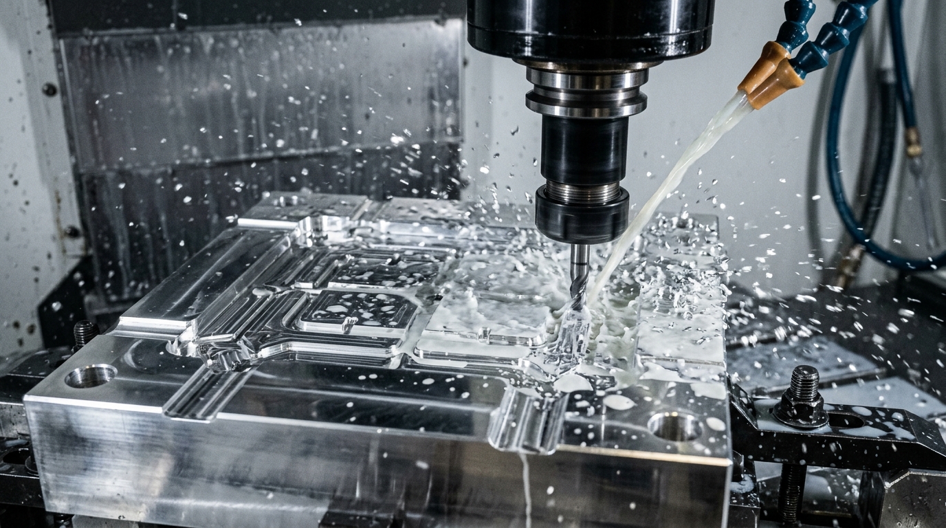
Key toolroom advantages of aluminum rapid tooling include:
- Reduced Manual Bench Polishing: Because direct-to-cavity high-speed milling achieves Ra 0.4 μm (16 μin) directly off the machine, toolmakers eliminate dozens of manual bench-stoning hours to attain smooth SPI-B1 and SPI-A2 finishes.
- Efficient Sinker EDM Performance: For deep, narrow ribs where electrical discharge machining (EDM) is required, aluminum sparks up to five times faster than P20, reducing graphite electrode consumption and discharge cycles as detailed in our precision mold making and EDM toolroom process guide.
- Agile Engineering Change Orders (ECOs): If physical fitment testing necessitates wall thickness or boss modifications, aluminum tooling can be modified, re-machined, welded, or fitted with inserts within 3 to 5 business days without annealing furnace cycles.
For custom components requiring validated bridge tooling or scalable pilot production, integrating custom rapid tooling and injection molding enables functional hardware delivery to market months ahead of traditional steel toolmakers.
Engineering Calculation: Thermal Expansion & Shut-Off Preload
Thermal expansion differential between aluminum mold inserts and steel mold bases requires precise geometric compensation in CAM programming to prevent parting line flash or core binding. Aluminum alloys expand at approximately double the rate of carbon tool steels under elevated molding temperatures.
Consider a 200 mm (7.874″) mold core insert operating at a steady-state mold temperature of 60°C (140°F) from an ambient toolroom setup temperature of 20°C (68°F), creating a temperature differential ΔT = 40°C (72°F). The linear thermal expansion is calculated using the standard physical formula:
Where:
• L = 200 mm (Insert length dimension)
• ΔT = 40°C (Temperature rise from 20°C to 60°C)
• 7075-T6 Aluminum Expansion: αAl ≈ 23.4 × 10⁻⁶ / K
ΔLAl = 23.4 × 10⁻⁶ × 200 × 40 = 0.187 mm (0.0074″)
• P20 Mold Steel Pocket Expansion: αSteel ≈ 12.0 × 10⁻⁶ / K
ΔLSteel = 12.0 × 10⁻⁶ × 200 × 40 = 0.096 mm (0.0038″)
• Net Differential Thermal Expansion:
Δ = ΔLAl – ΔLSteel = 0.091 mm (0.0036″)
If toolmakers machine aluminum core inserts to line-to-line dimensions within a steel mold frame, thermal expansion under continuous molding cycles causes core interference, binding sliding mechanisms and inducing excessive shut-off land stress. In our shop floor practice, our engineers incorporate a calibrated 0.050 mm (0.0020″) per-side pocket perimeter clearance gap (0.100 mm total, above the 0.091 mm net growth) and a 0.015 mm (0.0006″) kiss-off land pre-load to maintain flash-free shut-offs throughout thermal cycling.
Tool Life Longevity & Surface Hardening Strategies (ENP & Hard Anodize)
While untreated 7075-T6 aluminum possesses a core surface hardness of approximately 150 HB (compared to 300 to 320 HB for pre-hardened P20 steel), targeted metallurgical surface engineering extends aluminum mold longevity beyond 100,000 shots. By shielding high-wear areas, our tooling engineers ensure repeatable dimensional stability across demanding production runs.
- Electroless Nickel Plating (ENP): Applying a uniform 25 μm (0.0010″) electroless nickel deposit elevates surface micro-hardness to 50-52 HRC. This barrier layer prevents corrosive chemical attack from off-gassing flame-retardant resins (e.g., UL94-V0 PC/ABS) and shields gate runners from abrasive scouring.
- MIL-A-8625 Type III Hardcoat Anodizing: A 50 μm (0.0020″) hard anodized layer impregnated with PTFE delivers a surface hardness of approximately 400 to 600 HV (about 41 to 49 HRC). This ultra-hard ceramic conversion coating dramatically reduces sliding friction on ejector pin holes, guide bushings, and parting line shut-offs.
- Hybrid Hardened Steel Inserts: For mold features subject to severe mechanical abrasion—such as sprues, sub-gates, sliding cam faces, and delicate lifter blades—we integrate hardened H13 or O1 steel inserts directly into the aluminum base, isolating sliding friction from the softer aluminum matrix.
Toolroom Quality Metrology: CMM Parting Line Verification
Parting line flash occurs when mold halves deflect under high injection packing pressure or when shut-off land planar tolerances exceed 0.012 mm (0.0005″). Because aluminum possesses an elastic modulus of approximately 71 GPa (compared to 205 GPa for steel), shut-off lands require stringent geometric dimensioning and metrology verification.
To minimize flash formation under clamping forces exceeding 100 tons, mold shut-off lands and alignment guide pockets undergo rigorous dimensional verification. Toolmakers inspect parting surface planarity within 0.008 mm (0.0003″) using high-precision tactile continuous scanning probes in a temperature-stabilized metrology lab (as demonstrated during coordinate measuring machine inspection below).
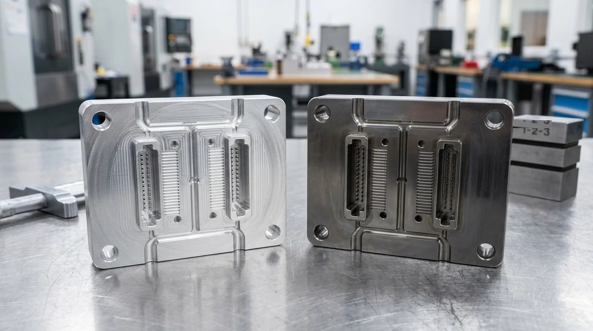
Every rapid aluminum mold fabricated in our facility undergoes standardized quality inspection protocols:
- Continuous Scanning CMM Verification: Inspecting cavity depth, core concentricity, and shut-off land flatness across Datum A within ±0.008 mm (±0.0003″) before tool assembly.
- 2.5D Optical Vision & Stylus Surface Profilometry: Mapping compound 3D freeform parting contours to confirm seamless kiss-off contact along contoured split lines.
- Scientific Molding First Article Inspection (FAI): T1 molded trial components undergo full dimensional verification against 2D GD&T drawings, ensuring process capability index Cpk ≥ 1.33 across all critical dimensions.
Shop-Floor Troubleshooting: Why Parting Line Flash Occurs & Fixes
Parting line flash on aluminum injection tooling primarily stems from hydraulic clamping deflection, uncompensated thermal expansion, or excessive peak injection packing pressures exceeding the yield boundary of aluminum shut-off lands. Low-viscosity resins such as unreinforced PA66 or POM exacerbate flash if shut-off clearances widen beyond 0.015 mm (0.0006″).
Our tooling engineers utilize the following diagnostic protocol to resolve parting line flash in rapid tooling:
Diagnostic Case: Parting Line Flash on Low-Viscosity Engineering Resins
- Symptom: Micro-flash exceeding 0.030 mm (0.0012″) forming along the primary mold split line during the packing and holding phase of PA66 molding.
- Root Cause Analysis: Machine clamp tonnage was concentrated solely on the aluminum mold core. Under 850 bar cavity pressure, localized elastic compression of the aluminum face opened a 0.025 mm gap across peripheral shut-off lands.
- Shop-Floor Corrective Action:
- Kiss-Off Crown Geometry: Machined a 0.018 mm (0.0007″) stepped pre-load kiss-off land along the cavity perimeter to create targeted contact pressure upon mold closure.
- Steel Stop Blocks: Installed four hardened H13 tool-steel stop pillars on the mold shoe frame to absorb machine clamping force, preventing aluminum face crushing.
- Scientific Molding Decoupled Pressure: Adjusted the switchover point to transfer from fill to pack at 95% volumetric fill, reducing cavity peak pressure spikes by 22%.
Objective Engineering Trade-Offs: When NOT to Choose Aluminum Tooling
Aluminum injection molds provide unmatched speed and thermal economy for low-to-mid volume programs, but physical metallurgy dictates distinct operational limitations. Sourcing engineers should avoid aluminum tooling in the following scenarios:
- High-Volume Long-Run Production (>100,000 Cycles): When production forecasts demand hundreds of thousands or millions of parts, pre-hardened P20 or fully hardened H13 tool steel provides superior wear resistance and lower long-term per-part amortized tooling costs.
- Highly Abrasive Glass-Filled Resins in High Volumes: While resins with 15% to 30% glass fibers (such as PA66-GF30 or PBT-GF20) run successfully in nickel-plated aluminum molds for 5,000 to 20,000 shots, programs targeting 50,000+ parts in abrasive materials require hardened steel tool cavities (50+ HRC) to resist severe gate washing.
- Class-A Diamond Optical Mirror Finishes (SPI A-1): Optical lenses and clear light pipes requiring SPI A-1 diamond mirror polish demand hardened stainless mold steels (such as S136 or 420 SS) to prevent micro-scratching during mold maintenance. Aluminum reliably supports SPI A-2 high-gloss finishes.
- Extreme Clamp Pressures & High Tonnage Thin-Wall Molding: Ultra-thin wall parts (≤0.6 mm) requiring ultra-high injection pressures (>1,600 bar) can induce elastic core deflection in aluminum, leading to dimensional variation across multi-cavity layouts.
The Verdict: Tooling Material Selection Framework
Selecting the optimal mold material depends on production volume, resin characteristics, design maturity, and project timelines. Follow this shop-tested decision framework to determine your tooling path:
- Choose 7075-T6 Aluminum Rapid Tooling When: Total production volume ranges from 500 to 50,000 parts, rapid market delivery is essential (T1 parts in 18 to 25 business days), engineering changes (ECOs) are anticipated, or fast cooling cycle times are required to prevent part warpage.
- Choose Plated Aluminum with Steel Inserts When: Running moderately abrasive resins (15% to 30% glass-fill) or flame-retardant materials for bridge production batches between 5,000 and 20,000 parts before investing in hardened steel tooling.
- Choose Pre-Hardened P20 / NAK80 Steel When: Annual production volumes range from 50,000 to 250,000 units, the part design is completely locked, and standard cycle time economics are acceptable.
- Choose Hardened H13 / S136 Steel Production Tooling When: Manufacturing high-volume mass production (>250,000 to 1,000,000+ units), molding aggressive engineering resins, or producing optical-grade lenses requiring SPI A-1 diamond mirror finishes.
Frequently Asked Questions (Engineering FAQ)
Yes, aluminum molds readily process glass-filled resins (such as 15% to 30% glass-filled PA66, PBT, or PC) for prototype and bridge runs of 5,000 to 20,000 parts. Applying Electroless Nickel Plating (ENP) or installing hardened tool-steel gate inserts protects high-velocity resin flow areas against abrasive wear.
Thermoplastic parts cool 20% to 35% faster in 7075-T6 aluminum molds than in standard P20 tool steel. Because aluminum conducts heat at 130 to 160 W/(m·K) compared to 29 W/(m·K) for P20 steel, cooling time is substantially compressed, yielding shorter overall cycle times and reduced part warpage.
We recommend a minimum draft angle of 1.0° to 1.5° per side for smooth polished surfaces (SPI-B1/B2) and 2.0° to 3.0° per side for textured finishes (VDI 24-30). Proper draft angles ensure clean part ejection and prevent micro-galling on aluminum cavity sidewalls.
Yes. Aluminum tooling is exceptionally adaptable to engineering change orders. Because the alloy does not undergo brittle furnace hardening, toolmakers can quickly re-mill cavity features, machine insert pockets, or weld aluminum within 3 to 5 business days without requiring annealing cycles.
Fast-Track Your Injection Molding Program with Precision Rapid Tooling
Bridge the gap between functional prototyping and high-volume production. Upload your 3D CAD models (STEP/IGES) for a comprehensive DFM review, mold flow analysis, and engineering quote within 24 hours.
Request a Rapid Tooling Quote






