

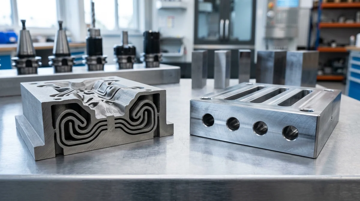
Since the commercial maturation of additive manufacturing (AM), an enduring question has circulated across hardware startups, OEM engineering departments, and procurement forums: Will 3D printing replace traditional tooling and injection molding? Sensationalist headlines frequently declare the imminent demise of heavy machine tools, electrical discharge machining (EDM), and multi-ton steel molds in favor of direct digital fabrication from 3D CAD files. However, on the factory floor, fundamental manufacturing physics, thermodynamics, and mass production economics tell a decisively different story.
Rather than locking additive manufacturing and conventional mold making into an adversarial zero-sum conflict, modern precision production has entered an era of symbiotic co-existence and hybrid tooling. By integrating Direct Metal Laser Sintering (DMLS) 3D printing with high-speed 3/4-axis CNC milling, rapid aluminum tooling, and automated injection molding, engineering teams can eliminate thermal hot spots, compress production cycle times, and navigate the unit-cost crossover curve with maximum capital efficiency.
- Core Focus & DFM Scope: Actionable shop-floor engineering guidelines for will 3D printing replace tooling, covering material selection, geometric tolerancing, and defect prevention.
- Dimensional Tolerance Baseline: General molded/cast features hold ISO 2768-mK or ±0.05 to ±0.10 mm (±0.002″ to ±0.004″); critical post-machined datum bores achieve ±0.010 mm (±0.0004″).
- Tooling & Surface Integrity: Cavity surfaces finished from SPI A-2 mirror polish (Ra 0.05 µm / 2 µin) to VDI 3400 spark-eroded textures with mandatory 1.0°–2.5° draft angle compensation.
- Metrology & Flow Validation: Pre-tooling DFM and rheological fill simulation paired with Zeiss CMM first-article inspection (FAI) and wall-thickness ultrasonic/section verification.
- Ex-Factory Turnaround: 7 to 12 business days for vacuum cast/urethane bridge batches; 18 to 35 business days for rapid aluminum/P20/H13 tooling and T1 sample delivery (excluding 3–5 days air transit).
Executive Summary & Engineering Takeaways (BLUF)
- The Volumetric Throughput Gap: Injection molding delivers finished parts in 10 to 30 seconds per shot, discharging thousands of parts per hour on multi-cavity production presses (volumetric output >36,000 cm³/hr). Additive manufacturing builds layer-by-layer (typical build rates of 15 to 40 cm³/hr per laser), with a single 14 to 36 hour build yielding only about 200 to 1,400 cm³ of parts (versus more than 36,000 cm³ per hour of molding).
- Symbiosis via Hybrid Tooling: 3D printing is not eliminating tooling; it is revolutionizing mold performance through DMLS 1.2709 maraging steel conformal cooling inserts, reducing molding cycle times by 25% to 45% and reducing differential thermal shrinkage.
- Economic Crossover Reality: Direct 3D printing provides unbeatable economic agility for 1 to 500 units due to zero tooling non-recurring engineering (NRE). Rapid aluminum tooling (7075-T6) dominates the 500 to 10,000 unit bridge production window. Hardened production steel molds (P20, H13, S136) govern 10,000 to millions of units with lowest piece-part conversion costs.
- Material Isotropy & Resin Diversity: Injection molding processes over 85,000 commercial thermoplastics, delivering near-isotropic mechanical properties (unfilled grades). Polymer 3D printing remains constrained to approximately 50 commercial grades and exhibits anisotropic Z-axis interlayer shear strength reductions of 15% to 35%.
- Secondary Machining Imperative: As-printed metal and polymer AM components exhibit surface roughness of Ra 4.0 to 10.0 μm. High-speed 3/4-axis CNC milling, wire EDM, and diamond hand-polishing remain essential to achieve mold cavity tolerances of ±0.010 mm and SPI-A1/A2 optical surface finishes.
Authored and reviewed by the AS Prototypes Tooling & Additive Manufacturing Engineering Group.
Article Engineering Navigation
- 1. The Industrial Displacement Myth vs. Manufacturing Reality
- 2. Thermodynamics & Volumetric Deposition: The Cycle Time Chasm
- 3. DMLS Conformal Cooling Inserts: Additive Engineering Inside Traditional Tooling
- 4. The Economic Breakeven Curve & Cost Crossover Dynamics
- 5. Material Isotropy, Surface Finish & Structural Integrity
- 6. Shop-Floor Reality: CNC Milling Workhorses & Metrology Validation
- 7. Strategic Engineering Decision Framework: When to Print vs. When to Tool
- 8. Technical Engineering FAQ
1. The Industrial Displacement Myth vs. Manufacturing Reality
The prediction that 3D printing would render the global tooling industry obsolete gained traction during the initial expansion of industrial stereolithography (SLA), selective laser sintering (SLS), and fused deposition modeling (FDM). Technologists envisioned a digital future where physical mold bases, EDM copper electrodes, and multi-axis CNC machines were superseded by banks of additive printers generating end-use parts on demand directly from CAD geometry.
This narrative misinterprets the fundamental nature of mass production. Tooling exists not as an arbitrary cost burden, but as a highly engineered thermo-mechanical heat exchanger and pressure vessel designed to enforce geometry, surface finish, and metallurgical consistency with sub-second repeatability. While additive manufacturing has established itself as an indispensable method for functional prototyping, customized low-volume production, and high-complexity aerospace topologies, it operates under thermodynamic boundaries that prevent it from displacing mass-production molds.
In contemporary manufacturing ecosystems, the relationship between additive manufacturing and conventional tooling is collaborative rather than substitutive. Additive processes accelerate mold prototyping, generate sacrificial tooling for composite layup, and create highly intricate mold components that cannot be produced by subtractive methods. The emergence of hybrid tooling—where metal 3D printed inserts are integrated into conventional CNC-machined mold plates—exemplifies how additive manufacturing enhances, rather than eliminates, traditional injection molding.
2. Thermodynamics & Volumetric Deposition: The Cycle Time Chasm
The insurmountable physical barrier preventing 3D printing from replacing conventional injection molding in volume production lies in volumetric deposition physics and thermal diffusion rates. Understanding this distinction requires examining the heat transfer and material delivery mechanisms of both manufacturing methodologies.
In high-pressure thermoplastic injection molding, molten polymer at 200°C to 340°C is injected into a chilled metal tool cavity under hydraulic or servo-electric pressures ranging from 500 to 1,600 bar. Once the cavity is packed, heat rapidly transfers into the mold steel through conduction, described by the one-dimensional unsteady-state heat conduction equation:
tcool ≈ (hwall2 / (π2 · α)) · ln[(4 / π) · ((Tmelt – Tmold) / (Teject – Tmold))]
where hwall represents the nominal part wall thickness, α is the polymer thermal diffusivity (α = k / (ρ · Cp)), Tmelt is the melt temperature, Tmold is the cooling circuit temperature, and Teject is the ejection temperature. Because the mold steel or aluminum exhibits thermal conductivities of 29 to 160 W/(m·K), the plastic skin solidifies within seconds. In a typical multi-cavity injection mold (e.g., 16 to 32 cavities), a single press discharges dozens of finished, fully consolidated components every 12 to 25 seconds. The resulting volumetric throughput easily exceeds 36,000 to 120,000 cm³ per hour.
Conversely, additive manufacturing builds parts sequentially through micro-scale localized thermal transformations. Whether using a CO2 laser melting fine nylon powder (SLS), an infrared fusing lamp with liquid detailing agents (MJF), or an ytterbium fiber laser melting metal powder (DMLS), the volumetric build rate is governed by the laser scan speed, recoater blade sweep duration, and powder melting dynamics:
Volumetric Build Rate (QAM) = Layer Thickness (t) · Hatch Spacing (h) · Scan Speed (v)
In practical industrial operations, a state-of-the-art DMLS machine operating a 400W laser achieves build rates between 15 and 35 cm³ per hour. Industrial SLS polymer systems operate between 500 and 1,500 cm³ per hour across the entire active build envelope. Fabricating an order of 10,000 structural brackets measuring 50 mm × 30 mm × 20 mm requires several weeks of non-stop printing across multiple high-capital AM platforms, accompanied by powder recycling, sifting, and manual de-powdering. In contrast, an automated 4-cavity injection mold produces that entire volume in less than 35 machine hours.
3. DMLS Conformal Cooling Inserts: Additive Engineering Inside Traditional Tooling
Far from disrupting mold shops, additive manufacturing has sparked one of the greatest leaps in tooling efficiency through conformal cooling channels. In conventional mold making, cooling lines are drilled using gun drills and multi-axis deep-hole drilling centers. Because CNC drill bits must travel along straight Cartesian trajectories, they cannot follow complex curved part topographies, resulting in uneven cooling distances across deep ribs, cores, and boss geometries.
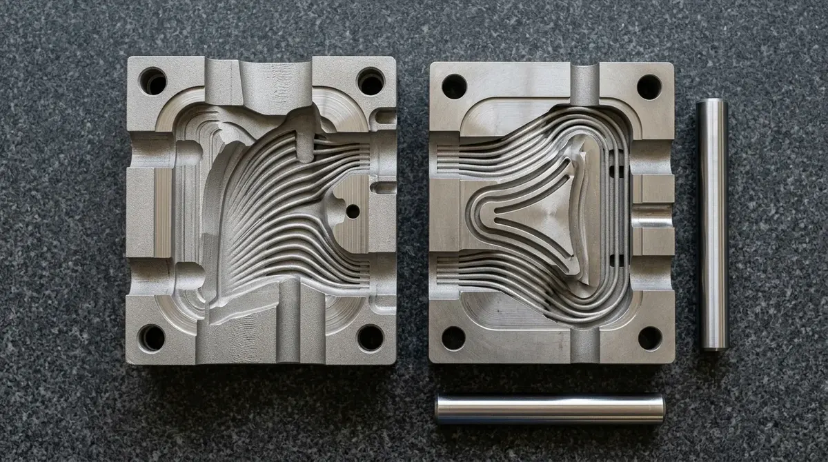
To overcome straight-line cooling constraints, precision toolmakers utilize Direct Metal Laser Sintering (DMLS) to print mold inserts in 1.2709 Maraging Steel (MS1) or Corrax stainless steel. Additive manufacturing enables fluid channels to sweep along freeform 3D curves, maintaining an exact, equidistant offset (typically 2.0 to 3.5 mm) from the mold cavity surface across all part contours.
The fluid dynamics inside these printed conformal channels are engineered to maintain high turbulence, preventing laminar boundary layer insulation. By ensuring the Reynolds number exceeds 10,000, heat transfer from the steel to the circulating water coolant is maximized:
Re = (ρ · v · DH) / μ ≥ 10,000
where ρ is coolant fluid density, v is flow velocity, DH is hydraulic channel diameter, and μ is dynamic viscosity. Conformal cooling channels deliver four transformative engineering advantages on the production floor:
- Cycle Time Compression: Cooling phase durations decrease by 25% to 45%, delivering massive machine-hour cost savings across high-tonnage automated injection molding cells.
- Elimination of Differential Shrinkage: Thermal hot spots in thick ribs or deep bosses are actively cooled at the same rate as thin nominal walls, reducing part warpage, bow distortion, and surface sink marks.
- Extended Tool Component Life: Eliminating severe thermal gradients across tool steel inserts mitigates cyclic thermal fatigue and micro-cracking, dramatically extending tool maintenance intervals.
- Seamless Hybrid Integration: Printed maraging steel inserts undergo stress-relief vacuum annealing, precipitation age hardening at 490°C for 6 hours (reaching 50 to 54 HRC), followed by high-speed CNC milling and precision wire EDM to achieve mirror-grade SPI-A2 mold surface finishes.
4. The Economic Breakeven Curve & Cost Crossover Dynamics
Every plastic and metal component adheres to a total cost of ownership (TCO) crossover curve determined by upfront non-recurring engineering (NRE) tooling investment balanced against incremental piece-part manufacturing costs. Visualizing and calculating this crossover point is essential for determining whether to print parts directly, deploy rapid aluminum tooling, or build production steel molds.
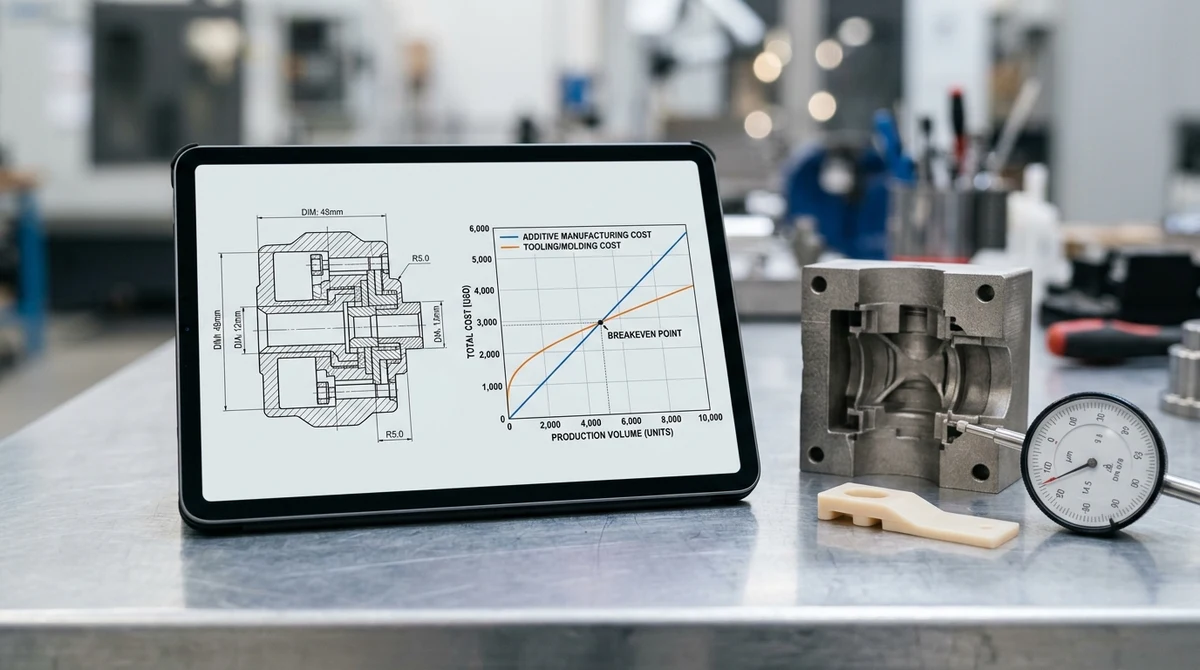
The total unit cost as a function of production volume V is expressed through the fundamental manufacturing economic formulations:
CAM(V) = Csetup + Craw_material + (tbuild · Rmachine) / Nbatch + Cpost_finishing
CTooling(V) = (NREmold / V) + Cresin_pellet + (tcycle · Rpress) / Ncavities + CQC
In direct additive manufacturing, the cost per unit remains relatively flat across production volumes because each part requires a nearly identical consumption of laser run-time, electrical power, and premium powder feedstock. In injection molding, the upfront tooling NRE is divided across the total production volume V, generating a steep hyperbolic decay in per-part cost. Once the tooling investment is amortized, the variable cost per shot consists primarily of raw thermoplastic resin pellets and fractions of press machine-hours.
Based on rigorous shop-floor data and DFM assessments, the economic sweet spots categorize into three distinct volume tiers:
- Prototyping & Agile Low Volume (1 to 500 units): Direct 3D Printing Wins. With zero mold NRE, immediate CAD-to-machine setup, and total freedom for revision changes, processes like SLS, MJF, SLA, and DMLS represent the most cost-effective path for concept models, ergonomic trials, and proof-of-concept testing.
- Bridge Production & On-Demand Batches (500 to 10,000 units): Rapid Aluminum Tooling Dominates. Machined from high-strength 7075-T651 aluminum plates or modular Master Unit Die (MUD) inserts, aluminum bridge tooling keeps tooling investment and design-change iteration cost low, with first shots typically within 18 to 35 business days. Tooling NRE is amortized across several thousand units, granting access to genuine commercial-grade polymers at highly economical piece-part rates.
- High-Volume & Mass Manufacturing (>10,000 to Millions of Units): Production Steel Tooling Rules. Dedicated multi-cavity molds fabricated from hardened tool steels (P20, NAK80, H13, S136) amortize initial capital expenditure to a small fraction of per-part cost, operating automated robotic pick-and-place demolding around the clock.
5. Material Isotropy, Surface Finish & Structural Integrity
Beyond cycle times and unit costs, mechanical performance criteria often dictate the choice between 3D printing and conventional tooling. Two critical material characteristics distinguish molded parts from additively produced counterparts: structural isotropy and surface morphology.
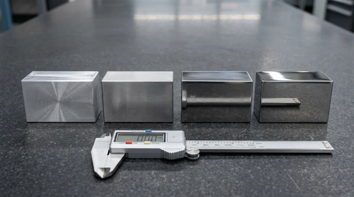
Because additive manufacturing deposits material layer upon layer, the resulting component exhibits anisotropic or orthotropic mechanical properties. In SLS or FDM parts, the interlaminar shear strength along the vertical Z-axis is typically 15% to 35% lower than the tensile strength in the horizontal X-Y plane. Even in dense metal 3D printing (DMLS), micro-voids and columnar grain structures require hot isostatic pressing (HIP) and vacuum stress relief to approach the fatigue performance of wrought or forged alloys.
Conversely, high-pressure injection molding forces molten polymer through runners and gates under extreme shear, followed by intensive holding pressure. While molecular chains orient along the melt flow front (fountain flow), the core material achieves complete polymer chain entanglements, creating a largely isotropic structure with very low internal porosity. Furthermore, injection molding supports over 85,000 commercial thermoplastics, including highly specialized compounds with 10% to 50% carbon or glass fiber reinforcement, PTFE internal lubricants, UL94 V-0 flame retardants, and medical USP Class VI biocompatibility.
Surface quality presents an equally significant contrast. As-sintered polymer AM parts exhibit a grainy, porous surface with roughness values of Ra 4.0 to 10.0 μm, requiring labor-intensive secondary post-processing such as chemical vapor smoothing or ceramic media blasting. Molded components replicate the exact finish of the cavity steel on every single cycle, whether that requires an optical diamond mirror finish (SPI-A1 / SPI-A2, Ra < 0.05 μm) or precise molded-in texture standards (VDI 3400 spark erosion, Mold-Tech graining).
6. Shop-Floor Reality: CNC Milling Workhorses & Metrology Validation
Modern precision mold manufacturing relies heavily on state-of-the-art subtractive machining centers. In a production tooling environment, high-speed 3-axis and 4-axis vertical machining centers (VMCs) carry out 75% to 85%+ of overall machining capacity. They machine mold bases, water cooling manifolds, ejector pin retainer plates, core/cavity pockets, and slide mechanisms with remarkable speed and economic efficiency.
Simultaneous 5-axis CNC machining centers are deployed strategically for complex 3D parting lines, deep pocket contours, high-aspect-ratio graphite electrodes, and post-machining of printed DMLS inserts. By maintaining optimal tool contact angles and short, rigid tool overhangs, 5-axis milling reduces chatter marks and achieves superior surface integrity on contoured mold shut-offs.
Dimensional verification is performed under climate-controlled conditions (20°C ± 0.5°C) using high-precision tactile coordinate measuring machines (Zeiss CMM) and non-contact structured blue light optical scanners. Mold bases adhere to general machining standards (ISO 2768-mK), while critical shut-off lands, slide alignment gibs, and interlocking taper locks are held to tight tolerances of ±0.010 mm to ±0.020 mm. Precision wire EDM processes fine ejector pin holes and insert pockets down to ±0.005 mm.
| Engineering Parameter | Direct 3D Printing (SLS/MJF/DMLS) | Rapid Aluminum Tooling (7075-T6) | Hardened Steel Molds (P20/H13/S136) | Hybrid DMLS Conformal Tooling |
|---|---|---|---|---|
| Tooling Setup Investment (NRE) | Near-Zero (Direct Digital Setup) | Low to Moderate (Rapid MUD Base) | High (Dedicated Production Mold) | Moderate to High (DMLS Inserts + Steel Plates) |
| Lead Time to First Article | 4 to 8 business days | 18 to 35 business days | 18 to 35 business days | 18 to 35 business days |
| Unit Part Cost Profile | Flat (Linear material/machine time) | Sharp volume drop (Economies of scale) | Lowest overall unit cost | Lowest unit cost + 30% press cycle savings |
| Production Cycle Time | 14 to 36 hours per full build cake | 15 to 35 seconds per shot | 12 to 25 seconds per shot | 8 to 16 seconds per shot (Fastest) |
| Structural Isotropy & Voids | Anisotropic Z-axis (15-35% lower); micro-voids | Largely isotropic; low void content | Largely isotropic; low void content | Largely isotropic; low void content |
| Resin Selection Scope | ~50 specialized powders/photopolymers | 85,000+ commercial resins (PP, ABS, PC, POM) | Full resin catalog + high glass-fill grades | Full resin catalog + high glass-fill grades |
| As-Produced Surface Finish | Porous/Granular (Ra 4.0 to 10.0 μm) | SPI-B1 Semi-Gloss, VDI 3400 texture | SPI-A1 Diamond Mirror (Ra < 0.05 μm) | SPI-A1 Diamond Mirror (Post-milled) |
| Economic Volume Sweet Spot | 1 to 500 units | 500 to 10,000 units | >10,000 to Millions | High-volume cycle-critical components |
| Tooling Material | Hardness (HRC) | Thermal Conductivity (W/m·K) | Expected Tool Life (Shots) | Primary Manufacturing Application |
|---|---|---|---|---|
| 7075-T651 Aluminum | ~150 HB (Non-hardened) | 130 to 160 W/(m·K) | 5,000 to 50,000 | Rapid prototype bridge tooling, rapid thermal dissipation |
| P20 Pre-hardened Steel | 28 to 32 HRC | 29 to 32 W/(m·K) | 50,000 to 250,000 | Mid-volume production molds, large structural enclosures |
| NAK80 Pre-hardened Steel | 37 to 43 HRC | ≈ 30–42 W/(m·K) | 100,000 to 500,000 | High-precision cosmetic components, transparent lens cavities |
| S136 ESR Stainless Steel | 48 to 54 HRC (Heat treated) | 20 to 24 W/(m·K) | 500,000 to 1,000,000+ | Corrosive resins (PVC, POM), optical mirrors, medical parts |
| DMLS 1.2709 Maraging Steel | 50 to 54 HRC (Aged) | 15 to 22 W/(m·K) | 500,000+ | Hybrid mold inserts with complex internal conformal cooling |
7. Strategic Engineering Decision Framework: When to Print vs. When to Tool
To avoid misallocating capital or delaying product launches, engineering leaders should evaluate five decisive engineering criteria when selecting between direct 3D printing and tooling:
- Program Quantity & Annual Run Rate: If your project requires fewer than 500 total components across its product lifecycle, direct 3D printing via SLS or MJF avoids tooling NRE completely. If anticipated volume exceeds 1,000 units, tooling amortizes rapidly to deliver lower total program costs.
- Design Stability & Revision Risk: Are mounting hole locations, snap fits, and PCB clearances finalized? If the CAD geometry is undergoing iterative testing, direct 3D printing allows seamless modifications with zero tooling rework penalties. Once geometry is locked, committing to aluminum or steel tooling secures volume scalability.
- Mechanical & Environmental Compliance: Does the part require rated UL94 V-0 flame retardancy, ISO 10993 cytotoxicity compliance, or specific optical transparency? The vast injection molding resin library easily accommodates strict regulatory standards that exceed the capabilities of additive photopolymers or powdered polyamides.
- Cosmetic Texture & Tolerance Precision: If the design demands SPI-A1 diamond mirror polish, Mold-Tech grain textures, or tight coordinate tolerances of ±0.010 mm across bearing pockets, high-pressure injection molding from CNC/EDM machined steel cavities remains mandatory.
- Time-to-Market Urgency: When functional physical samples are needed within 4 to 8 business days for an investor demonstration or lab testing, 3D printing provides rapid turnaround (4 to 8 business days). If production-grade parts are needed within roughly 5 to 7 weeks, rapid 7075 aluminum tooling is the lower-investment route, with early units covered by 3D printing in the meantime.
| Project Development Stage | Typical Batch Size | Recommended Technology | Turnaround Time | Primary Engineering Benefit |
|---|---|---|---|---|
| Proof of Concept (PoC) | 1 to 20 units | Industrial SLA / SLS 3D Printing | 4 to 8 business days | Zero NRE tooling investment; immediate tactile and ergonomic validation |
| Design Verification Test (DVT) | 20 to 200 units | High-Accuracy MJF / DMLS Metal Printing | 4 to 8 business days | Functional mechanical testing with dense PA12 or 316L/AlSi10Mg metal |
| Pilot Run & Bridge Production | 500 to 10,000 units | Rapid Aluminum Tooling (7075-T6 MUD) | 18 to 35 business days | Genuine production resins; rapid mold turnaround; amortized NRE |
| Full Mass Production | >10,000 to 1,000,000+ | Hardened Production Steel Tooling (H13/S136) | 18 to 35 business days | Lowest cost per unit; automated multi-cavity hot runner production |
| Thermal Cycle Optimization | High-Volume Hot Spots | Hybrid Tooling (DMLS Maraging Inserts) | 18 to 35 business days | 35% cycle time compression; reduces sink marks and core warpage |
8. Technical Engineering FAQ
No. 3D printing will not replace injection molding for mass manufacturing due to fundamental thermodynamic and volumetric throughput limits. Injection molding injects, cools, and ejects isotropic parts in 10 to 30 seconds per shot across multi-cavity molds, yielding thousands of parts per hour. In contrast, 3D printing builds layer-by-layer over 14 to 36 hours. Rather than replacing tooling, 3D printing enhances it through hybrid DMLS conformal cooling inserts and rapid prototype iterations.
Hybrid tooling integrates 3D printed metal components into conventional CNC-machined mold bases. Direct Metal Laser Sintering (DMLS) is utilized to print 1.2709 maraging steel core and cavity inserts with organic, curved conformal cooling channels that straight CNC drills cannot produce. These printed inserts are stress-relieved, precipitation age-hardened to 50 to 54 HRC, and then finished via high-speed 3/4-axis CNC milling and wire EDM to achieve SPI-A1/A2 cavity finishes.
Photopolymer and SLA-printed resin molds exhibit extremely low thermal conductivity (~0.2 W/(m·K)), acting as thermal insulators that require 2 to 4 minutes per shot to cool molten plastic. Furthermore, polymer molds exhibit low compressive modulus and brittle tensile failure under the 30 to 150+ tons of hydraulic clamp pressure required for high-pressure injection, degrading or cracking after only 10 to 50 shots. For low-volume functional parts, rapid 7075-T6 aluminum tooling is far superior in speed, tool life, and part accuracy.
DMLS mold inserts are primarily printed using 1.2709 Maraging Steel (also known as MS1) or Corrax stainless steel. After additive printing, the inserts undergo a precipitation age-hardening heat treatment at approximately 490°C for 6 hours. This process elevates the material hardness from an as-printed 33-37 HRC up to 50 to 54 HRC, achieving tensile strength exceeding 1,950 MPa and yield strength of 1,900 MPa, comparable to forged tool steels.
Upon receiving 3D CAD models (STEP/IGES), our engineering team conducts a dual Design for Manufacturability (DFM) and Total Cost of Ownership (TCO) evaluation. If the requirement is 1 to 500 units for functional validation or ergonomic fit-checks, we recommend high-speed SLS, MJF, or DMLS. If the program demands genuine production resins, flame retardancy certifications, or bridge volumes of 500 to 10,000 units, we design rapid 7075-T6 aluminum tooling to deliver production-grade parts within 18 to 35 business days.
Accelerate Your Program: From Agile 3D Prototyping to High-Precision Tooling
Don’t let manufacturing dogmas constrain your development budget or timeline. AS Prototypes bridges additive agility, rapid aluminum bridge tooling, and high-volume production molds to optimize your exact production volume. Upload your 3D CAD model today for an engineering DFM and cost analysis within 24 hours.
Request a Manufacturing Feasibility & RFQ Analysis






