Controlling the depth of cut in CNC machining is the primary mechanical lever governing material removal rate (MRR), cutting force vectors, heat dissipation, and elastic tool deflection across subtractive manufacturing. When programming Computer Numerical Control (CNC) toolpaths, cutter-to-stock engagement directly determines whether a pass produces stable chips or destructive regenerative chatter.
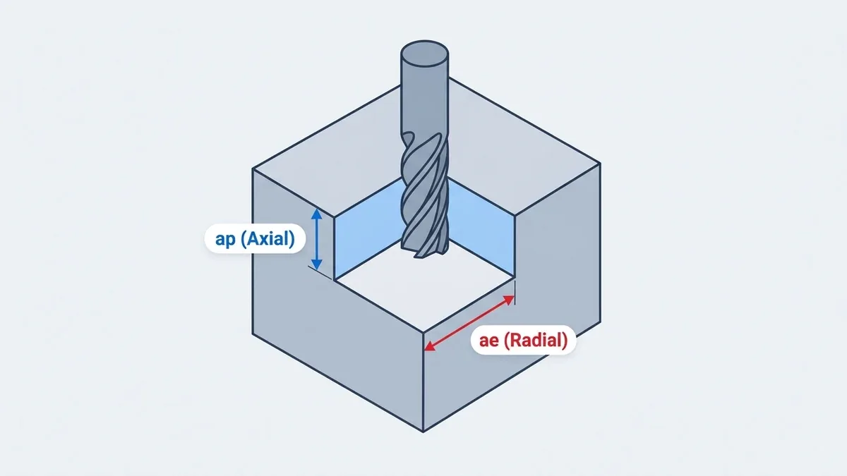
In modern machine shops, cut engagement is separated into two orthogonal axes: axial depth of cut (ap), measured parallel to the tool centerline, and radial width of cut (ae), measured perpendicular to the spindle axis. Balancing this ratio prevents excessive radial forces that cause wall taper and carbide edge fracture.
At our in-house CNC machining facility, we calibrate axial and radial engagement across high-speed 3-axis and 4-axis Vertical Machining Centers (VMCs) and turning centers. Using High-Efficiency Milling (HEM) toolpaths on our precision CNC milling services, we routinely hold critical mating tolerances of ±0.010 mm to ±0.020 mm (±0.0004″ to ±0.0008″).
Executive Summary & Engineering Takeaways (BLUF)
- Orthogonal Engagement Kinematics: Axial depth of cut (ap) controls Z-axis flute contact length and distributes thermal load along the cutting edge, while radial width of cut (ae) governs XY stepover and lateral bending loads.
- HEM vs. Conventional Roughing: Replacing wide passes (ap = 0.5D–1.0D, ae = 50%–100% D) with High-Efficiency Milling (ap = 1.5D–2.0D, ae = 5%–12% D) and Radial Chip Thinning Factor (RCTF) feed compensation doubles MRR and triples carbide tool life.
- Cantilever Deflection Scaling: End-mill tip deflection (δ) scales with L3 ÷ deff4; doubling tool stickout (L) from 2D to 4D multiplies radial push-off error by 8× (0.0046 mm to 0.0368 mm on a ⌀12 mm cutter under 250 N load).
- Minimum Cut Thickness Thresholds: Work-hardening 304 and 316L stainless steels require roughing and semi-finishing passes ≥ 0.15–0.20 mm to shear beneath the strain-hardened skin, while lathe inserts require ap ≥ (2/3)rε for roughing and ap ≥ 0.25–0.50rε for finishing.
- Tolerances & Ex-Factory Lead Times: On BT40 VMCs (10,000–15,000 RPM), full-flute skim passes hold ±0.010 to ±0.020 mm (±0.0004″ to ±0.0008″) with ISO 2768-mK general tolerances, shipping ex-factory in 4–8 business days (as-machined) and 7–12 business days (finished).
Article Engineering Navigation
- 1. What Is Depth of Cut in CNC Machining? Axial (ap) vs. Radial (ae) Kinematics
- 2. Material Removal Rate (MRR) and High-Efficiency Milling (HEM) Chip Thinning Physics
- 3. Why Does Excessive Radial Depth of Cut Cause Tool Deflection and Wall Taper?
- 4. Roughing, Semi-Finishing, and Finishing Depth of Cut Progression
- 5. In-House VMC Shop-Floor Speeds, Feeds, and DOC Benchmarks by Alloy
- 6. Shop-Floor DFM Guidelines, Troubleshooting & Ex-Factory Lead Times
- 7. Technical Engineering FAQ
1. What Is Depth of Cut in CNC Machining? Axial (ap) vs. Radial (ae) Kinematics
Depth of cut in CNC machining defines the linear thickness of stock removed by a cutting tool in a single pass, measured perpendicular to the feed vector. In 3-axis and 4-axis VMC milling, axial depth of cut (ap) measures Z-axis step-down depth, while radial width of cut (ae) defines horizontal XY stepover.
Mechanically, the ratio between axial and radial engagement dictates how the resultant cutting force decomposes into tangential torque (Fc), axial thrust (Fa), and radial bending force (Fr). Axial thrust loads push directly upward into the rigid BT40 spindle taper, whereas radial forces push laterally against the unsupported overhang of the end mill.
As shown in the CAD schematic below, conventional roughing pairs a shallow axial step-down (ap = 0.5D–1.0D) with a wide radial stepover (ae = 50%–100% D), concentrating heat and notch wear at the bottom corner. High-Efficiency Milling (HEM) engages full flute length (ap = 1.5D–2.0D) with light radial width (ae = 5%–12% D).
In precision CNC turning operations, depth of cut (ap) is measured radially perpendicular to the lathe spindle centerline, reducing cylindrical bar diameter by twice the radial engagement via ap = (Dinitial − Dfinal) ÷ 2. Turning Material Removal Rate follows Qturn = Vc × fn × ap (cm³/min), where Vc is surface speed (m/min) and fn is feed (mm/rev).
For example, rough-turning a 4140 steel shaft from ⌀50.0 mm down to ⌀44.0 mm in one pass (ap = 3.0 mm) at Vc = 160 m/min and fn = 0.30 mm/rev yields Qturn = 160 × 0.30 × 3.0 = 144.0 cm³/min. Selecting the proper insert corner nose radius (rε) relative to ap prevents radial push-off and chatter:
- Turning Roughing Engagement (ap ≥ 0.67rε to 4rε): Keeping radial depth of cut at least two-thirds of the insert nose radius (e.g., minimum
ap ≥ 0.55 mmand optimal1.6–3.2 mmon a CNMG 120408 insert withrε = 0.8 mm, capped at≤ 2/3of cutting edge length) directs cutting forces axially toward the chuck jaws rather than pushing a slender shaft radially away. - Turning Finishing Minimum Cut (ap ≥ 0.25–0.50rε): During final OD/ID sizing, depth of cut must stay above 25% to 50% of the nose radius (e.g.,
ap = 0.10–0.20 mmon anrε = 0.4 mmDCMT finishing insert) so the shear zone cuts beneath the honed carbide edge radius and prevents ploughing, rubbing, and work-hardening. - Theoretical Turning Roughness (Rz & Ra): Feed per revolution (
fn ≤ 0.5rε) and nose radius govern peak-to-valley surface finish viaRz ≈ (fn2 ÷ [8 × rε]) × 1,000µm and arithmetic averageRa ≈ (fn2 ÷ [32 × rε]) × 1,000µm (Ra ≈ Rz ÷ 4); atfn = 0.10 mm/revandrε = 0.4 mm, theoreticalRz = 3.13 µmandRa ≈ 0.78 µm.
2. Material Removal Rate (MRR) and High-Efficiency Milling (HEM) Chip Thinning Physics
Material Removal Rate (MRR) quantifies the volume of stock evacuated per minute (cm³/min), directly governing spindle cycle time and roughing economics. In CNC milling, MRR is the product of axial depth of cut (ap), radial width of cut (ae), and table feed rate (Vf) divided by 1,000.
When radial stepover (ae) drops below 50% of cutter diameter (D), the radial engagement angle (φs = arccos[1 − 2ae ÷ D]) falls below 90°. Consequently, the actual maximum uncut chip thickness (hex) becomes substantially thinner than the programmed feed per tooth (fz), causing the cutting edge to rub instead of shear.
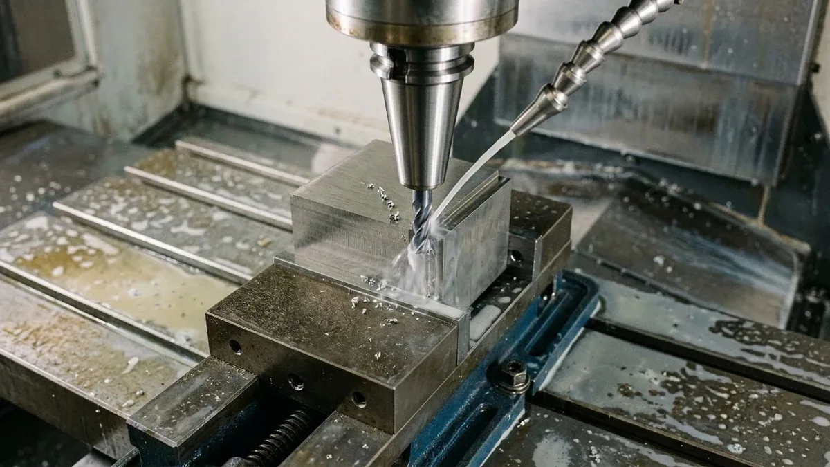
To prevent rubbing and work-hardening during dynamic trochoidal milling, CAM programmers multiply the target chip thickness (hex) by the Radial Chip Thinning Factor (RCTF). As demonstrated in our titanium setup below, pairing a deep axial cut with a 10% D radial stepover and RCTF-compensated feed evacuates heat into the chips efficiently.
📐 Shop-Floor Governing Equations & Worked HEM Calculation
Core Milling Kinematics: Spindle Speed n = (1,000 × Vc) ÷ (π × D) (RPM); Table Feed Vf = n × zn × fz (mm/min); and Material Removal Rate Qmill = (ap × ae × Vf) ÷ 1,000 (cm³/min).
Chip Thinning & Spindle Power: For ae < 0.5D, RCTF = 1 ÷ √[1 − (1 − 2ae ÷ D)2] = D ÷ (2 × √[ae × (D − ae)]) with fz = hex × RCTF; Net Cutting Power Pc = (ap × ae × Vf × kc) ÷ (60 × 106 × η) (kW).
Worked Example (4140 Steel): A ⌀12 mm 6-flute cutter at Vc = 180 m/min (4,775 RPM), ap = 22 mm, ae = 1.2 mm (0.10D), and hex = 0.06 mm gives RCTF = 1.667× (fz = 0.10 mm/tooth), yielding Vf = 2,865 mm/min, Qmill = 75.64 cm³/min, and Pc = 3.71 kW (kc = 2,500 N/mm², η = 0.85).
In CAM programming (Mastercam Dynamic Motion, Siemens NX Adaptive Milling, or HyperMILL), matching the exact RCTF multiplier to the radial engagement ratio keeps the physical chip load constant across tight corners and open channels:
- 50% to 100% D Stepover (ae ≥ 0.50D): Engagement angle reaches or exceeds 90°, so
hex = fzandRCTF = 1.00×(zero chip-thinning feed boost). - 25% D Stepover (ae = 0.25D): Engagement factor is
√(1 − 0.502) = 0.866, requiringRCTF = 1.155×feed compensation for semi-roughing in aluminum and engineering plastics. - 20% D Stepover (ae = 0.20D): Engagement factor is
√(1 − 0.602) = 0.800, requiring an exactRCTF = 1.250×feed boost. - 10% D Stepover (ae = 0.10D): Standard HEM roughing window for alloy steels and stainless steels;
√(1 − 0.802) = 0.600requires an exactRCTF = 1.667×multiplier. - 5% to 8% D Stepover (ae = 0.05D–0.08D): Used in Ti-6Al-4V and hardened steels;
ae = 0.08DrequiresRCTF = 1.843×, whileae = 0.05DrequiresRCTF = 2.294×to prevent edge rubbing.
3. Why Does Excessive Radial Depth of Cut Cause Tool Deflection and Wall Taper?
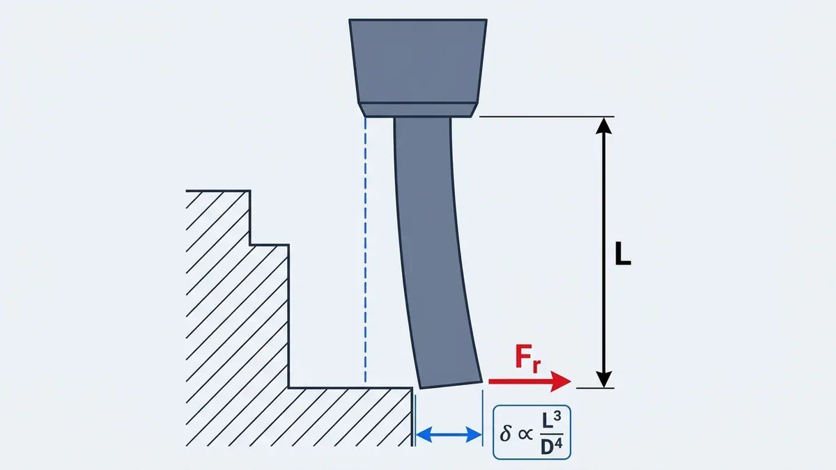
Excessive radial depth of cut (ae) generates high radial cutting forces (Fr) perpendicular to the spindle axis, bending the end mill like an elastic cantilever beam and producing tapered pocket walls. Because deflection follows δ = (Fr × L3) ÷ (3 × E × I), doubling tool stickout (L) multiplies tip deflection by 8× (23).
In a fluted solid carbide end mill, helical chip gullets reduce the structural cross-section, so the area moment of inertia I = (π × deff4) ÷ 64 is governed by the effective core diameter (deff ≈ 0.80D). Consequently, stepping down one tool size—or over-extending stickout—rapidly degrades wall perpendicularity (⊥).
As illustrated below, on a ⌀12 mm carbide cutter (E = 600 GPa, deff = 9.6 mm, I = 416.92 mm4) under Fr = 250 N, increasing stickout from 24 mm (2D) to 48 mm (4D) jumps deflection 8× from 0.0046 mm to 0.0368 mm, while 72 mm (6D) reaches 0.1243 mm.
Beyond cutter overhang, toolholder clamping stiffness and Total Indicator Readout (TIR) runout directly amplify radial cutting force variations. Standard ER32 collet chucks exhibit 0.010 to 0.015 mm runout and lower radial stiffness, whereas hydraulic chucks and DIN 69882-8 thermal shrink-fit holders hold TIR ≤ 0.003 mm so every flute shares an identical radial chip load.
4. Roughing, Semi-Finishing, and Finishing Depth of Cut Progression
Achieving tight Geometric Dimensioning and Tolerancing (GD&T) callouts requires separating stock removal into roughing, semi-finishing, and final skim finishing. After HEM roughing leaves 0.20 to 0.30 mm of radial stock, a semi-finishing pass (ae = 0.15 to 0.20 mm) removes deflection scallops so the finishing tool encounters a uniform chip load.
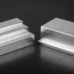
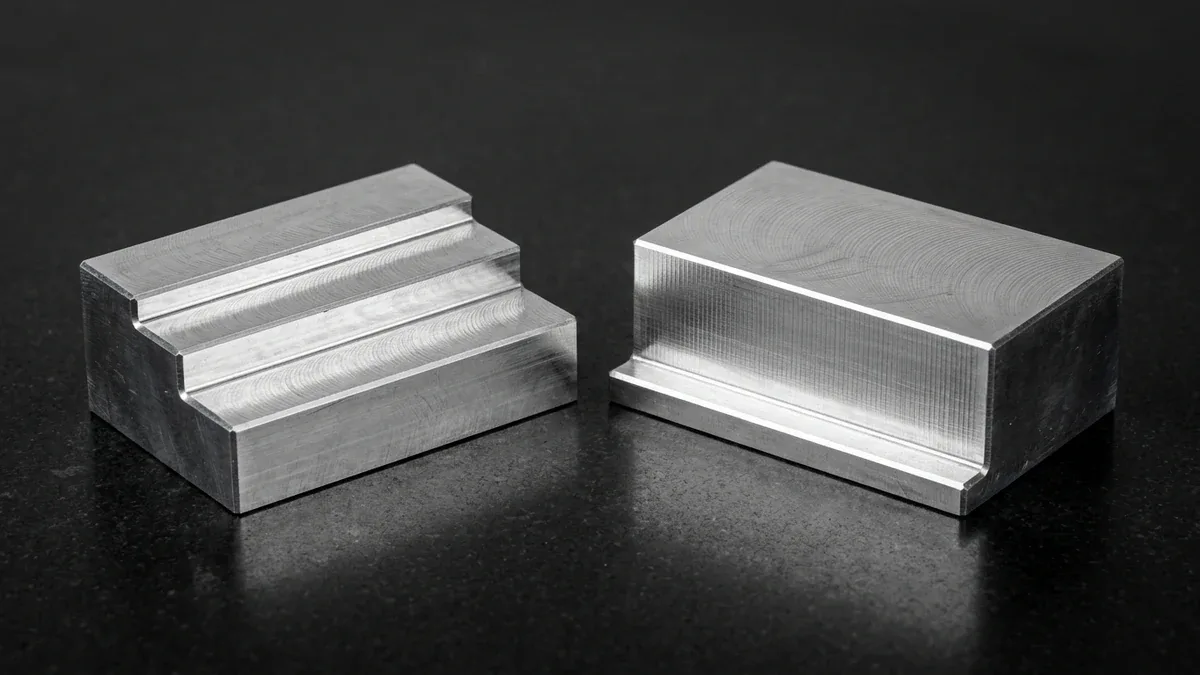
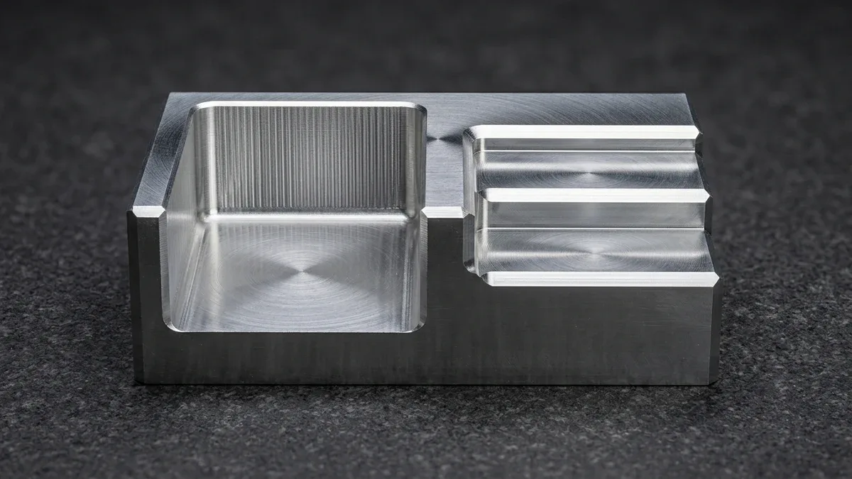
As seen on our 6061-T6 aluminum test block on the granite surface plate below, stepped axial roughing (2 mm, 8 mm, and 20 mm terraces) leaves horizontal witness lines. Executing a full-depth axial skim pass (ae = 0.05 to 0.10 mm) eliminates witness marks, holding ±0.010 to ±0.020 mm accuracy and 0.010 mm perpendicularity (⊥) at Ra 0.4–0.8 µm.
| Stage | Axial (ap) | Radial (ae) | Linear Tolerance | Roughness | Shop-Floor Application |
|---|---|---|---|---|---|
| Conventional Roughing | 0.5D–1.0D | 0.50D–1.00D | ±0.15 mm | Ra 3.2–6.3 µm | Open face milling and full-width channel slotting. |
| HEM Dynamic Roughing | 1.5D–2.5D | 5%–15% D | ±0.08 mm | Ra 1.6–3.2 µm | Trochoidal cavity pocketing in Al, SS, and Ti-6Al-4V. |
| Semi-Finishing | 1.0D–1.5D | 0.15–0.25 mm | ±0.03 mm | Ra 1.2–1.6 µm | Uniform stock equalization prior to final skim cut. |
| Skim / Spring Finishing | Full Wall (≤ 2D) | 0.04–0.10 mm | ±0.010–±0.020 mm | Ra 0.4–0.8 µm | ISO 286-2 H7 (+0.015/0 to +0.021/0 mm) bores, datums & perpendicularity ⊥ within 0.010 mm (general ISO 2768-mK). |
| Grinding / Wire EDM | Full Wall | 0.005–0.015 mm | ±0.005 mm (±0.0002″) | Ra 0.1–0.4 µm | Hardened tool steel inserts, precision dowel fits, and flatness ⏥ within 0.005 mm. |
5. In-House VMC Shop-Floor Speeds, Feeds, and DOC Benchmarks by Alloy
In our in-house machine shop, 75% to 85% of prismatic enclosures, heat sinks, and brackets run on high-speed 3-axis and 4-axis VMCs with BT40 spindles (10,000 to 15,000 RPM), reserving 5-axis machining centers for complex aerospace contours. Wrought aluminum (6061-T6, 7075-T651) runs at 250 to 450 m/min using 3-flute ZrN/DLC carbide end mills with flood coolant.
When heavy roughing removes over 60% of billet volume on thin-base aluminum plates, residual stresses can warp flatness (⏥) before finishing. Leaving 0.20–0.30 mm semi-finish stock, we stress-relieve 6061-T6 at 150–165 °C (302–329 °F), whereas 7075-T651 is strictly capped at ≤ 100–110 °C (212–230 °F) or unclamped for room-temperature relaxation to prevent over-aging softening.
Conversely, austenitic stainless steels (304, 316L) and precipitation-hardening 17-4 PH work-harden rapidly, while Ti-6Al-4V Grade 5 concentrates thermal energy directly at the carbide edge. In 304 and 316L stainless, roughing and semi-finishing passes must stay ≥ 0.15 to 0.20 mm so the tooth shears beneath the work-hardened layer left by the preceding flute.
| Material Grade | Speed Vc | HEM (ap / ae) | Skim (ap / ae) | Chip hex (Prog. fz) | Shop-Floor Tooling & Coolant |
|---|---|---|---|---|---|
| Aluminum 6061-T6 | 300–450 m/min | 1.5D–2.5D / 12%–25% D | 1.5D / 0.05–0.12 mm | 0.08–0.16 mm (fz 0.11–0.25) | 3-flute 45° polished ZrN/DLC carbide, flood coolant. |
| Aluminum 7075-T651 | 250–400 m/min | 1.5D–2.0D / 10%–20% D | 1.5D / 0.05–0.10 mm | 0.07–0.14 mm (fz 0.10–0.22) | 3-flute ZrN/DLC carbide, flood coolant (bake ≤ 110 °C). |
| Stainless 304 / 316L | 70–110 m/min | 1.5D–2.0D / 8%–12% D | 1.0D / 0.06–0.10 mm | 0.04–0.08 mm (fz 0.07–0.14) | 5-flute variable-helix AlTiN; rough DOC ≥ 0.15 mm. |
| 17-4 PH Stainless (Cond. A/H900) | 65–100 m/min | 1.2D–1.8D / 8%–10% D | 1.0D / 0.05–0.08 mm | 0.04–0.08 mm (fz 0.06–0.13) | 5-flute TiSiN/AlTiN carbide, high-pressure flood coolant. |
| 4140 Alloy Steel (28–32 HRC) | 120–180 m/min | 1.5D–2.0D / 8%–14% D | 1.2D / 0.04–0.08 mm | 0.05–0.10 mm (fz 0.08–0.17) | 6-flute TiAlN carbide, compressed air blast / MQL. |
| Ti-6Al-4V Grade 5 Titanium | 45–65 m/min | 1.5D–2.0D / 6%–10% D | 1.0D / 0.04–0.08 mm | 0.04–0.07 mm (fz 0.07–0.13) | 6-flute shrink-fit AlTiN carbide, high-flow flood coolant. |
| Engineering Plastics (PEEK / POM) | 200–400 m/min | 1.0D–2.0D / 15%–30% D | 1.0D / 0.08–0.15 mm | 0.08–0.16 mm (fz 0.10–0.25) | 2/3-flute razor-sharp uncoated polished carbide, air blast. |
6. Shop-Floor DFM Guidelines, Troubleshooting & Ex-Factory Lead Times
Designing cavities around rigid tool stickout ratios reduces cycle times and eliminates rework during First Article Inspection (FAI) in our 20 °C ± 1 °C climate-controlled metrology room. In our in-house machine shop, we resolve depth-of-cut defects using a closed-loop Symptom → Root Cause → Corrective Action protocol:
- Deep-Pocket Wall Taper (7075-T651 Aluminum): A 35 mm deep pocket shows +0.045 mm lower wall taper and chatter (Ra > 3.2 µm) because R2.0 mm corners forced a slender ⌀4 mm cutter at 9:1 L/D. Corrective Action: Relax internal corner radii to R4.5 mm so a rigid ⌀8 mm cutter (4.5:1 L/D) in a shrink-fit holder executes a 0.06 mm skim pass, restoring perpendicularity (⊥) within 0.012 mm and ±0.012 mm linear accuracy.
- Premature Edge Chipping & Notch Wear (316L Stainless): A 0.08 mm semi-finishing pass causes rapid flank wear and +0.035 mm bore undersize within 15 minutes because the cutting edge rubs inside the work-hardened layer from prior roughing. Corrective Action: Increase semi-finishing radial depth to
ae = 0.20 mm(hex = 0.06 mm) to shear beneath the strain-hardened skin, followed by a single sharp-edge 0.06 mm finish pass. - Thin-Wall Push-Off & Burr Rollover (PEEK & Thin 6061-T6 Ribs): Milling a 1.0 mm thick, 18 mm tall rib in one full-flute pass bends the unsupported wall away from the cutter, leaving a thicker top edge. Corrective Action: Program alternating-side stepped axial passes (
ap = 2.0–3.0 mmper Z-level, finishing top-to-bottom while uncut lower stock supports the wall).
When preparing 3D CAD models (STEP/IGES) and 2D tolerance drawings for custom CNC machining production, hardware engineering teams should apply five core Design for Manufacturability (DFM), metrology, and scheduling rules to balance tool rigidity, surface finish, and delivery:
- Limit Pocket Depth to 3:1–4:1 L/D: Specify internal vertical corner radii ≥ 1/3 of pocket depth plus 0.5 mm clearance (e.g., R4.5 mm for a 24 mm deep pocket to accommodate a ⌀8 mm end mill without corner-plunge chatter).
- Isolate Critical Mating Tolerances: Assign ±0.010 to ±0.020 mm (±0.0004″ to ±0.0008″) and ISO 286-2 H7 (+0.015/0 to +0.021/0 mm for ⌀6–30 mm) bore fits strictly to functional bearing journals, dowel holes, and sealing faces, applying ISO 2768-mK to non-critical stock surfaces.
- Brace Thin Walls & Floor Webs: Maintain minimum wall thickness ≥ 0.8–1.0 mm for metals and ≥ 1.5 mm for PEEK/POM, adding R1.0–R2.0 mm floor fillets so stepped axial passes prevent regenerative vibration.
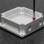
- Align Inspection with Shop-Floor Metrology: We verify finished features using our Zeiss Bridge CMM (available upon request for rigid prismatic parts), 2.5D Optical Video Measuring System (VMS), Mitutoyo 3-point internal bore micrometers, Class ZZ GO/NO-GO pin gauges, ISO 1502 / ASME B1.2 thread gauges, and ISO 4287 contact stylus profilometers (Ra / Rz).
- Separate Ex-Factory Turnaround from Air Transit: DFM reviews and quotes return within 24 hours (24–48 hours for complex tooling). As-machined CNC prototypes ship in 4 to 8 business days, surface-finished parts (MIL-A-8625 Type II/III anodizing, ASTM A967 passivation, ASTM B733 ENP) in 7 to 12 business days, and production batches (10 to 1,000+ units) in 7 to 30 business days—all as Ex-Factory Production & Inspection Turnaround, separate from 3 to 5 business days DHL/FedEx/UPS air transit.
🔗 Related CNC Machining & Metrology Engineering Guides
- Explore our 5-Axis Simultaneous & 3+2 Indexed CNC Machining Services for complex aerospace contours where tilted stub tooling eliminates long-stickout deflection.
- Read our CNC Machining Parameters: Cutting Speed, Feed Rate & Chip Load Guide to synchronize axial depth of cut with feed per tooth and surface footage.
- Review our CNC Spindle Speed RPM & Torque Optimization Guide to match BT40 spindle horsepower curves against heavy roughing and high-speed finishing passes.
7. Technical Engineering FAQ
Axial depth of cut (ap) is the vertical step-down parallel to the spindle axis, whereas radial width of cut (ae) is the horizontal stepover perpendicular to the tool. High-Efficiency Milling pairs deep axial cuts (1.5D–2.0D) with light radial stepovers (5%–12% D) to minimize tool deflection.
End-mill deflection scales with the cube of stickout length (L³) and inversely with the fourth power of cutter diameter (D⁴), so doubling overhang multiplies radial deflection by 8×. Keeping stickout below 3:1 L/D with a 0.05 mm skim pass holds ±0.010 to ±0.020 mm tolerances.
Austenitic 304 and 316L stainless steels work-harden rapidly during cutting, leaving a deformed, hardened skin on the machined surface. Taking a roughing pass shallower than 0.15 to 0.20 mm forces the carbide edge to rub inside this hardened zone, causing extreme heat and notch wear.
Our in-house facility returns DFM quotes within 24 hours, completing as-machined CNC prototypes in 4–8 business days and finished parts in 7–12 business days. All schedules represent Ex-Factory Production and Inspection Turnaround, separate from 3–5 business days DHL, FedEx, or UPS air transit.
Ready to Optimize Your Custom CNC Machined Parts?
Upload your 3D CAD models (STEP/IGES) and 2D tolerance drawings for a comprehensive manufacturability review, toolpath deflection analysis, and custom production quotation from our in-house engineering team.
Upload 3D CAD for DFM & Quote →