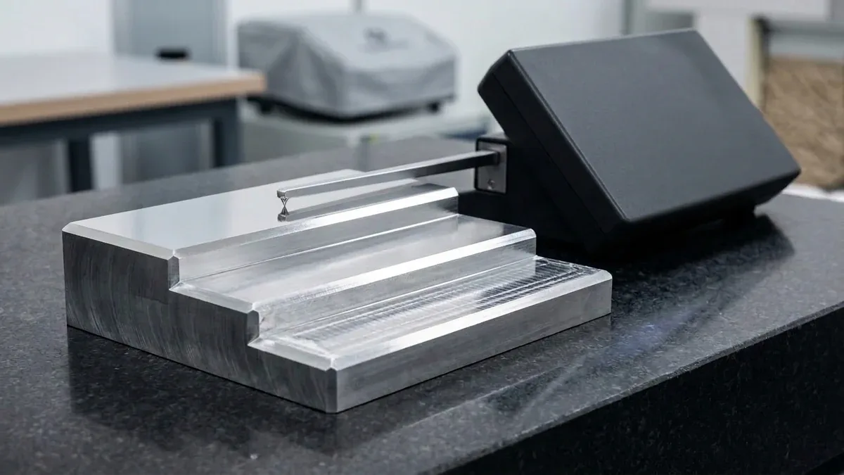
Precision metal removal requires meticulous coordination between cutting tool dynamics and workpiece material properties. Calculating optimal CNC machining parameters directly prevents tool breakage, chatter vibrations, and excessive thermal distortion. Consequently, process engineers calibrate speeds and feeds systematically for every operation.
Machining physics revolves around the shear zone where carbide flutes contact raw material. If spindle speeds run too high, frictional heat degrades cutting edges prematurely. Conversely, insufficient feed rates cause rubbing, work hardening, and severe surface roughness.
At AS Prototypes, our CNC machining facility uses advanced toolpath algorithms to maximize material removal rates. Furthermore, our high-speed CNC milling centers routinely hold critical feature tolerances within ±0.010 mm (±0.0004″) across demanding alloys (with ±0.005 mm / ±0.0002″ achieved via precision surface/cylindrical grinding and slow-feeding Wire EDM).
Executive Summary & Engineering Takeaways (BLUF)
- Core Focus & DFM Scope: Actionable shop-floor engineering guidelines for CNC Machining Parameters, covering material selection, geometric tolerancing, and defect prevention.
- Achievable Tolerance Envelope: General features hold ISO 2768-mK; critical bearing bores, dowel pins, and mating datums hold ±0.010 to ±0.020 mm (±0.0004″ to ±0.0008″), with Wire EDM/grinding to ±0.005 mm (±0.0002″).
- Machining & Surface Integrity: High-speed 3-axis and 4-axis VMCs (with simultaneous 5-axis for complex contours) delivering as-machined Ra 0.8 µm (32 µin) to Ra 0.4 µm (16 µin) per ASME B46.1.
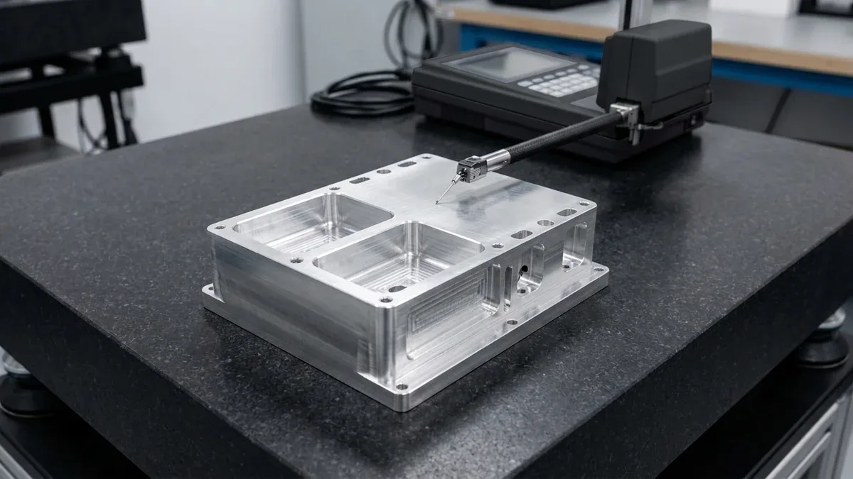
- Metrology & Process Control: On-machine spindle probing paired with 20°C (68°F) climate-controlled Zeiss CMM coordinate verification and calibrated Go/No-Go plug/ring gauges.
- Ex-Factory Turnaround: 4 to 8 business days for as-machined rapid prototypes; 7 to 12 business days for anodized, plated, or multi-operation production runs (excluding 3–5 days air transit).
Article Engineering Navigation
1. The Fundamental Machining Equations
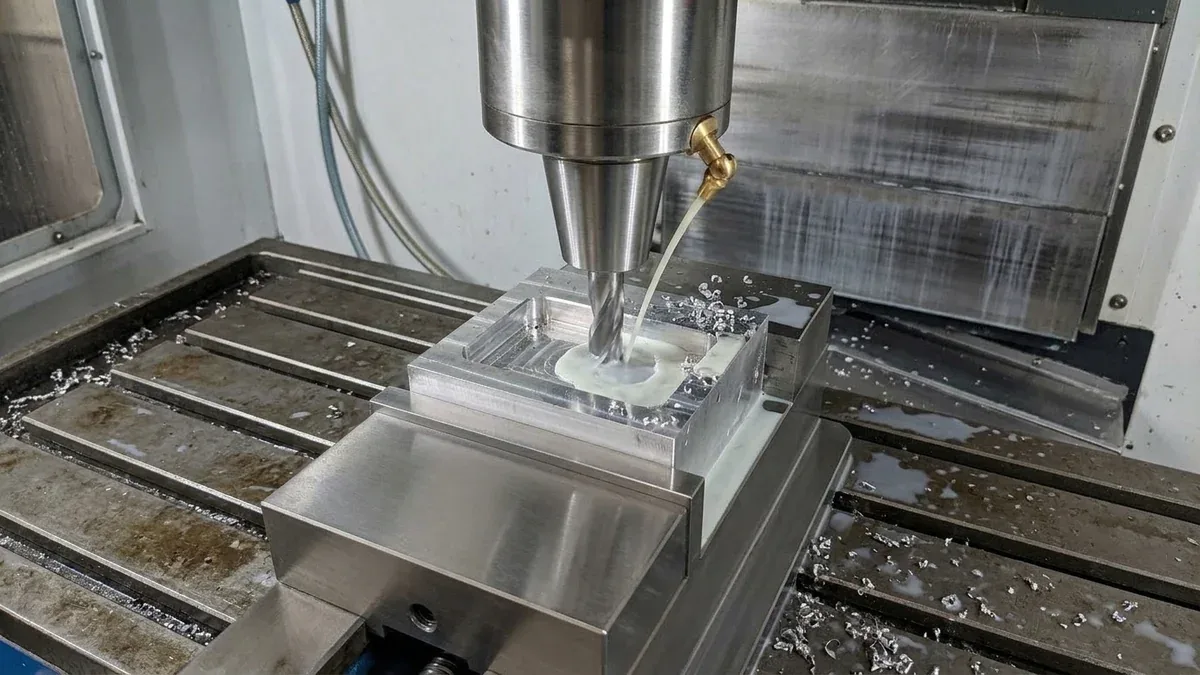
Machinists calculate primary parameters using standardized kinematic formulas.
First, cutting speed (Vc) measures peripheral tool surface speed in meters per minute. Tool manufacturers prescribe recommended Vc values based on workpiece hardness and cutter coating.
Second, spindle speed (N in RPM) translates linear cutting speed into rotational velocity. Specifically, the formula depends directly on cutter diameter and target cutting speed.
Third, table feed rate (Vf in mm/min) governs linear machine travel speed. Feed rate derives from spindle RPM multiplied by tooth count and chip load per tooth.
| Machining Parameter | Symbol & Unit | Standard Mathematical Formula | Engineering Objective |
|---|---|---|---|
| Spindle Speed | N (RPM, rev/min) | N = (Vc × 1000) / (π × D) | Maintains optimal tangential velocity at the cutter flute edge. |
| Table Feed Rate | Vf (mm/min) | Vf = N × fz × z | Dictates machine axis advance rate relative to tooth engagement. |
| Chip Load (Feed per Tooth) | fz (mm/tooth) | fz = Vf / (N × z) | Ensures true chip shear without tool rubbing or flute overload. |
| Material Removal Rate | MRR (cm³/min) | MRR = (ap × ae × Vf) / 1000 | Quantifies overall volumetric cutting productivity and spindle power. |
2. Material-Specific Cutting Parameters
Workpiece metallurgy dictates appropriate speed and feed envelopes. Machining ductile aluminum permits exceptionally high speeds. In contrast, heat-resistant superalloys demand conservative feeds and rigid setups.
| Workpiece Material | Cutting Speed Vc (m/min) | Feed per Tooth fz (mm/tooth) | Coolant & Tooling Strategy |
|---|---|---|---|
| Aluminum (6061-T6 / 7075-T6) | 300 – 800 m/min | 0.05 – 0.20 mm | High flood coolant, polished 2-3 flute uncoated carbide cutters. |
| Medium Carbon Steel (1045) | 150 – 250 m/min | 0.04 – 0.12 mm | Synthetic emulsion flood, TiAlN coated 4-flute end mills. |
| Stainless Steel (304 / 316L) | 80 – 160 m/min | 0.03 – 0.08 mm | High pressure coolant, positive rake geometry to avoid work hardening. |
| Titanium (Ti-6Al-4V Grade 5) | 40 – 80 m/min | 0.03 – 0.06 mm | Through-spindle high-pressure coolant, rigid fixturing, low tool overhang. |
| Engineering Plastics (POM / PEEK) | 200 – 500 m/min | 0.08 – 0.25 mm | Sharp polished edges, cold air blast or light coolant to prevent thermal melting. |
3. Axial and Radial Depth of Cut: Dynamic Chip Thinning
Modern CAM programming utilizes trochoidal and dynamic milling toolpaths. Dynamic toolpaths avoid heavy radial engagement. Instead, cutters take deep axial passes with light radial stepover.
When radial stepover drops below thirty percent of cutter diameter, chip thinning occurs. Consequently, the actual chip thickness becomes smaller than the programmed feed per tooth. To compensate, machinists increase feed rates significantly without raising cutting force.
Furthermore, dynamic milling distributes wear evenly along the entire carbide flute length. As a result, tool longevity triples while cycle times decrease substantially.
4. Surface Finish Optimization Guidelines
Achieving superior cosmetic finishes requires balancing cutting parameters during final finishing passes:
First, reduce feed per tooth during finish contouring. Smaller stepover increments reduce cusp heights, yielding Ra 0.8 μm surfaces directly off the machine.
Second, minimize tool overhang length. Longer tool extensions amplify bending deflection and cause harmonics chatter. Maintain a length-to-diameter ratio below 4:1 whenever possible.
Third, maintain climb milling direction. Climb milling ensures maximum chip thickness at entry and zero thickness at exit. Consequently, tool rubbing and built-up edge defects disappear.
5. Why Do Precision CNC Components Fail Tight Tolerances in Production, and How Do You Prevent It?
Maintaining repeatable accuracy in optimized speed-and-feed CNC machining requires controlling radial tool deflection, internal residual stress relaxation, and thermal expansion drift across multi-axis setups. While general unmated features reliably conform to ISO 2768-mK, holding critical mating bores and datum surfaces within ±0.010 mm (±0.0004″) demands staged roughing-to-finishing stress relief and rigid workholding.
Shop-Floor Quantitative Derivation: Cantilever Tool Deflection & Thermal Drift Compensation
In our Shenzhen CNC machine shop, preventing wall taper and bore bell-mouthing in optimized speed-and-feed CNC machining begins with calculating cantilever end-mill deflection (δ) before releasing G-code to the spindle. Modeled as a cylindrical carbide beam of diameter D and stickout length L subjected to radial cutting force Fr, tool deflection follows the fourth-power stiffness law:
δ = (64 × Fr × L³) / (3 × π × E × D⁴)
For a solid carbide end mill (E = 600 GPa / 87,000 ksi) with diameter D = 8.0 mm (0.315″), stickout L = 36 mm (4.5×D), and radial cutting load Fr = 180 N (40.5 lbf), the resulting deflection is δ = (64 × 180 × 36³) / (3 × 3.1416 × 600,000 × 4,096) = 0.0232 mm (0.00091″)—instantly consuming a ±0.010 mm (±0.0004″) drawing tolerance!
By stepping up to a D = 10.0 mm (0.394″) corner-radius tool and reducing stickout to L = 28 mm (2.8×D) with a 0.15 mm (0.006″) semi-finishing spring pass (Fr = 45 N), radial deflection drops to δ = 0.0011 mm (0.00004″), locking true position and cylindricity well within print limits.
Step-by-Step Shop-Floor Execution & Quality Protocol
To bridge CAD intent with repeatable shop-floor delivery, our engineering team enforces a four-stage execution workflow across every prototype and low-volume production batch:
- Step 1: Datum Hierarchy & 3/4/5-Axis Workholding Design: Align primary, secondary, and tertiary GD&T datums (A-B-C) with precision Kurt vises, custom-contoured 6061 aluminum soft jaws, or zero-point pneumatic pallets to minimize re-clamping datum shift.
- Step 2: Roughing & Intermediate Stress-Relief Stabilization: Execute high-efficiency trochoidal roughing leaving 0.30 to 0.50 mm (0.012″ to 0.020″) uniform stock, followed by unclamping or thermal stress-relief stabilization to release rolled-billet internal tension.
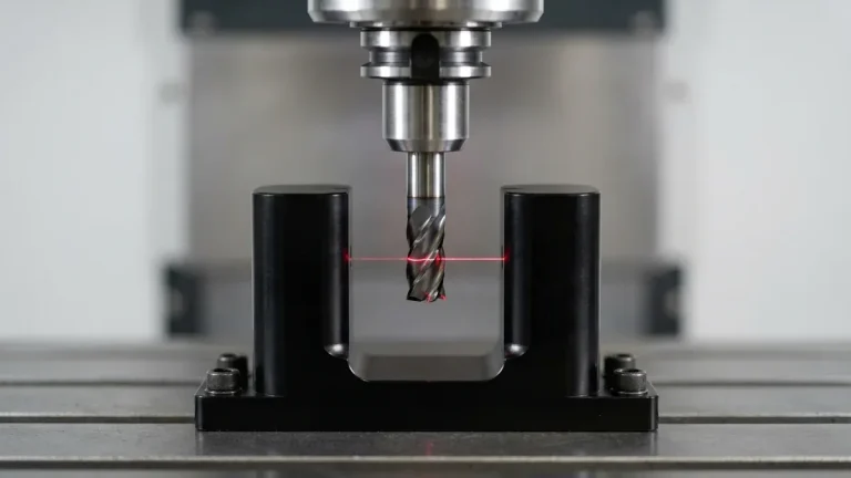
- Step 3: On-Machine Probing & Climate-Controlled Finishing: Re-probe work coordinate offsets via infrared spindle touch probes in a 20°C (68°F) shop environment, then execute climb-milling finish passes to achieve Ra 0.4–0.8 μm (16–32 μin).
- Step 4: Zeiss CMM Verification & Surface Treatment Masking: Perform first-article and batch inspection on programmable Zeiss CMM systems (available upon request for critical tolerances), applying silicone plugs to H7 bores and tapped threads prior to MIL-A-8625 anodizing or electroless nickel plating (whereas ASTM A967 stainless passivation adds zero measurable thickness and requires no masking).
Shop-Floor Defect Troubleshooting & Corrective Action Matrix
When evaluating part geometry during pre-production DFM review, our manufacturing engineers screen for the following failure modes and apply proven corrective controls:
| Defect / Symptom | Physical Root Cause | Shop-Floor Corrective Action | Recommended DFM Spec Limit |
|---|---|---|---|
| Thin-Wall Warpage & Bowing | Asymmetric removal of rolled skin releasing internal residual stress or excessive clamping jaw pressure | Alternate roughing passes symmetrically across both sides, leave 0.4 mm stock for stress relaxation, and finish-mill in low-pressure contoured soft jaws. | Flatness ≤ 0.02 mm / 100 mm |
| Deep Pocket Wall Taper & Chatter | Tool stickout exceeding L/D > 4:1 causing harmonic regeneration and radial tool push-off | Maximize internal corner radii (R ≥ 1/3 cavity depth) to permit larger-diameter stubby carbide tools and apply variable-helix climb milling. | Optimal pocket L/D ≤ 4:1 |
| Bore Out-of-Roundness (3-Lobing) | Three-jaw chuck clamping distortion on thin-walled rings or thermal spindle growth | Switch to full-wrap pie jaws or vacuum fixtures, execute a zero-offset spring boring pass, and verify with air/plug gauges before unclamping. | Cylindricity ≤ 0.008 mm |
| Post-Coating Thread / Bore Binding | Failure to account for 10–50 μm (0.4–2.0 mil) dimensional buildup from Type II/III anodizing or electroless nickel | Mask critical H7 bores with silicone plugs or pre-machine pitch/bore diameters oversize by 2× coating thickness per surface. | Masking on tolerances ≤ ±0.02 mm |
Engineering Trade-Offs: When NOT to Over-Specify
When to Avoid Over-Specifying (Engineering Cost-Tolerance Trade-Offs): Never apply blanket ±0.005 to ±0.010 mm (±0.0002″ to ±0.0004″) tolerances or simultaneous 5-axis callouts across non-mating exterior surfaces and clearance brackets.
Tightening a non-critical feature from standard ISO 2768-mK (±0.10 to ±0.20 mm) to ±0.010 mm increases cycle time and inspection overhead by 2.0× to 3.5× due to mandatory semi-finishing passes, thermal soak cycles, and 100% CMM probing. Reserve tight tolerances strictly for functional bearing journals, dowel pins, and sealing faces, while letting 3-axis and 4-axis VMCs handle prismatic geometry efficiently.
🔗 Related CNC DFM & Metrology Engineering Guides:
To further optimize cycle time and dimensional stability in optimized speed-and-feed CNC machining, combine proper internal corner relief with datum-based coordinate inspection. Consult our shop-floor engineering guides on Maintaining Dimensional Stability in Thin-Wall Machining, Eliminating Sharp Internal Corners & Tool Deflection, and Precision CMM Metrology & GD&T Verification.
6. Technical Engineering FAQ
Excessive cutting speed generates extreme frictional heat. Consequently, carbide cutting tools experience accelerated flank wear and premature edge failure. At AS Prototypes, our engineering team validates these parameters against ISO 2768-mK general tolerances (with critical mating features held to ±0.010 mm / ±0.0004″) and provides 24-hour DFM feedback.
When radial stepover drops below 30% of tool diameter, the effective chip thins out. Machinists must increase feed rates to maintain true chip load. At AS Prototypes, our engineering team validates these parameters against ISO 2768-mK general tolerances (with critical mating features held to ±0.010 mm / ±0.0004″) and provides 24-hour DFM feedback.
Climb milling cuts from thick to thin chip profiles. Therefore, it reduces tool deflection, generates less heat, and produces superior surface finishes. At AS Prototypes, our engineering team validates these parameters against ISO 2768-mK general tolerances (with critical mating features held to ±0.010 mm / ±0.0004″) and provides 24-hour DFM feedback.
Partner with Our Precision CNC Machining & Engineering Team
Eliminate tool deflection, residual stress distortion, and tolerance stack-up risks before production begins. Upload your 3D CAD files (STEP/IGES) and 2D GD&T drawings for a comprehensive shop-floor DFM review and custom quotation.
Upload 3D CAD for Engineering DFM & RFQ