In precision mechanical assemblies, threaded bolts generate axial clamping preload rather than absorbing transverse shear or establishing datum alignment. Standard bolt clearance holes introduce 0.20 mm to 0.50 mm of radial play, allowing positional drift under dynamic vibration. Selecting the right types of pins locks planar coordinates, eliminates backlash, and transfers shear loads across gearboxes, mold bases, and linkages.
Different pin geometries govern distinct mechanical constraints. Cylindrical dowel pins (ISO 2338 and ISO 8734) use interference or transition fits in H7 reamed bores to lock planar translation. Conversely, 1:50 taper pins (ISO 2339) wedge radially, spring pins (ISO 8750 and ISO 8752) flex in drilled holes, and clevis pins (ISO 2341) pivot under double shear.
At our in-house CNC machining facility, we manufacture custom locating dowels, diamond pins, and cross-drilled clevis shafts. Combining Swiss-type sliding-headstock CNC turning (±0.010 to ±0.020 mm) with centerless OD grinding holding ±0.005 mm (±0.0002″) and surface roughness Ra 0.2–0.4 µm per ISO 4287 prevents radial deflection and galling.
Executive Summary & Engineering Takeaways (BLUF)
- Dowel Grinding & ISO 286-2 Fits: ISO 2338 (unhardened) and ISO 8734 (58–62 HRC per ASTM E18) dowel pins are centerless ground to ±0.005 mm (±0.0002″). On ⌀8.000 mm nominal size, m6 (+0.006/+0.015 mm) pins pair with K7 (+0.005/−0.010 mm) or P7 (−0.009/−0.024 mm) press-fit bores and H7 (+0.015/0 mm) or F7 (+0.028/+0.013 mm) slip-fit bores, while h6 (0/−0.009 mm) pins provide precision H7 slip fits.
- Swiss Turning for Slender Pins: Guide-bushing Swiss lathes with synchronous sub-spindles hold ±0.010 mm to ±0.020 mm (±0.0004″ to ±0.0008″) on slender pins (L/D > 8:1), cross-holes, and retention grooves (general un-toleranced features per ISO 2768-mK).
- Round + Diamond Kinematic Pair: Pairing one cylindrical pin (locking X and Y) with one relieved diamond pin (locking rotational yaw θ) eliminates four-coordinate over-constrained binding across ±0.020 mm hole pitch tolerances.
- Blind-Hole Venting DFM: Specify a 0.2 to 0.5 mm longitudinal air-vent flat (or ⌀1.0 to 1.5 mm bottom bleed hole), 1.5 to 2.0 mm bottom chamfer clearance, and an ISO 8735 internal pull thread (M3–M10) to prevent pneumatic lock.
- Ex-Factory Turnaround: As-machined and ground prototype pins ship ex-factory in 4 to 8 business days; vacuum heat-treated, ASTM A967 passivated, or black-oxide pins ship in 7 to 12 business days (plus 3 to 5 business days air transit).
Article Engineering Navigation
- 1. Primary Classifications of Mechanical Pins: Locating vs. Fastening
- 2. Kinematic Datum Locating: H7 Fits & Round-Plus-Diamond Pins
- 3. Swiss-Type CNC Turning & Centerless OD Grinding Workflow
- 4. Shear Load Mechanics & Blind-Hole Dowel Pin DFM Guidelines
- 5. Metallurgical Selection Matrix & Alloy Trade-Offs
- 6. How to Troubleshoot Pin Failures, Verify GD&T & Plan Lead Times?
- 7. Technical Engineering FAQ
1. Primary Classifications of Mechanical Pins: Locating vs. Fastening
Mechanical engineers divide industrial pins into two functional groups: rigid datum-locating pins that enforce spatial repeatability, and semi-flexible or articulating fastener pins that transmit torque and dynamic shear. Selecting between ground dowels, conical tapers, swaged grooved pins, hollow spring tubes, or headed clevis shafts depends on bore preparation, disassembly frequency, and shock loading.
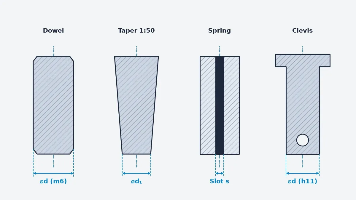
Whereas precision locating dowels require reamed or bored H7, K7, or P7 holes to establish micron-level coordinate references, compliant spring and grooved pins expand elastically or plastically inside standard H11 or H12 twist-drilled holes. As illustrated in the comparative CAD schematic below, each pin profile relies on a distinct radial retention mechanism.
- Cylindrical Parallel Dowel Pins (ISO 2338 / ISO 8734 / ISO 8733 / ISO 8735): Solid centerless-ground rods supplied unhardened (ISO 2338), through-hardened to 58–62 HRC per ASTM E18 (ISO 8734 / DIN 6325), or with an internal extraction thread and air-vent flat for blind holes (ISO 8733 unhardened / ISO 8735 hardened, DIN 7979) in m6 or h6 tolerance classes.
- 1:50 Conical Taper Pins (ISO 2339 / DIN 1 / ISO 8736): Feature a continuous 1:50 diametral taper (ΔD = L ÷ 50 = 0.02 × L, 1.146° included cone angle) that wedges into taper-reamed bores with zero radial play and releases cleanly via knock-out or threaded puller nuts.
- Cold-Swaged Grooved Pins (ISO 8740 / ISO 8744 / ISO 8745): Solid cylindrical shafts rolled with three longitudinal grooves spaced 120° apart; the displaced metal crests expand the effective OD by +0.15 mm to +0.35 mm to lock elastically inside unreamed H11 drilled holes.
- Slotted (ISO 8752) & Coiled Spiral Spring Pins (ISO 8750): Hollow roll-formed spring tubes engineered for H12 drilled holes; whereas slotted pins provide high static radial tension, 2.25-turn coiled spiral pins flex uniformly across 360° to dampen cyclic impact shock without slot-opposite fatigue cracking.
- Headed & Unheaded Clevis Pins (ISO 2341 / ISO 2340 / DIN 1444): Articulating pivot shafts featuring a flat circular flange head, a cross-drilled cotter-pin hole (sized for ISO 1234 split cotters or R-clips), and an f8 or h11 shaft tolerance running inside H9 or H11 yoke bores under double shear.
- Stepped Locating & Quick-Release Ball-Lock Pins: Custom Swiss-turned dual-diameter pins that bridge mismatched bore sizes across housing interfaces, or positive-locking detent pins with spring-loaded stainless steel balls for rapid tool-less fixture changeovers.
| Pin Family & Standard | Primary Function | Pin OD Tolerance | Mating Bore | Ra (µm) | Recommended Application |
|---|---|---|---|---|---|
| Dowel Pin (ISO 2338 / 8734) | Datum & shear lock | m6 or h6 (±0.005 mm) | Reamed H7 / K7 / P7 | 0.2–0.4 | Mold plates, gearboxes, fixtures |
| Blind Pull Dowel (ISO 8735) | Blind datum & extraction | m6 (±0.005 mm) | Reamed H7 / K7 | 0.2–0.4 | Blind housings & heavy dies |
| 1:50 Taper Pin (ISO 2339) | Conical radial wedging | 1:50 cone (d1 h10) | 1:50 taper reamed | 0.4–0.8 | Shaft hubs & service teardowns |
| Grooved Pin (ISO 8740) | 3-crest elastic lock | h9 (+0.25 mm crest) | Drilled H11 | 0.8–1.6 | Gear pinning without reaming |
| Slotted Spring Pin (ISO 8752) | Radial spring tension | +0.30/+0.60 mm free OD | Drilled H12 | 0.8–1.6 | General anti-rotation fastening |
| Coiled Spring Pin (ISO 8750) | 2.25-turn shock flex | +0.25/+0.55 mm free OD | Drilled H12 | 0.8–1.6 | High-vibration impact linkages |
| Clevis Pin (ISO 2341) | Double-shear pivot | f8 or h11 (±0.015 mm) | H9 / H11 yoke bore | 0.4–0.8 | Actuator yokes & hinge joints |
| Round + Diamond Pair | 3-DOF lock (X, Y, θ) | g6 / h6 (±0.005 mm) | Reamed H7 | 0.2–0.4 | Pallet changers & optical plates |
2. Kinematic Datum Locating: H7 Fits & Round-Plus-Diamond Pins
In precision fixture plates, gearbox housings, and injection mold bases, dowel pins establish the primary X-Y planar datum before clamping bolts are torqued. Under the ISO 286-2 press-fit tolerance system, engineers choose between a hole-basis fit (finishing all bores with standard H7 reamers) or a shaft-basis fit (pressing standard m6 or h6 ground pins into differentiated bores).
For ⌀8.000 to ⌀10.000 mm nominal dowel pins per ISO 286-2 (6–10 mm step), m6 pins measure +0.006/+0.015 mm and h6 pins measure 0/−0.009 mm (on ⌀6.000 mm, m6 is +0.004/+0.012 mm and h6 is 0/−0.008 mm). Pairing m6 pins with K7 or P7 bores guarantees press retention, while H7/h6, G7/m6, or F7/m6 provides slip alignment.
| ISO Fit Pairing | ⌀6.000 mm Bore / Pin (mm) | ⌀8.000–10.000 mm Bore / Pin (mm) | ⌀8.000–10.000 mm Fit Extreme (mm) | Fit Classification | Recommended Engineering Role |
|---|---|---|---|---|---|
| P7 / m6 | −0.008/−0.020 & +0.004/+0.012 | −0.009/−0.024 & +0.006/+0.015 | −0.015 to −0.039 (Interference) | Heavy Press Fit | Permanent thick-wall steel base anchor |
| N7 / m6 | −0.004/−0.016 & +0.004/+0.012 | −0.004/−0.019 & +0.006/+0.015 | −0.010 to −0.034 (Interference) | Medium Press Fit | Standard press-fit base for m6 pins |
| K7 / m6 | +0.003/−0.009 & +0.004/+0.012 | +0.005/−0.010 & +0.006/+0.015 | −0.001 to −0.025 (Interference) | Light Press Fit | Zero-play locating press in aluminum/steel |
| H7 / m6 | +0.012/0 & +0.004/+0.012 | +0.015/0 & +0.006/+0.015 | +0.009 to −0.015 (Transition) | Locating Transition | Hole-basis light tap/arbor locating fit |
| P7 / h6 | −0.008/−0.020 & 0/−0.008 | −0.009/−0.024 & 0/−0.009 | 0.000 to −0.024 (Interference) | Precision Press Fit | Fixed base press fit for h6 ground pins |
| H7 / h6 | +0.012/0 & 0/−0.008 | +0.015/0 & 0/−0.009 | 0.000 to +0.024 (Clearance) | Snug Locating Slip | Precision removable cover alignment |
| H7 / g6 | +0.012/0 & −0.004/−0.012 | +0.015/0 & −0.005/−0.014 | +0.005 to +0.029 (Clearance) | Close Sliding Fit | Frequent hand-removable fixture covers |
| G7 / m6 | +0.016/+0.004 & +0.004/+0.012 | +0.020/+0.005 & +0.006/+0.015 | −0.010 to +0.014 (Close Slip) | Precision Locating Slip | Snug cover bore over m6 press pin |
| F7 / m6 | +0.022/+0.010 & +0.004/+0.012 | +0.028/+0.013 & +0.006/+0.015 | −0.002 to +0.022 (Slip Fit) | Shaft-Basis Slip | Cover clearance bore over m6 press pin |
A frequent Design for Manufacturing (DFM) mistake on multi-pin housings is pressing two full-round cylindrical dowel pins into both mating plates. A rigid body resting on a flat datum plane possesses three planar degrees of freedom (X translation, Y translation, and yaw rotation θ), whereas two full-round pins attempt to lock four independent coordinates (X1, Y1, X2, Y2).
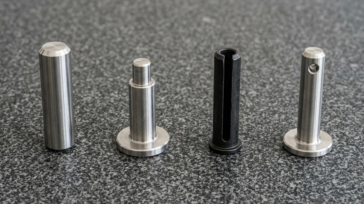
When center-to-center hole pitch varies by ±0.015 mm during CNC milling or experiences differential thermal growth, two full-round pins bind and gall during assembly. Our in-house engineering team resolves this over-constraint by pairing one full-round primary pin (locking X and Y) with one relieved diamond pin (locking only rotational yaw θ), alongside the pin families shown below.
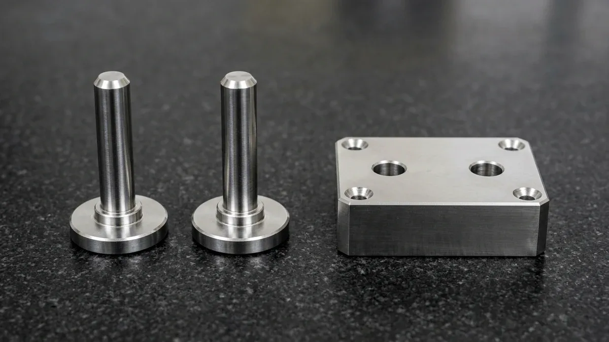
On the secondary diamond pin, two symmetrical relief flats leave a cylindrical land of width b = (0.12 to 0.20) × D absorbing ±0.025 mm pitch variation within 0.010 mm angular repeatability. Below, a mirror-ground cylindrical dowel pin, flanged stepped locating pin, black-oxide slotted spring pin, and headed clevis pin stand upright on the granite plate.
3. Swiss-Type CNC Turning & Centerless OD Grinding Workflow
Machining slender locating pins, stepped shafts, and clevis pivots with length-to-diameter (L/D) ratios exceeding 8:1 on a conventional turret chucking lathe causes radial tool deflection above 0.030 mm. Cutting forces push the unsupported bar away from the insert, producing barrel taper, chatter marks, and out-of-roundness that ruin press-fit repeatability.
Our turning department eliminates radial deflection by combining sliding-headstock Swiss-type CNC turning with through-feed and in-feed centerless OD grinding. This four-stage production sequence maintains cylindricity within 0.005 mm and mirror surface finishes on custom hardware like the 316L stainless clevis pin and yoke assembly shown below.
- Guide-Bushing Swiss Turning: Bar stock feeds through a carbide guide bushing positioned 1.0 to 1.5 mm behind the single-point diamond-ground carbide insert (Vc = 85–140 m/min, f = 0.03–0.07 mm/rev), holding ±0.010 mm to ±0.020 mm (±0.0004″ to ±0.0008″) and ISO 2768-mK on un-toleranced features.
- Synchronous Sub-Spindle & Live C-Axis Milling: A synchronized sub-spindle grips the leading shaft end before cutoff to prevent whip while live tooling mills 0.2–0.5 mm air-vent flats, diamond-pin relief surfaces, M3–M10 internal pull threads (ISO 8735), and deburred cross-holes.
- Vacuum Quenching & Triple Tempering: ISO 8734 and ISO 8735 blanks in GCr15 (52100) or 440C stainless retain +0.08 to +0.12 mm radial grinding stock before vacuum austenitizing, nitrogen gas quenching, and triple tempering to 58–62 HRC per ASTM E18 to transform retained austenite.
- Through-Feed & In-Feed Centerless OD Grinding: Hardened pins pass between a vitrified aluminum-oxide wheel (Vc = 35–45 m/s) and a tilted rubber-bonded regulating wheel on a 25°–30° carbide work-rest blade, holding ±0.005 mm (±0.0002″) OD tolerances, circularity within 0.005 mm, and Ra 0.2 to 0.4 µm per ISO 4287.
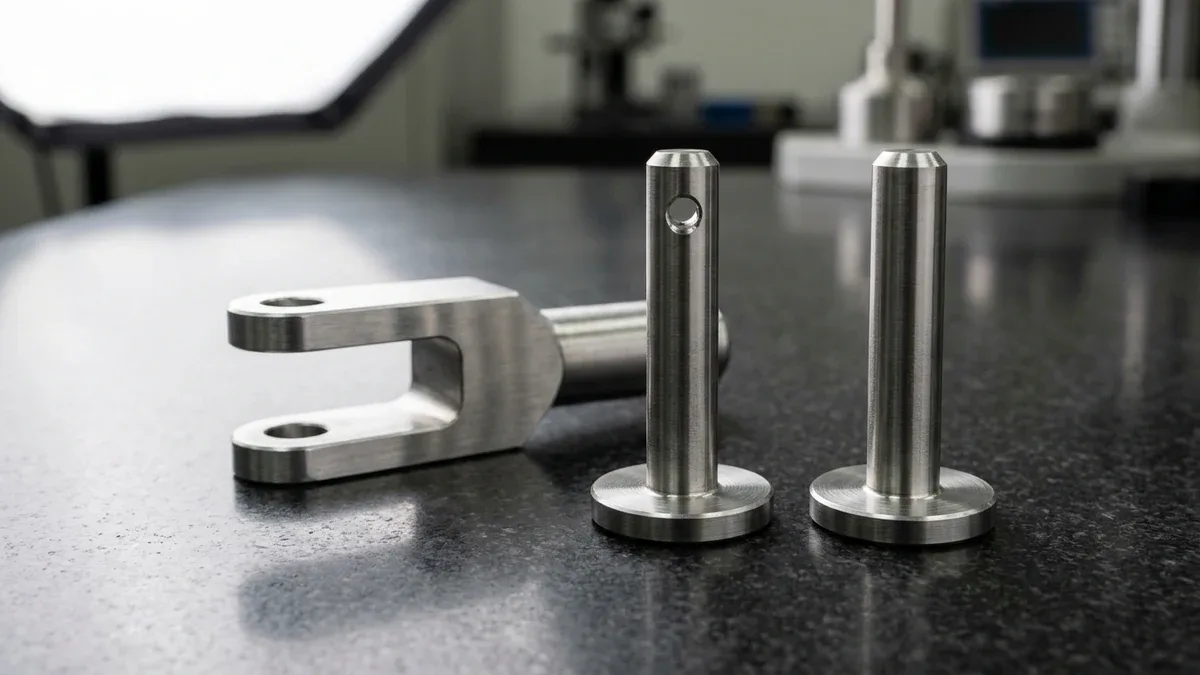
During centerless grinding, straight cylindrical dowels pass axially between the grinding wheel and tilted regulating wheel (through-feed mode), while stepped locating pins, headed clevis pins, and 1:50 taper pins are ground against a fixed end-stop (in-feed plunge mode). Setting the carbide work-rest blade at a 25° to 30° top angle breaks up odd-lobed harmonics.
| Pin Alloy Grade | Swiss Turning Vc (m/min) | Turning Feed f (mm/rev) | Pre-Grind Stock (mm) | Grinding Wheel Spec | Final OD Tolerance & Ra |
|---|---|---|---|---|---|
| GCr15 / AISI 52100 | 110–145 | 0.04–0.08 | +0.08 to +0.12 | WA80-100 K Vitrified | ±0.005 mm (m6/h6), Ra 0.2 µm |
| 440C Stainless Steel | 85–115 | 0.03–0.06 | +0.08 to +0.12 | PA/SG 80-100 J Vitrified | ±0.005 mm (m6/h6), Ra 0.2 µm |
| 17-4PH H900 Stainless | 75–105 | 0.03–0.06 | +0.06 to +0.10 | WA80 J/K Vitrified | ±0.005 mm to ±0.010 mm, Ra 0.3 µm |
| 303 / 316L Stainless | 90–130 | 0.03–0.07 | +0.05 to +0.08 | GC/WA 100 J Vitrified | ±0.005 mm to ±0.010 mm, Ra 0.4 µm |
| 4140 Quenched & Tempered | 100–135 | 0.04–0.08 | +0.08 to +0.10 | WA80 K Vitrified | ±0.005 mm to ±0.015 mm, Ra 0.4 µm |
| C3604 Free-Cutting Brass | 160–220 | 0.05–0.10 | Direct Swiss Finish | Polished PCD / Carbide | ±0.010 mm, Ra 0.4–0.8 µm |
4. Shear Load Mechanics & Blind-Hole Dowel Pin DFM Guidelines
When sizing a locating dowel, torque shear pin, or clevis pivot shaft, mechanical engineers must evaluate transverse shear stress, housing bore bearing pressure, and press-fit axial retention force. Whereas a cantilevered dowel pin acts in single shear across one joint plane, a clevis pin spanning two fork ears acts in double shear, doubling load capacity.
- Single-Shear vs. Double-Shear Capacity & Bore Bearing Stress: τsingle = 4F ÷ (πd2) and τdouble = 2F ÷ (πd2), so Fdouble = 2 × τallow × (π × d2 ÷ 4) ÷ SF (where τallow ≈ 0.577 × σyield). A ⌀6.000 mm dowel pin (As = πd2 ÷ 4 = 28.27 mm2 at working shear stress τallow = 460 MPa) carries 13.0 kN (13,006 N) in single shear versus 26.0 kN (26,012 N) in double shear; similarly, a ⌀8.00 mm (0.3150″) 17-4PH H900 pin (σyield = 1,170 MPa / 170 ksi, τallow ≈ 675 MPa / 97.9 ksi, A = 50.27 mm2 / 0.0779 in2, SF = 2.0) carries 16,966 N (16.97 kN / 3,814 lbf) in single shear and 33,932 N (33.93 kN / 7,628 lbf) in double shear. Across a central rod eye of thickness t = 12.0 mm, projected bore bearing stress is σbearing = F ÷ (d × t) = 33,932 N ÷ (8.00 mm × 12.0 mm) = 353.5 MPa (51.3 ksi).
- Press-Fit Interface Contact Pressure & Axial Pull-Out Force: For a solid steel pin (E = 200,000 MPa) pressed into a thick steel housing with diametral interference δ = 0.012 mm (12 µm) on d = 8.00 mm over engagement length Leng = 16.0 mm and oiled friction coefficient µ = 0.15: interface pressure p = (δ × E) ÷ (2 × d) = (0.012 × 200,000) ÷ 16.0 = 150.0 MPa (21.76 ksi). Contact area Acontact = π × d × Leng = 402.12 mm2, yielding axial press/pull-out force Faxial = µ × p × Acontact = 0.15 × 150.0 × 402.12 = 9,048 N (9.05 kN / 2,034 lbf / 0.92 tf).
- Thermal Pitch Drift Between Dissimilar Plates: ΔL = (αAl − αSteel) × L × ΔT = (23.0 − 11.5) × 10−6 °C−1 × 150 mm × 15°C = 0.0259 mm (0.0010″), requiring a relieved diamond secondary pin to prevent thermal binding.
- 1:50 Taper Pin Diameter Sizing (ISO 2339 / DIN 1): ΔD = Dlarge − d1 = L ÷ 50 = 0.02 × L. For a nominal small-end diameter d1 = 6.00 mm (0.2362″) pin of length L = 40 mm (1.5748″), ΔD = 0.80 mm, yielding Dlarge = 6.80 mm (0.2677″).
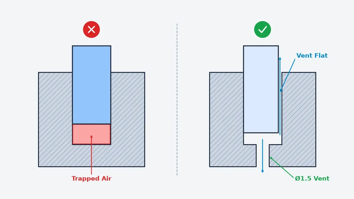
Beyond shear sizing, pressing a solid m6 dowel pin into an unvented blind H7 or K7 bore turns the pin into a sealed pneumatic and hydraulic piston. Trapped air and assembly oil compress at the hole bottom, generating back-pressure that pushes the pin back out or cracks thin-walled aluminum and cast-iron housing bosses.
As illustrated in the blind-hole DFM cross-section schematic below, our engineering team enforces five shop-floor design rules on every blind dowel installation to guarantee full seating depth, prevent boss splitting, and allow non-destructive field extraction during maintenance:
- Longitudinal Air-Vent Flat or Bottom Bleed Hole: Mill or grind a 0.2 to 0.5 mm deep longitudinal air-bleed flat along the cylindrical OD (standard on ISO 8735 pins), or drill a ⌀1.0 to 1.5 mm air-vent hole through the bottom of the blind housing bore.
- Bottom Chamfer & Reamer Lead Clearance: Machine the blind bore at least 1.5 to 2.0 mm deeper than the pin engagement length so the pin’s 15°–20° lead-in chamfer and the reamer’s 45° cutting lead never bottom out prematurely.
- Asymmetric Press-Plus-Slip Engagement Ratio: Anchor the dowel pin permanently into the base housing across a 1.5D to 2.0D press-fit depth (K7/m6 or P7/h6), and engage the removable cover across a 1.0D to 1.5D slip-fit depth (H7/g6 or H7/h6).
- Internal Pull-Out Extraction Threads (ISO 8733 / ISO 8735): Wherever a blind dowel cannot be knocked out from behind with a drift punch, specify an ISO 8733 (unhardened) or ISO 8735 / DIN 7979 (hardened) internally threaded dowel pin (M3, M4, M5, M6, or M8) for slide-hammer extraction.
- Minimum Housing Boss Wall Thickness: Maintain a radial boss wall thickness of at least 1.5 × D in steel housings and 2.0 × D in 6061-T6 or die-cast ADC12 aluminum housings to resist hoop tensile stress during press-fitting.
5. Metallurgical Selection Matrix & Alloy Trade-Offs
Material selection for mechanical pins requires balancing transverse shear yield, core and surface hardness, corrosion resistance, and tribological anti-galling behavior. A critical shop-floor rule is never pressing an unhardened 304 or 316L stainless steel dowel (~190 HV) into a 316L stainless housing bore—identical face-centered cubic (FCC) crystal lattices cold-weld immediately under interference pressure.
To prevent adhesive metal galling and seizure in stainless assemblies, specify precipitation-hardened 17-4PH H900 (40–44 HRC) or martensitic 440C stainless steel (58–62 HRC) to maintain at least a 10 HRC hardness differential against the bore. For dry mold bases and gearboxes, through-hardened 100Cr6 / GCr15 / SUJ2 (SAE 52100) bearing steel offers peak shear resistance.
When specifying surface treatments on precision m6 or h6 pins, engineers must account for dimensional coating growth. Citric or nitric acid passivation per ASTM A967 / AMS 2700 produces a ~2 nm passive oxide film with 0.000 mm dimensional change, whereas electroless nickel plating (ASTM B733) builds 100% outward (+2.0t on pin OD) and requires pre-grind compensation.
| Alloy Grade | Hardness (ASTM E18) | Ultimate Shear (MPa) | Post-Processing | OD Tolerance | Recommended Application |
|---|---|---|---|---|---|
| 100Cr6 / GCr15 / SUJ2 (52100) | 58–62 HRC | 1,150–1,300 | Black oxide / rust oil | ±0.005 mm (m6/h6) | ISO 8734 mold & die dowels |
| 440C Stainless Steel | 58–62 HRC | 1,050–1,180 | ASTM A967 passivated | ±0.005 mm (m6/h6) | Corrosive & medical dowels |
| 17-4PH H900 | 40–44 HRC | 820–900 (τy ≈ 675) | H900 age + ASTM A967 | ±0.005 to ±0.010 mm | High-load clevis & diamond pins |
| 4140 / 42CrMo4 Steel | 38–45 HRC Q&T (28–34 pre-hard) | 650–780 | Black oxide / ASTM B733 | ±0.005 to ±0.015 mm | Structural pivots & 1:50 tapers |
| 303 / 304 / 316L | 85–95 HRB | 380–450 | ASTM A967 / B117 240h | ±0.005 to ±0.010 mm | ISO 2338 dowels in aluminum |
| 65Mn / 301 / 420 SS | 42–52 HRC | 750–920 | Phosphate / zinc flake | ISO 8750 / ISO 8752 | Coiled & slotted spring pins |
| C3604 Brass | 65–80 HRB | 230–260 | Bright dip clean | ±0.010 mm | Sacrificial torque shear pins |
6. How to Troubleshoot Pin Failures, Verify GD&T & Plan Lead Times?
Even when CAD drawings specify nominal ISO tolerances, subtle machining defects such as cross-hole exit burrs, sharp 45° lead chamfers, or unskimmed turning ridges can cause assembly jamming on the production line. Below are four common pin failure modes alongside our shop-floor root-cause corrective actions:
- Bore Scoring & Metal Shaving During Press Fit: Symptom: Arbor press tonnage spikes abruptly and shaves metal curls from H7 or K7 bores. Root Cause: As-turned spiral ridges (Ra > 1.6 µm) and sharp 45° chamfers broaching the bore wall. Corrective Action: Centerless grind the pin OD to Ra 0.2–0.4 µm per ISO 4287 with a blended 15°–20° crown lead-in chamfer.
- Clevis Pin Cross-Hole Burr Jamming: Symptom: Headed clevis pin binds inside H9 fork yokes or blocks split-cotter insertion. Root Cause: Cross-drilling exit burrs protruding above the shaft OD. Corrective Action: Spot-chamfer both cross-hole entries using live C-axis tooling and execute a post-drilling OD skimming pass on the Swiss lathe.
- Stainless-on-Stainless Press-Fit Galling Seizure: Symptom: Dowel pin seizes halfway into a stainless housing bore and shears off during extraction. Root Cause: Pressing an unhardened 304/316L pin into a 316L bore with zero hardness differential. Corrective Action: Upgrade the pin to hardened 17-4PH H900 (40–44 HRC) or 440C (58–62 HRC) and apply MoS2 assembly paste.
- Slotted Spring Pin Interlocking & Fatigue Cracking: Symptom: Pins tangle in vibratory feeder bowls or fracture longitudinally under reversing shock loads. Root Cause: Open slot gap exceeding wall thickness and peak tensile bending stress concentrated 180° opposite the slot. Corrective Action: Transition to 2.25-turn coiled spiral spring pins (ISO 8750) with swaged chamfers.
Every batch of custom pins undergoes incoming bar-stock Optical Emission Spectroscopy (OES) alloy verification and dimensional inspection inside our 20°C ± 1°C metrology laboratory. We combine 2.5D optical video projection, Class ZZ plug/ring gauging, stylus profilometry, and bridge CMM probing (available upon request) to verify ISO 286-2 compliance.
| Inspected Feature / GD&T | Target Tolerance Window | Metrological Instrument | Shop-Floor Verification Method |
|---|---|---|---|
| Ground Pin OD (m6 / h6 / g6) | +0.006/+0.015 (m6), 0/−0.009 (h6), or ±0.005 mm (±0.0002″) | 0.001 mm Mitutoyo Outside Micrometer & Ring Gauges | 3-plane multi-point OD check + Class ZZ Go/No-Go ring |
| Circularity (○) & Cylindricity (⌭) | Within 0.005 mm (0.0002″) | Matched V-Blocks & 0.001 mm Dial Indicator | 360° rotation on Grade 00 granite plate to detect lobing |
| 1:50 Taper Cone & Chamfers | 1:50 slope (1.146° cone) | 2.5D Optical Video Measuring System (VMS) | Backlit telecentric optical profile & taper ring bluing |
| Mating Housing Bore (H7 / K7 / P7) | +0.012/0 to +0.018/0 mm (H7); True Position ⌖ within ⌀0.015 mm | 3-Point Holtest Bore Micrometer & Zeiss Bridge CMM | Class ZZ Go/No-Go plug gauge + CMM bore pitch probing |
| Roughness, Hardness & Alloy | Ra 0.2–0.4 µm / 58–62 HRC / Mill Cert | ISO 4287 Profilometer, ASTM E18 & OES Spectrometer | Stylus trace, Rockwell C test & incoming OES spark check |
All schedules reflect Ex-Factory Production & Inspection Turnaround (including a 3-day QC buffer), separate from 3 to 5 business days air transit: DFM quotes within 24 hours; as-machined/ground pins in 4 to 8 business days; heat-treated (58–62 HRC) or ASTM A967 passivated pins in 7 to 12 business days; and production batches in 7 to 30 business days.
🔗 Related Precision Turning & Fastener Engineering Guides
- Swiss-Type CNC Machining Services: Guide-Bushing Turning for Slender Shafts & Custom Pins
- Press-Fit Tolerance Engineering Guide: Calculating Interference Fits & H7/m6 Bore Allowances
- Metal Galling Prevention Guide: Avoiding Cold Welding in Stainless Steel Press Fits & Fasteners
- Types of Mechanical Fasteners Guide: Engineering Selection for Bolts, Screws, Rivets & Pins
7. Technical Engineering FAQ
ISO 2338 specifies unhardened dowel pins for light alignment, whereas ISO 8734 mandates hardened pins at 58 to 62 HRC ground within ±0.005 mm. In reamed H7 bores, pair m6 pins for press-fit bases and h6 pins for removable slip-fit covers.
Pressing two full-round cylindrical pins into a housing over-constrains four coordinates in a planar interface, causing binding when hole pitch varies by ±0.015 mm. Pairing one cylindrical pin with one relieved diamond pin locks yaw rotation while maintaining 0.010 mm positional repeatability.
Driving a solid m6 dowel pin into an unvented blind H7 bore compresses trapped air and lubricant, causing elastic springback or housing boss cracking. Specify a 0.2 to 0.5 mm longitudinal air-vent flat, 1.5 mm bottom chamfer clearance, and an ISO 8735 pull thread.
Slotted spring pins (ISO 8752) concentrate bending stress opposite their open gap and can fatigue under cyclic impact loads. Coiled spiral spring pins (ISO 8750) wrapped to 2.25 turns flex uniformly across 360° inside H12 drilled holes, dampening shock vibration in linkages.
Ready to Manufacture Custom Precision Dowel, Taper & Clevis Pins?
Upload your 3D CAD models (STEP/IGES) and 2D tolerance drawings for a comprehensive manufacturability review, H7/m6 fit verification, and custom Swiss turning and centerless grinding quotation from our in-house engineering team.
Request a Custom Engineering Quote & DFM Review →