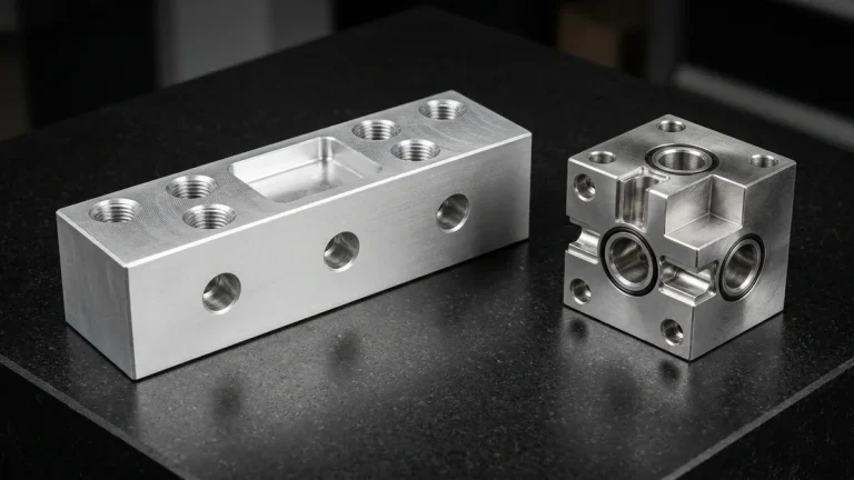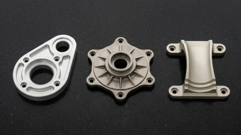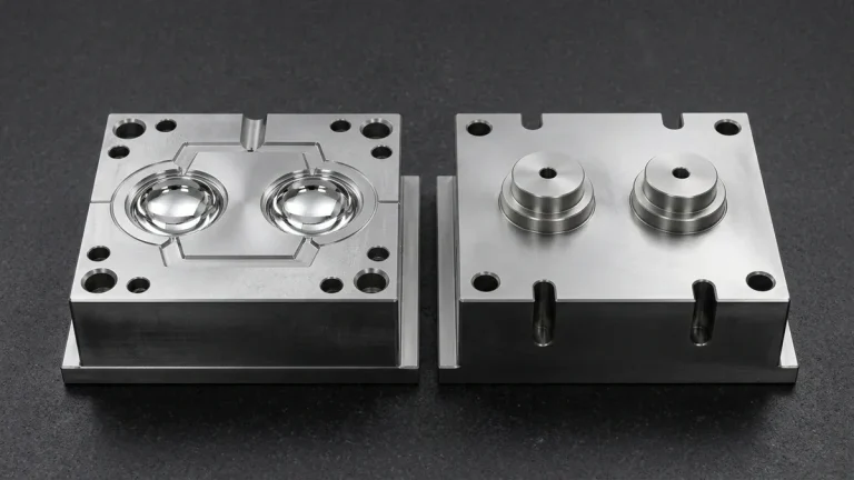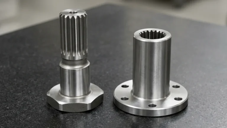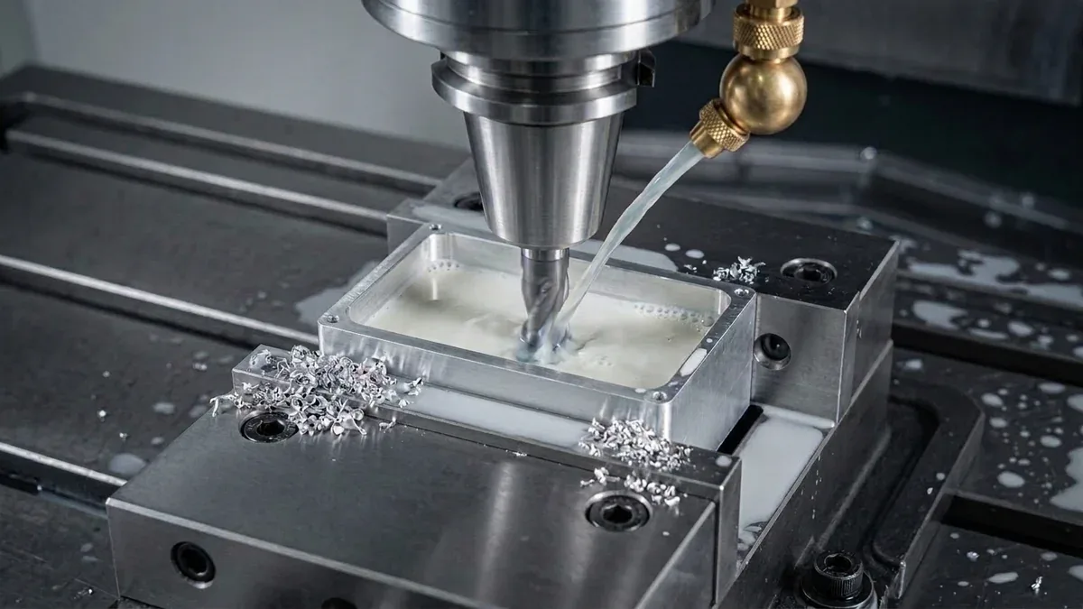
In computer numerical control (CNC) manufacturing, few parameters exert as profound an influence across part precision, surface integrity (Ra), cycle economics, and cutter longevity as spindle speed. Measured in revolutions per minute (RPM), spindle speed governs the fundamental mechanics of shear zone deformation, thermal dissipation, and cutting edge contact dynamics.
Yet, treating spindle speed merely as a dial to turn up for speed or down for tool safety represents an oversimplified approach that compromises both tolerance margins and production profitability. In precision manufacturing, mastering spindle speed in cnc machining ensures repeatable dimensional stability and predictable production scaling.
At AS Prototypes, our CNC engineering teams approach rotational dynamics through the rigorous lens of cutting mechanics, thermal partitioning, and modal vibration physics. Whether machining flight-critical 6061-T6 aluminum avionics enclosures at 24,000 RPM or turning tough Ti-6Al-4V titanium medical implants at controlled surface velocities, mastering spindle speed is essential to consistently delivering tight tolerances of ±0.010 mm to ±0.020 mm on critical milled and turned features (and ±0.005 mm via precision grinding or Wire EDM).
In this technical engineering guide, we unpack the mathematical foundations of spindle speed, examine Taylor’s tool life wear models, analyze machine spindle torque-power curves, demonstrate stability lobe chatter suppression, and share real-world manufacturing benchmarks across precision engineering alloys.
- 1. The Physics of Spindle Speed: RPM vs. Surface Cutting Speed (Vc)
- 2. Thermal Partitioning and Taylor’s Tool Life Equation
- 3. Spindle Motor Dynamics: Constant Torque vs. Constant Power Curves
- 4. Vibration Harmonics, Stability Lobes & Chatter Mitigation
- 5. Engineering Reference Matrix: Spindle Speed & Cutting Velocity Across Materials
- 6. Engineering Case Study: Eliminating Harmonic Resonance in Thin-Wall Avionics Housings
- 7. Practical Machinists’ Troubleshooting Rules for Spindle Speed
- 8. Technical Engineering FAQ
1. The Physics of Spindle Speed: RPM vs. Surface Cutting Speed (Vc)
To optimize subtractive machining, one must clearly differentiate between Spindle Speed (N) and Surface Cutting Speed (Vc). While spindle speed measures the angular rotational rate of the machine spindle, surface cutting speed represents the linear peripheral velocity at which the cutting edge travels across the material surface:
N = (1000 · Vc) / (π · D)
Where:
• N = Spindle Speed (Revolutions Per Minute, RPM)
• Vc = Surface Cutting Speed (meters per minute, m/min)
• D = Effective Cutting Tool Diameter (in milling) or Workpiece Diameter (in turning) (mm)
• 1000 = Conversion factor from millimeters to meters
In Imperial manufacturing shops utilizing Surface Feet per Minute (SFM), the corresponding formula is expressed as:
N = (12 · SFM) / (π · Dinch) ≈ (3.82 · SFM) / (Dinch)
The Kinematic Consequence of Diameter Variance
The inverse mathematical relationship between tool diameter (D) and rotational speed (N) dictates that to maintain an optimal linear cutting speed (Vc), smaller tools must spin vastly faster than larger cutters. For example, roughing a 6061-T6 aluminum pocket at Vc = 450 m/min with a Ø 20 mm carbide indexable end mill requires:
N = (1000 × 450) / (π × 20) ≈ 7,162 RPM
Conversely, executing micro-milling details on the same component using a Ø 1 mm solid carbide end mill at the identical surface speed would theoretically require:
N = (1000 × 450) / (π × 1) ≈ 143,239 RPM
Because physical machine tool spindles have defined maximum mechanical limits (typically 12,000 to 30,000 RPM in precision machining centers), micro-tools are often forced to operate below their ideal Vc, placing increased reliance on precise chip load control (fz) to prevent tool rubbing and edge premature fracture.
2. Thermal Partitioning and Taylor’s Tool Life Equation
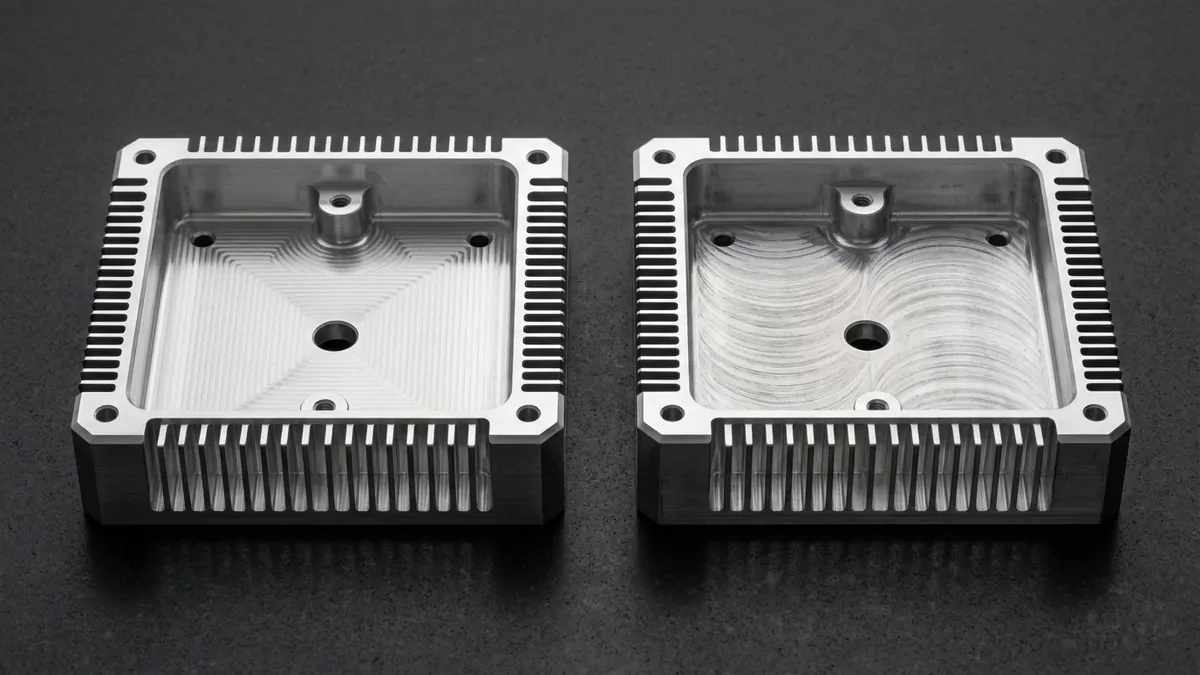
The primary constraint on spindle speed is thermal generation. During orthogonal cutting, mechanical shear energy converts almost entirely into heat within three primary deformation zones: the primary shear plane, the tool-chip interface, and the flank wear land.
1. Chip Evacuation and Thermal Partitioning
In high-speed CNC milling (HSM), increasing cutting velocity shifts the thermal partition balance favorably: a dominant percentage of generated heat (often 75% to 85%) is absorbed by the evacuated chip and expelled from the cut before conducting into the workpiece or cutting edge.
However, if the spindle speed exceeds the thermal threshold of the tool substrate or coating, temperature at the cutting tip surges past 900°C to 1100°C, triggering rapid crater wear, cobalt binder leaching, and plastic deformation of the carbide.
2. Taylor’s Tool Life Law
The profound sensitivity of tool longevity to cutting speed was mathematically codified by F.W. Taylor through the seminal empirical relation:
Where:
• Vc = Surface cutting speed (m/min)
• T = Tool life in minutes until flank wear (VB) reaches critical threshold (e.g., VB = 0.3 mm)
• n = Taylor exponent depending on tool material (n ≈ 0.10–0.15 for HSS; n ≈ 0.25–0.40 for cemented carbide; n ≈ 0.50–0.70 for ceramics and PCD)
• C = Constant corresponding to cutting speed for a 1-minute tool life
Because the exponent n in carbide milling is typically around 0.30, a modest 20% increase in spindle speed beyond the recommended envelope can slash cutter life by more than 50%. Conversely, operating significantly below recommended speed induces rubbing, work hardening on austenitic alloys, and built-up edge (BUE) formation, which tears the workpiece surface and fractures cutting edges.
3. Spindle Motor Dynamics: Constant Torque vs. Constant Power Curves
A frequent error among programming engineers is assuming that a machine tool’s advertised peak horsepower or kilowatt rating is available across all spindle speeds. In reality, industrial CNC machine spindles (whether belt-driven, gear-driven, or direct motorized spindles) operate under two distinct electromechanical power delivery regimes separated by the Base Speed (Nbase):
- Constant Torque Region (0 ≤ N < Nbase): Below base speed (typically 1,500 to 3,500 RPM on general-purpose machining centers), motor torque remains at its maximum peak value (Tmax), while available horsepower scales linearly with RPM (P = T · N / 9550). At very low RPM, available spindle power is severely constrained, making heavy large-diameter facing cuts vulnerable to spindle motor stall.
- Constant Power Region (Nbase ≤ N < Nmax): Once the spindle reaches base speed, the electrical inverter enters field weakening. Power reaches its rated maximum capacity (Pmax), while delivered torque drops inversely with RPM (T ∝ 1 / N). High-speed milling spindles running at 18,000 to 24,000 RPM operate in this high-power, low-torque zone, making them exceptionally fast for light-radial dynamic milling with small-to-medium tools, but incapable of driving large heavy-duty indexable shell mills.
At AS Prototypes, our process engineers map CAM toolpaths directly against our 3-axis and 5-axis machines’ spindle power curves, matching tooling engagement parameters to peak spindle operating efficiency.
4. Vibration Harmonics, Stability Lobes & Chatter Mitigation
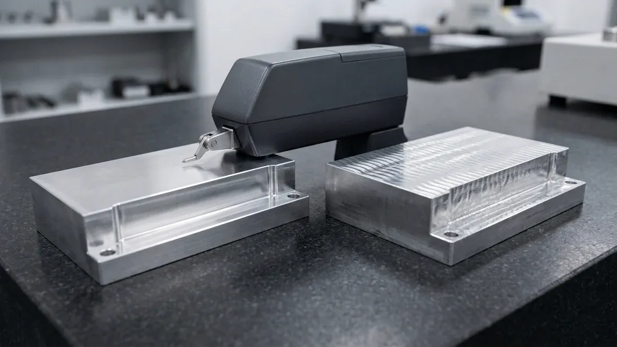
One of the most complex phenomena in precision CNC machining is regenerative chatter—a self-excited harmonic vibration that occurs when the cutting teeth engage the wavy undulations left on the workpiece surface by previous tooth passes. Left unchecked, chatter destroys surface finish (Ra > 3.2 μm), shatters carbide flutes, and causes severe spindle bearing brinelling.
Stability Lobe Diagrams (SLD)
Intuition often tempts operators to reduce spindle speed whenever chatter shrieks emerge. However, cutting physics reveals that stability is cyclical. A Stability Lobe Diagram maps the boundary between stable and unstable cuts as a function of spindle speed (N, x-axis) and axial depth of cut (ap, y-axis).
The fundamental stability peaks occur when the tooth passing frequency (ftooth) matches or phase-locks with the natural modal frequency of the tool-spindle-machine assembly (fn):
Where:
• ftooth = Tooth passing excitation frequency (Hz)
• N = Spindle speed (RPM)
• z = Number of cutting flutes
Inside the “stability lobe pockets,” an engineer can actually increase spindle speed into an upper harmonic pocket, allowing dramatically larger depths of cut (ap) with zero vibration and mirror-like surface finishes. At AS Prototypes, we utilize modal tap testing (impulse hammer excitation and accelerometer response) to mathematically identify resonance nodes on long-overhang and thin-wall setups.
Spindle Speed Variation (SSV)
In turning and deep-hole boring operations where structural damping is limited, CNC controllers equipped with Spindle Speed Variation (SSV) dynamically modulate rotational speed around a mean RPM (e.g., ±10% at a cyclic frequency of 1–2 Hz). This continuous phase perturbation prevents the cutting edge from synchronizing with surface waviness, breaking the regenerative feedback loop and eliminating chatter in tough aerospace alloys.
5. Engineering Reference Matrix: Spindle Speed & Cutting Velocity Across Materials
The following engineering data matrix outlines baseline cutting velocities (Vc), calculated spindle speeds for a standard Ø 10 mm solid carbide end mill, and tooling recommendations across common engineering alloys and polymers:
| Workpiece Material | Material State | Target Vc (m/min) | Spindle RPM (Ø 10mm) | Recommended Tooling & Coating | Coolant Strategy |
|---|---|---|---|---|---|
| Aluminum 6061-T6 | Solution Heat-Treated | 350 – 750 | 11,140 – 23,870 | 3-Flute Uncoated / DLC Polished Carbide | High-Pressure Flood (8–10% Emulsion) |
| Aluminum 7075-T6 | High-Strength Aerospace | 300 – 600 | 9,550 – 19,100 | 3-Flute ZrN / TiB2 Coated Carbide | Flood Coolant / Through-Spindle Air |
| Stainless Steel 304 / 316L | Austenitic (Work Hardening) | 90 – 160 | 2,860 – 5,090 | 4-Flute AlTiN / AlCrN Variable Helix | High-Pressure Flood (Maintain Positive Chip Load) |
| Titanium Ti-6Al-4V (Grade 5) | Annealed Aerospace / Medical | 45 – 85 | 1,430 – 2,700 | 5-Flute TiAlSiN Nano-Composite Carbide | High-Pressure Through-Spindle (70 Bar+) |
| Inconel 718 | Nickel-Chromium Superalloy | 20 – 45 | 640 – 1,430 | Micro-Grain Carbide (AlTiN) or Solid Ceramic | Flood for Carbide; High-Speed Air Blast for Ceramics |
| Pre-Hardened Steel (NAK80 / P20) | 38 – 42 HRC Mold Steel | 120 – 220 | 3,820 – 7,000 | 4-Flute TiSiN Hard-Coated End Mill | Air Blast / Minimum Quantity Lubrication (MQL) |
| PEEK / POM-C (Delrin) | High-Performance Engineering Polymer | 250 – 500 | 7,960 – 15,910 | 1-to-2 Flute Razor-Sharp High-Rake Carbide | Chilled Compressed Air (Avoid Thermal Recasting) |
6. Engineering Case Study: Eliminating Harmonic Resonance in Thin-Wall Avionics Housings
An aerospace customer contracted AS Prototypes to manufacture a series of lightweight 6061-T6 aluminum drone communication chassis featuring 0.8 mm thin vertical ribs and deep pockets (42 mm depth). Initial trials executed by the client’s internal shop ran into severe harmonic chatter:
- Initial Client Setup: Ø 10 mm 3-flute end mill running at standard 12,000 RPM (Vc ≈ 377 m/min) with an axial depth of cut (ap) of only 1.2 mm due to violent chatter resonance. Surface finish measured an unacceptable Ra = 3.6 μm with visible cyclic chatter faceting.
- Harmonic Analysis: Our engineering team mounted an accelerometer on the spindle housing and performed modal tap testing, identifying a high-dynamic compliance resonance node at 1,220 Hz. At 12,000 RPM with 3 flutes, the excitation frequency (ftooth = 12000 × 3 / 60 = 600 Hz) established an out-of-phase regenerative wave that amplified rib deflection.
- The High-Speed Lobe Solution: Utilizing the calculated Stability Lobe Diagram, our programmers shifted the spindle speed upward into a stable harmonic sweet spot at 18,300 RPM (ftooth = 915 Hz, aligning precisely with a stable vibration antinode). Simultaneously, we transitioned to an unequal-helix 3-flute polished carbide end mill and increased the axial depth of cut to a full 4.5 mm using dynamic trochoidal milling toolpaths.
- The Results:
- Cutting vibration amplitude plunged by 84%;
- Overall roughing and finishing cycle time decreased by 58%;
- Final wall thickness tolerance held within ±0.012 mm with a mirror finish of Ra = 0.32 μm directly off the machine, eliminating secondary manual benching.
7. Practical Machinists’ Troubleshooting Rules for Spindle Speed
When dialing in new CNC programs or diagnosing unstable cutting conditions on the shop floor, our senior machinists employ the following diagnostic protocols:
- High-Pitched Squeal vs. Low-Frequency Rumble: High-frequency squeal generally indicates tool-tip or thin-wall harmonic chatter, which can often be silenced by shifting spindle speed up or down by 8% to 15% into a stable lobe. A low-frequency dull rumble indicates whole-machine or fixture compliance flex, requiring reduced depth of cut (ap) or beefed-up workpiece clamping.
- Built-Up Edge (BUE) on Flutes: If ductile aluminum or low-carbon steel is welding itself to the cutter face, your surface speed (Vc) is too low. Accelerating the spindle raises interface temperature enough to promote clean shear flow and prevent adhesion.
- Thermal Discoloration on Steel Chips: When milling steels with coated carbide, straw or deep blue chips indicate healthy thermal extraction into the chip. If chips are bright white and the tool edge shows rapid micro-chipping, surface speed is too low. If chips turn dark purple-black and flank wear progresses rapidly, spindle speed is excessive.
- Feed Rate Synchronization (F = N · fz · z): Never adjust spindle speed in isolation without recalculating linear feed rate (F). Increasing RPM while keeping linear feed fixed reduces chip load per tooth (fz), risking cutter rubbing, friction heat, and catastrophic thermal breakdown.
8. Technical Engineering FAQ
Linear table feed rate (Vf, in mm/min or IPM) is directly coupled to spindle speed (N, in RPM), number of cutter flutes (z), and chip load per tooth (fz): Vf = N × z × fz. If an operator changes spindle speed without proportionally adjusting the linear feed rate, the uncut chip thickness per tooth changes, risking either tool rubbing (if chip load drops below the cutting edge radius) or edge chipping (if chip load spikes).
Regenerative chatter occurs when the tooth-passing excitation frequency (f_tooth = N × z / 60) clashes with the natural structural resonance of the tool-spindle assembly. At high spindle speeds, stability lobe diagrams (SLD) reveal wide ‘stability pockets’ where the tooth-passing frequency synchronizes in phase with the dominant vibration mode, allowing deeper axial cuts at a slightly higher RPM without regenerative oscillation.
In CNC turning and facing, Constant Surface Speed (G96) dynamically increases spindle RPM as the lathe tool feeds radially toward the centerline (D → 0) so the cutting velocity remains uniform across the entire face. Because theoretical RPM approaches infinity as diameter approaches zero, programmers pair G96 with a G50 maximum spindle speed clamp (e.g., G50 S3500) to prevent dangerous chuck centrifugal loss at the center.
At sustained high speeds (18,000 to 24,000 RPM), bearing friction and motor stator heat cause the steel spindle shaft to expand axially by 0.015 to 0.035 mm unless actively managed. Precision machining centers counteract this drift using chilled dielectric jacket oil circulation, ceramic hybrid angular-contact bearings (Si3N4), and closed-loop laser or tactile tool-setter probing cycles prior to finishing passes.
Partner with Our Precision CNC Machining & Engineering Team
Eliminate tool deflection, residual stress distortion, and tolerance stack-up risks before production begins. Upload your 3D CAD files (STEP/IGES) and 2D GD&T drawings for a comprehensive shop-floor DFM review and custom quotation.
Upload 3D CAD for Engineering DFM & RFQ