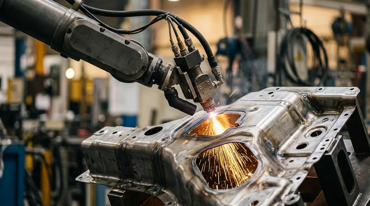
Modern vehicle architectures rely on precision automotive sheet metal fabrication to balance crashworthiness, torsional chassis rigidity, and Electric Vehicle (EV) mass reduction. From high-strength low-alloy (HSLA) suspension brackets and galvanized Body-in-White (BIW) gussets to aluminum battery cooling trays, formed sheet metal constitutes over 60% of vehicle curb weight.
Selecting the optimal forming route balances non-recurring engineering (NRE) tooling investment against cycle time, work-hardening behavior, and elastic springback recovery. While high-volume programs amortize hardened progressive stamping dies across hundreds of thousands of strokes, EVT/DVT prototypes and specialty EV builds utilize fiber laser cutting, CNC press brake bending, or hydroforming.
At our in-house sheet metal and stamping die facility, we process standard mill-stock automotive steels and aluminums from 0.8 mm to 6.0 mm (0.031″ to 0.236″) gauge. Whether you need rapid precision sheet metal fabrication or hard-tooled custom automotive manufacturing parts, this guide covers forming pathways, springback, and DFM rules.
Executive Summary & Engineering Takeaways (BLUF)
- Volume Pathways: Use laser cutting + CNC press brake bending for 1–500 units (zero tooling NRE), hydroforming for 100–5,000 shells (50%–65% lower tooling NRE), and progressive stamping for 10,000–500,000+ brackets.
- Forming Tolerances: Fiber laser cutting holds ±0.05 to ±0.10 mm (±0.002″ to ±0.004″); single-flange press brake bending achieves ±0.20 to ±0.30 mm (±0.008″ to ±0.012″) and ±0.5° to ±1.0° per DIN 6935 / ISO 2768-mK.
- HSLA Springback & EV Alloys: HC340LA / HC420LA / QSTE420TM and DP590 / DP780 / DP980 steels require 4° to 12° over-bending and corner gussets; 5052-H32 / 5754-H22 (Rin ≥ 1.0t–1.5t) is the primary alloy for cold-bent EV battery trays over brittle 6061-T6 (3.0t–6.0t).
- Fixture Metrology: Stampings are verified via 2.5D Optical Vision Measurement Systems (VMS), dedicated checking fixtures with 3.0 mm feeler gaps, 0.05–0.50 mm feeler gauges, and Go/No-Go flush pins, mating assembly fit-up, Grade 00 knife-edge straightedges, bevel protractors (±0.5°), and 3.5–6.0 bar leak testing.
- Ex-Factory Lead Times: Bare laser-brake parts ship in 4 to 8 business days (7 to 12 business days coated), production runs take 7 to 30 business days, and D2 / SKD11 / Cr12MoV progressive dies take 18 to 35 business days.
Article Engineering Navigation
- 1. How Do Laser Cutting, Hydroforming & Progressive Stamping Compare?
- 2. How Do CNC Press Brakes Compensate for HSLA & Dual-Phase Springback?
- 3. Which Automotive Sheet Metal Alloys & Metric Gauges Are Stocked In-House?
- 4. How Are EV Battery Trays, Gussets & PEM Fasteners Integrated?
- 5. What Are the Critical DFM Rules for Automotive Sheet Metal Stampings?
- 6. How Are Automotive Stampings Inspected, Coated & Delivered?
- 7. Technical Engineering FAQ
1. How Do Laser Cutting, Hydroforming & Progressive Stamping Compare?
For low-volume batches of 1 to 500 units, Agile Fiber Laser Cutting + CNC Press Brake Bending requires zero hard tooling NRE. Nitrogen fiber lasers cut flat blanks to ±0.05 to ±0.10 mm (±0.002″ to ±0.004″) accuracy, while CNC press brakes form flanges to ±0.20 to ±0.30 mm and ±0.5° to ±1.0° per DIN 6935 and ISO 2768-mK.
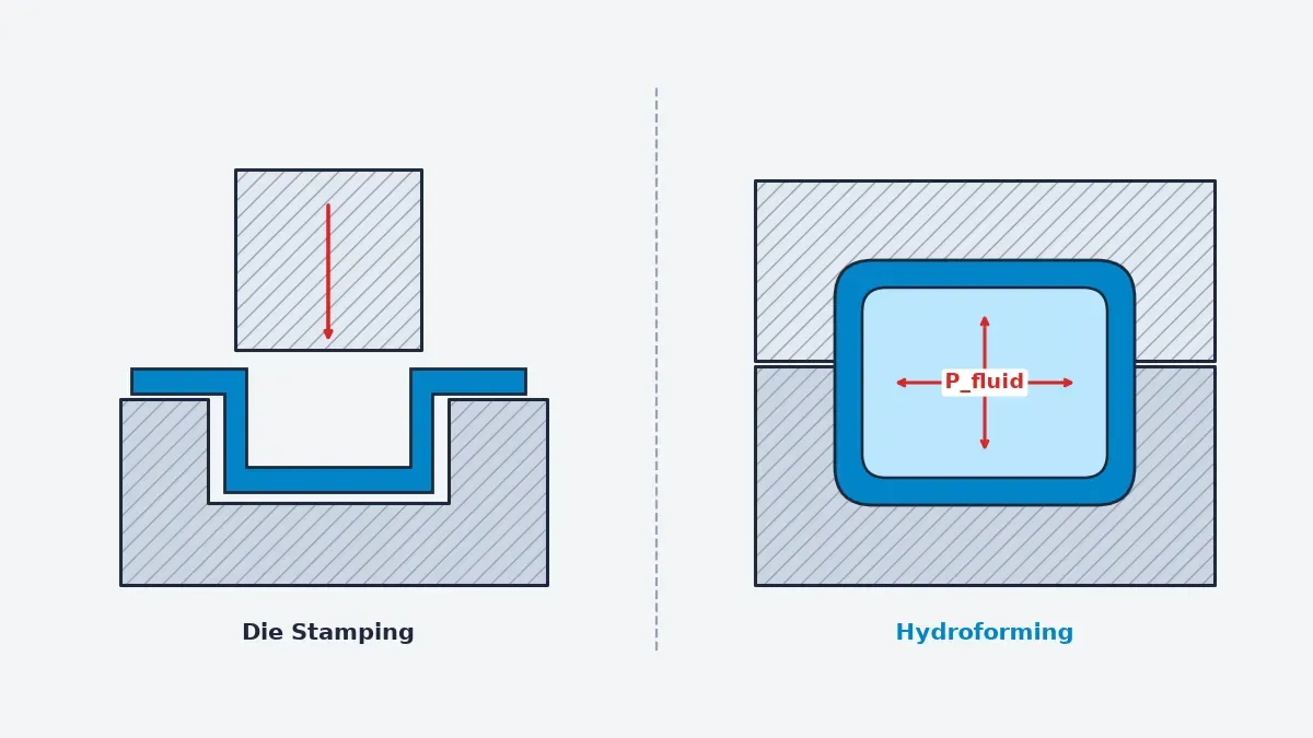
For bridge runs of 100 to 5,000 units, Sheet & Tube Hydroforming applies 100 to 400 MPa (14.5 to 58.0 ksi) hydraulic fluid pressure to form sheet or tubular stock inside a split or single die cavity. Eliminating matched opposing punches cuts tooling NRE by 50% to 65% and limits wall thinning below 8% to 12% across complex subframes.
For mass production of 10,000 to 500,000+ units, Progressive & Transfer Die Stamping feeds coil strip through multi-station hardened D2, SKD11, or Cr12MoV dies (58–62 HRC per ASTM E18). Running at 30 to 120 strokes/min, progressive dies execute piercing, coining, embossing, and drawing in one continuous stroke, delivering T1 samples in 18 to 35 business days.
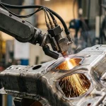
During EVT/DVT validation builds, we also pair stage-die drawing with 6-axis robotic fiber laser trimming for rapid aperture revisions. As illustrated below, comparing vertical punch-and-die stamping against internal fluid hydroforming (Pfluid = 100–400 MPa) clarifies how tooling architecture governs wall thinning, stroke speed, and NRE investment.
| Pathway | Economic Volume | Tooling NRE | Tolerance & Speed | Ex-Factory Lead Time | Automotive Applications |
|---|---|---|---|---|---|
| Laser + Press Brake | 1–500 pcs | Zero Hard Tooling NRE | Laser ±0.05–0.10 mm; Bend ±0.20–0.30 mm, ±0.5°–1.0° | 4–8 days bare; 7–12 days coated | EV battery brackets, inverter mounts |
| Sheet / Tube Hydroforming | 100–5,000 pcs | Single/Split Cavity (50%–65% Lower NRE) | 100–400 MPa fluid; Thinning < 8%–12% | 18–30 business days (tool & T1) | Exhaust heat shields, subframe tubes, B-pillars |
| Hybrid Draw + Laser Trim | 200–3,000 pcs | Stage Draw Die Only (No Trim/Pierce Dies) | Trim ±0.15 mm via 6-axis robotic fiber laser | 18–28 business days (stage die & trim) | EVT/DVT subframes, shock towers, crossmembers |
| Progressive Stamping | 10,000–500,000+ | Hardened D2 / SKD11 / Cr12MoV Die (58–62 HRC) | ±0.05–0.15 mm; 30–120 strokes/min | 18–35 business days (25–35 multi-station die & T1) | Chassis gussets, crash boxes, seat tracks, busbars |
2. How Do CNC Press Brakes Compensate for HSLA & Dual-Phase Springback?
Forming HC340LA / HC420LA / Q355B and DP600 / DP800 steels causes elastic recovery upon punch retraction. Governed by Δθ ÷ θ ∝ (σy ÷ E) × (Rin ÷ t) (E = 210,000 MPa for steel vs. 70,000 MPa for aluminum), flanges spring open 3°–7° in HSLA/DP600 and 7°–12° in DP800/DP980 versus 1°–2° in SPCC.
In CNC air bending, the inside bend radius (Rin) is governed primarily by the lower V-die opening (V) rather than the punch tip radius. Selecting V = 8t to 10t for HSLA steels produces a natural air-bent radius of Rin = 1.5t to 2.0t (≈ 0.16V to 0.20V) while keeping press-brake tonnage within safe tooling limits.
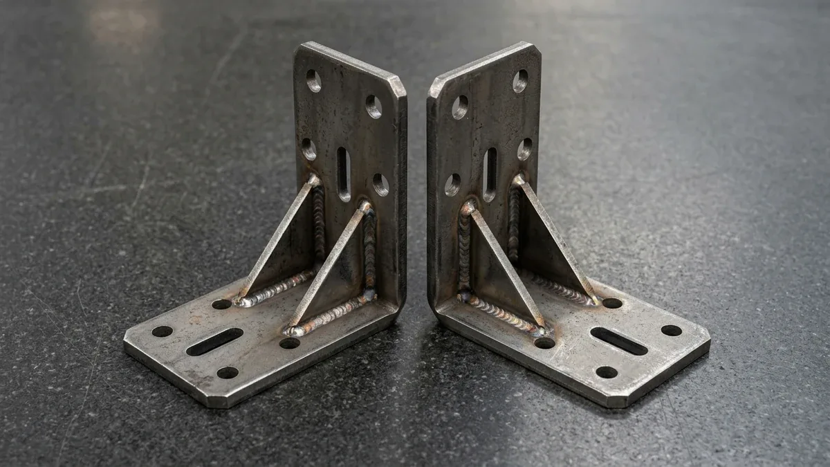
Our press brake engineers counteract springback through three shop-floor controls: programming acute 78° to 86° punches in V = 8t to 10t dies for 4° to 7° over-bending, bottom coining the bend apex, and welding triangular steel corner gusset plates with stacked-dime TIG fillet beads across open-ended 4.0 mm (0.157″) HC420LA 90° L-bracket flanges.
📐 Shop-Floor Formulas: DIN 6935 Bend Deduction, Air-Bend Tonnage & Blank Shear Force
BA = π × (θ ÷ 180°) × (Rin + K × t) | OSSB = tan(θ ÷ 2) × (Rin + t) | BD = 2 × OSSB − BA
Fbend = [1.42 × UTS × t2 × L] ÷ (1,000 × V) | Fshear = [Pperim × t × τshear] ÷ 1,000 | Δθ = 1.75 × θ × (UTS ÷ E) × (V ÷ t)
Worked Example 1 — DIN 6935 Flat Pattern (2.5 mm HC420LA): For t = 2.5 mm, θ = 90°, Rin = 3.75 mm (1.5t), and K = 0.44: BA = 7.62 mm (0.300″), OSSB = 6.25 mm (0.246″), BD = 4.88 mm (0.192″), and Lflat = 200 − 2(4.88) = 190.24 mm (50×100×50 mm U-channel).
Worked Example 2 — 2.5 mm Tonnage, Shear & Springback: With UTS = 520 MPa, E = 210,000 MPa, τshear = 0.80·UTS = 416.0 MPa, L = 180 mm, V = 20 mm (8t), and Pperim = 600 mm: Fbend = 41.54 kN (4.24 tf), Fshear = 624.0 kN (63.63 tf, 110T press), and Δθ = 3.12° (86.88° overbend).
Worked Example 3 — DIN 6935 Unfolding (3.0 mm Q355B / HC340LA): For T=3.0 mm, 90° bend, V=24 mm, Rin=4.5 mm, K=0.44, L1=80.0 mm, and L2=60.0 mm: BA = 9.142 mm, OSSB = 7.500 mm, BD = 15.000 − 9.142 = 5.858 mm, and Lflat = 80 + 60 − 5.858 = 134.142 mm.
Worked Example 4 — 3.0 mm & 4.0 mm HSLA Air-Bending Tonnage (UTS = 520 MPa): For T=3.0 mm, L=500 mm, and V=24 mm, Fbend = 138.45 kN ≈ 138.4 kN (14.1 tf); for t=4.0 mm, L=600 mm, and V=32 mm, Fbend = 221.52 kN (22.6 tf / 24.9 US tons).
3. Which Automotive Sheet Metal Alloys & Metric Gauges Are Stocked In-House?
Specifying non-standard Imperial sheet thicknesses creates unnecessary mill delays. Our in-house material warehouse stocks standard metric gauges of 0.8, 1.0, 1.2, 1.5, 2.0, 2.5, 3.0, 4.0, 5.0, and 6.0 mm (0.031″ to 0.236″) with uniform wall thickness (tinner = touter) across automotive steels and aluminums.
Cold-rolled DC01/SPCC (0.8–2.5 mm), galvanized DX51D+Z/SGCC/SECC (0.8–3.0 mm), and hot-rolled SPHC/Q235B (1.5–6.0 mm) serve cabin brackets and floor pans. Structural chassis mounts use HC340LA/HC420LA/Q355B (1.5–6.0 mm, Yield 340–500 MPa), DP590/DP600/DP800 (1.2–3.0 mm, Yield 350–550+ MPa) reinforces B-pillars, and 304/409L stainless steel (0.8–3.0 mm) forms exhaust heat shields.
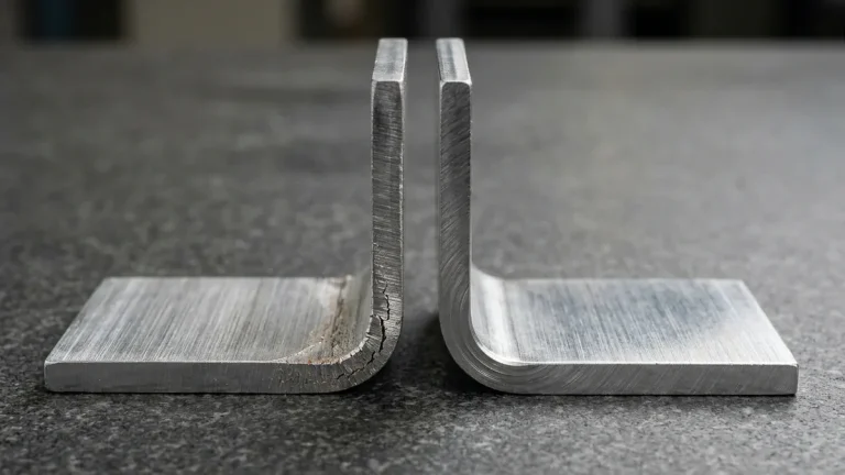
For cold-bent EV battery enclosure lids, cooling shrouds, and busbar covers, strain-hardened 5052-H32 / 5754-H22 (1.5–4.0 mm, Rin ≥ 1.0t–1.5t) is the primary alloy. Conversely, 6061-T6 cracks along outer fibers at 1.0t–2.0t, requires Rin ≥ 3.0t–6.0t for cold bending, and suffers severe heat-affected zone (HAZ) softening after TIG or laser welding.
Coil rolling grain direction critically impacts formability in HC340LA / HC420LA, DP590 / DP780, and aluminum sheets. Whenever possible, our CAM engineers nest laser blanks so primary bend lines run transverse (perpendicular, 90°) to the coil rolling grain, preventing outer-fiber splitting along elongated sulfide or intermetallic inclusions.
| Alloy Grade | Standard Gauges (mm) | Yield / UTS (MPa) | Min. Radius (Rin) | Springback / Over-Bend | Automotive Applications |
|---|---|---|---|---|---|
| DC01 / DC04 (SPCC / SPCE) | 0.8–2.5 | Yield 140–240; UTS 270–410 | ≥ 0.5t–0.8t | 1°–2° | Deep-drawn cabin & ECU brackets |
| DX51D+Z / SGCC / SECC Galvanized | 0.8–3.0 | Yield 180–300; UTS 290–430 | ≥ 1.0t | 1.5°–2.5° | Floor pans, wheel-arch hat-channel gussets |
| HC340LA / HC420LA / Q355B (SPHC / Q235B) | 1.5–6.0 | Yield 340–500; UTS 420–620 | ≥ 1.5t–2.0t (V = 8t–10t) | 3°–7° over-bend | Suspension control-arm L-brackets, chassis mounts |
| DP590 / DP600 / DP780 / DP800 / DP980 | 1.2–3.0 | Yield 350–700 (DP600/800: 380–550); UTS 590–1,050 | ≥ 2.0t–3.0t | 3°–7° (DP600); 7°–12° (DP800+) | B-pillars, crash boxes, rocker reinforcements |
| 5052-H32 / 5754-H22 Al (Workhorse) | 1.5–4.0 | Yield 193–215; UTS 228–280 | ≥ 1.0t–1.5t | 2°–3.5° | Cold-bent EV battery enclosure lids, shrouds, busbar covers |
| 6061-T6 Aluminum (Cracks at 1.0t–2.0t) | 1.5–6.0 | Yield 276; UTS 310+ (HAZ Softens) | ≥ 3.0t–6.0t | 3°–5.5° | Flat CNC-machined baseplates, unbent skid plates |
| SUS304 / SUH409L Stainless Steel | 0.8–3.0 | Yield 205–260; UTS 420–560 | ≥ 1.0t–1.5t | 2°–4° | Exhaust heat shields, muffler baffles, EGR brackets |
4. How Are EV Battery Trays, Gussets & PEM Fasteners Integrated?
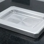
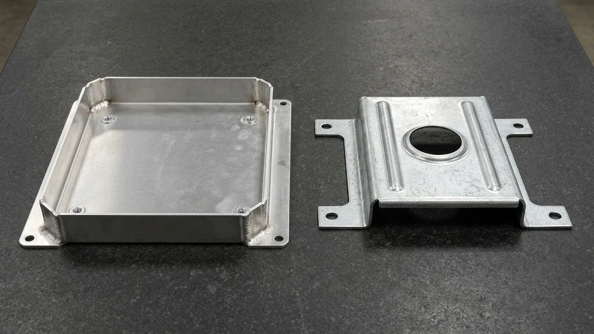
EV skateboard platforms pair fabricated aluminum enclosures with stamped steel gussets, joined via precision TIG, pulsed MIG, or handheld and robotic fiber laser welding. Shown below, the 2.5 mm (0.098″) 5052-H32 aluminum EV battery tray (left) combines fiber laser cutting, CNC press brake flanges, corner bend reliefs, stacked-dime TIG corner welds, and pressed PEM self-clinching nuts.
Alongside it, the 2.5 mm (0.098″) galvanized HSLA steel hat-channel chassis crossmember bracket (right) is produced via progressive die stamping at 60 strokes/min, incorporating a central flanged lightening hole, parallel embossed stiffening beads, and pierced corner mounting holes. For PEM hardware, laser-cut pilot holes hold +0.08 / −0.00 mm (+0.003″ / −0.000″) before hydro-pneumatic squeezing.
Integrating self-clinching nuts (PEM CLS / S series), studs (FH series), and standoffs (BSO series) into the 5052-H32 tray alongside the stamped HSLA hat-channel crossmember bracket eliminates loose pack hardware. Host sheets must remain at least 20 HRC softer than the fastener so the serrated ring cold-flows parent metal cleanly.
| Joining Method | Compatible Alloys & Gauges | Thermal Distortion / HAZ | Joint Integrity & Strength | Automotive Use Cases |
|---|---|---|---|---|
| AC/DC Pulsed TIG (GTAW) | 5052 / 5754 Al (1.5–4.0 mm); HC420LA (1.5–6.0 mm) | Moderate (3.0–5.0 mm HAZ width) | IP67/IP68 leak-tight stacked-dime fillet | EV battery tray corners, L-bracket gussets |
| Fiber Laser Welding | DC01, DX51D+Z, HC420LA, 5052 Al (0.8–4.0 mm) | Ultra-Low (0.5–1.2 mm HAZ; 3×–4× faster) | Deep keyhole penetration; minimal warpage | Battery cooling shrouds, thin BIW enclosures |
| Resistance Spot Welding (RSW) | DC01, SGCC, HC420LA, DP590 (0.8–3.0 mm lap) | Localized Nugget (⌀4.0–6.0 mm ≈ 5√t) | High lap-shear strength; 0.5–1.5 s/spot | Hat-channel crossmembers, floor gussets |
| PEM Self-Clinching Hardware | 5052 Al (≤ 50 HRB); DC01 / HC340LA (≤ 80 HRB) | Zero Thermal Input (Cold Hydro-Pneumatic Press) | High push-out & torque-out resistance | BMS PCB standoffs, M4–M8 lid grounding nuts |
- Nitrogen Fiber Laser Blank Cutting & Deburring: Cut the flat 5052-H32 blank with high-pressure nitrogen assist gas to prevent oxide scale, holding PEM mounting hole diameters within +0.08 / −0.00 mm (+0.003″ / −0.000″).
- Optical Flatness & Aperture Verification: Scan the deburred first-article 2D flat pattern on a 2.5D Optical Vision Measurement System (VMS) within ±0.05 to ±0.10 mm to confirm hole-to-bend tangent clearances before forming.
- Multi-Stage CNC Press Brake Forming: Form perimeter walls using optical laser angle measurement and acute punch compensation, ensuring corner tear-relief notches align cleanly for zero-gap weld fit-up.
- TIG / Laser Corner Seam Welding & Hydro-Pneumatic PEM Pressing: Seal-weld the four corner seams using AC pulsed TIG or fiber laser welding, press PEM self-clinching nuts flush, and verify 3.5–6.0 bar IP67 / IP68 seal integrity.
5. What Are the Critical DFM Rules for Automotive Sheet Metal Stampings?
Enforcing quantitative sheet metal DFM rules in 3D CAD prevents outer-fiber cracking, ovalized mounting holes, and press-brake V-die collision across both prototype and progressive stamping runs. Review these six critical geometric thresholds and the accompanying reference table before releasing flat DXF patterns and 3D STEP models to production:
- Inside Bend Radius (Rin): Specify Rin ≥ 0.5t–0.8t for DC01 / SPCC, 1.0t–1.5t for 5052-H32 / 5754-H22, 1.5t–2.0t for HC340LA / HC420LA, 2.0t–3.0t for DP590 / DP780, and 3.0t–6.0t for brittle 6061-T6.
- Hole-to-Bend Clearance (Dmin): Keep circular holes ≥ 2.0t + Rin and elongated slots ≥ 3.5t + Rin away from the bend tangent line to prevent plastic teardrop distortion.
- Minimum Flange Length & Tear Reliefs: Maintain flange length Lmin ≥ 4.0t + Rin to span the V-die shoulders, and size laser-cut bend-relief notches at width ≥ 1.0t (min 1.5 mm / 0.059″) and depth ≥ Rin + t.
- Minimum Pierced Hole Diameter: Keep stamped hole diameters dmin ≥ 1.2t in cold-rolled steels and ≥ 1.5t in HC420LA / DP590 to prevent slender carbide punch compressive buckling.
- PEM Fastener Edge Distance (Cmin): Position self-clinching nut and stud centerlines at least 1.5× the fastener shank diameter from any sheet edge or bend tangent so parent metal does not bulge outward.
- Embossed Stiffening Beads & Corner Gussets: Limit stamped bead depth to 1.5t–2.5t with ≥ 2.0t punch/die radii, or add TIG-welded triangular corner gusset plates on heavy 4.0–6.0 mm suspension brackets.
| DFM Feature | Design Formula / Threshold | 2.5 mm HC420LA Example (Rin = 3.75 mm) | Defect Prevented |
|---|---|---|---|
| Min. Inside Bend Radius | 1.0t–1.5t (5052); 1.5t–2.0t (HC420LA); 3.0t–6.0t (6061) | 2.5–3.75 mm (5052); 3.75–5.0 mm (HC420LA); 7.5–15.0 mm (6061) | Outer-fiber tensile necking & grain fracture |
| Hole-to-Bend Edge Distance | Dmin ≥ 2.0t + Rin (Holes); ≥ 3.5t + Rin (Slots) | ≥ 8.75 mm for holes; ≥ 12.50 mm for slots | Ovalized fastener holes & thread binding |
| Minimum Bent Flange Length | Lmin ≥ 4.0t + Rin | ≥ 13.75 mm outside flange leg | Sheet slipping into V-die cavity during stroke |
| Corner Bend Relief Notch | Width ≥ 1.0t (min 1.5 mm); Depth ≥ Rin + t | 2.5 mm wide × 6.25 mm deep relief slot | Corner tearing & overlapping flange interference |
| Stamped Pierced Hole Dia. | dmin ≥ 1.2t (DC01 / SPCC); ≥ 1.5t (HC420LA / DP590) | ⌀3.0 mm (DC01 / SPCC); ⌀3.75 mm (HC420LA) | SKD11/D2 piercing punch fatigue & snapping |
6. How Are Automotive Stampings Inspected, Coated & Delivered?
Because thin-walled sheet metal parts flex in a free state, we inspect 2D laser-cut flat blanks within ±0.05 to ±0.10 mm (±0.002″ to ±0.004″) on a non-contact 2.5D Optical Vision Measurement System (VMS). Every shipment includes full-dimensional First Article Inspection (FAI) and PPAP-style dimensional reports.
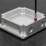
Formed 3D brackets, subframes, and enclosures are verified on dedicated automotive checking fixtures with 3.0 mm nominal gap blocks, 0.05–0.50 mm feeler gauges, and Go/No-Go flush pins, plus mating assembly fit-up. Inspectors also use Grade 00 knife-edge straightedges, bevel protractors (±0.5°), radius gauges, Class ZZ Go/No-Go pin and thread gauges, and 3.5–6.0 bar (50.8–87.0 PSI) leak testing.
For corrosion protection verified per ASTM B117 salt spray testing (240–720+ hours), steel brackets receive cathodic E-coat (15–25 µm / 0.6–1.0 mil), zinc-nickel plating, or powder coating, while aluminum EV trays receive MIL-A-8625 Type II anodizing or MIL-DTL-5541 chromate conversion. All schedules below reflect Ex-Factory Production & Inspection Turnaround, separate from 3 to 5 business days air transit:
- DFM & Quote: Within 24 hours (24 to 48 hours for progressive stamping dies).
- Bare Laser-Cut, Bent & Welded Prototypes: 4 to 8 business days ex-factory.
- Surface-Finished Prototypes (E-Coated, Anodized, Powder-Coated): 7 to 12 business days ex-factory.
- Low-to-Mid Volume Production (10 to 1,000+ units): 7 to 30 business days ex-factory.
- Progressive Stamping Dies & T1 Samples: 18 to 35 business days ex-factory.
🔗 Related Engineering Guides
7. Technical Engineering FAQ
Fiber laser cutting and CNC press brake bending suit 1 to 500 prototype units with zero tooling NRE and 4 to 8 business days turnaround. Above 10,000 units, hardened D2 or SKD11 progressive stamping dies running at 30 to 120 strokes/min deliver the lowest unit cost.
High-strength HC340LA, HC420LA, and DP590 to DP980 steels exhibit 4° to 12° elastic springback due to their elevated yield-to-modulus ratio. Our engineers compensate using 8t to 10t V-dies, acute 78° to 86° punches for overbending, bottom coining, and TIG-welded corner gussets to hold ±0.5° accuracy.
Precipitation-hardened 6061-T6 aluminum cracks along the outer fiber at 1.0t to 2.0t radii, requires 3.0t to 6.0t bends, and suffers weld HAZ softening. Strain-hardened 5052-H32 and 5754-H22 bend cleanly at 1.0t to 1.5t, resist road-salt corrosion, and support leak-tight TIG or laser welding.
We verify 2D laser-cut flat blanks within ±0.05 to ±0.10 mm on a 2.5D Optical Vision Measurement System (VMS). Formed 3D brackets and EV trays are validated using 3.0 mm feeler-gap checking fixtures, Go/No-Go flush pins, mating fit-up, bevel protractors, and 3.5–6.0 bar leak testing.
Ready to Validate Your Automotive Sheet Metal & Stamping Design?
Upload your 3D CAD models (STEP / IGES) and 2D drawings (DXF / PDF) for an engineering DFM review covering DIN 6935 bend radii, HSLA springback compensation, and progressive die layouts from our in-house sheet metal engineering team.
Upload 3D CAD for Automotive Sheet Metal DFM & Quote →