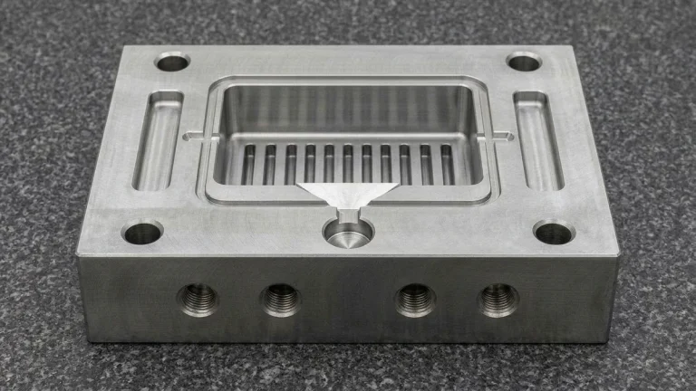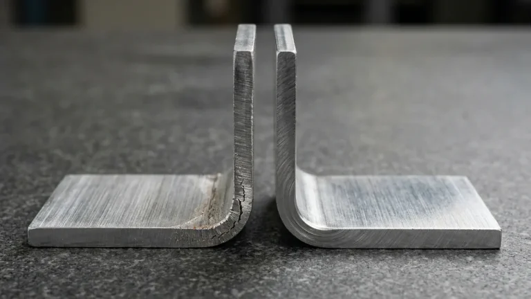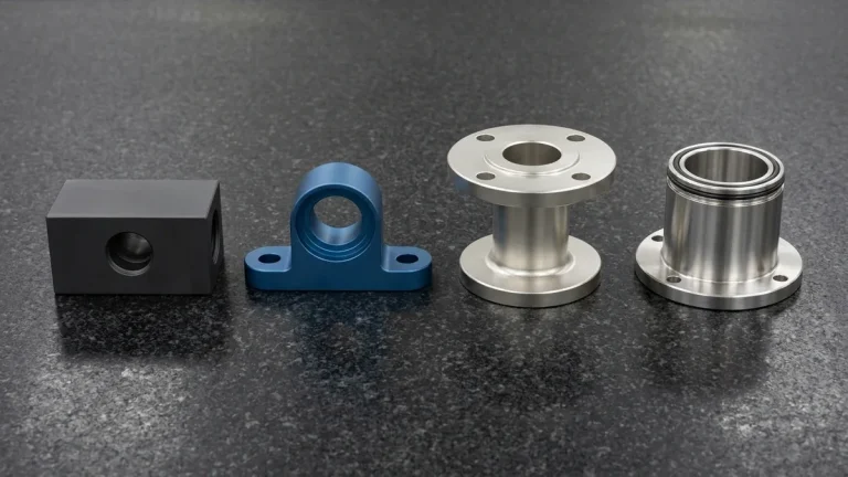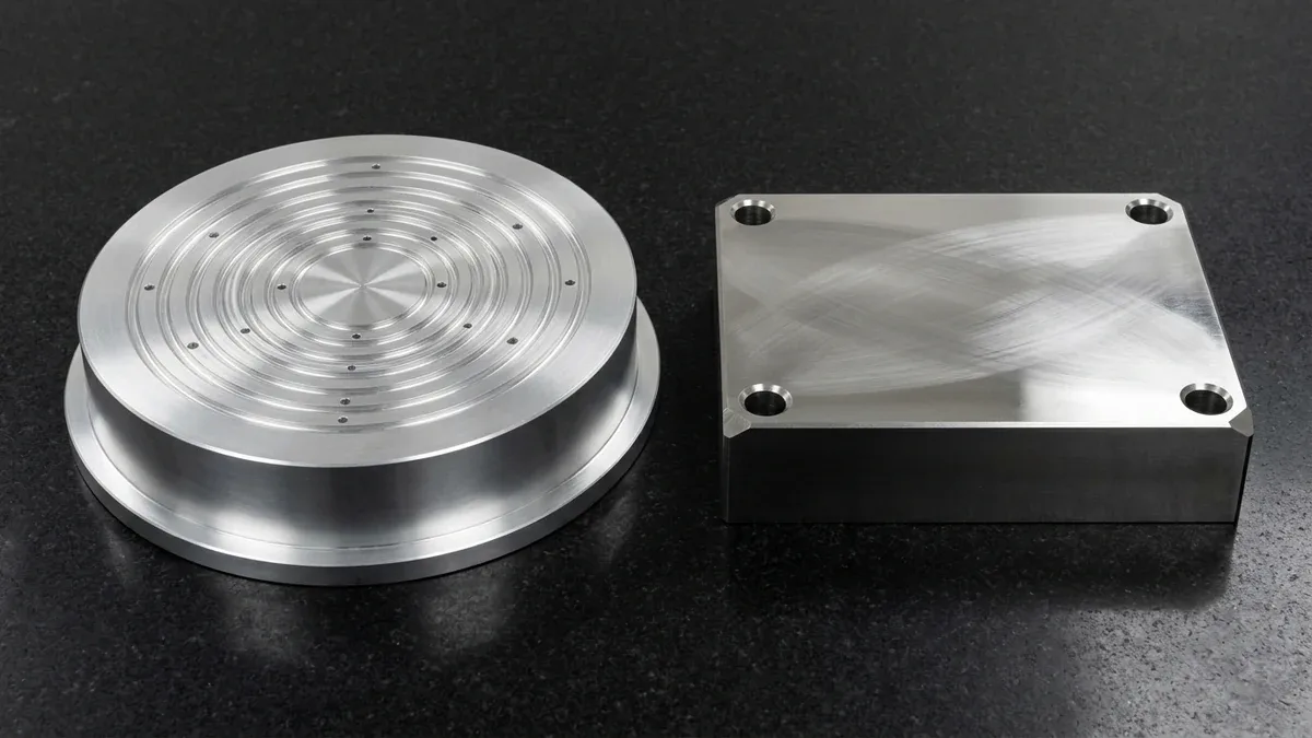
In hydraulic manifolds, semiconductor wafer vacuum chucks, and liquid-cooled Insulated-Gate Bipolar Transistor (IGBT) cold plates, mating faces require uniform planar contact. A linear thickness tolerance (15.00 ± 0.10 mm) cannot prevent macro-geometric bow, saddle warp, or twist. To govern planar form, engineers specify Geometric Dimensioning and Tolerancing (GD&T) flatness (symbol: ⏥) per ASME Y14.5 and ISO 1101.
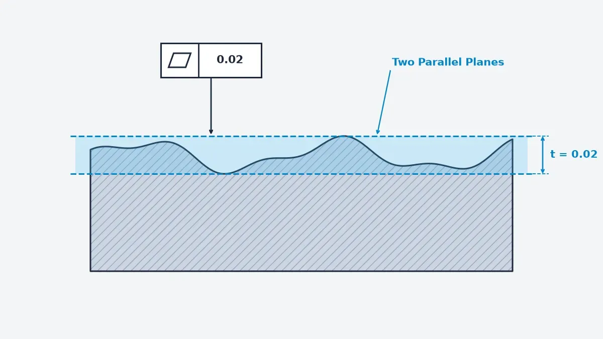
Unlike orientation or location callouts locked to external coordinate systems, the GD&T flatness symbol (⏥) is an unconstrained, self-referenced form control. Its feature control frame ([⏥ | 0.020]) defines a three-dimensional tolerance zone bounded by two parallel planes separated by distance t, without referencing any datum letter or carrying a ± sign.
At AS Prototypes, our in-house Computer Numerical Control (CNC) facility holds planar tolerances down to 0.005 mm (0.0002″) per 200 mm. Pairing stress-relieved 6061-T651 and 7075-T651 plates on our high-speed 3-axis and 4-axis CNC milling centers with Polycrystalline Diamond (PCD) fly-cutting, precision surface grinding, and Coordinate Measuring Machine (CMM) verification eliminates springback.
Executive Summary & Engineering Takeaways (BLUF)
- Two-Parallel-Plane Zone (Zero Datums & Zero MMC/LMC): GD&T flatness (
⏥) bounds all extracted surface points between two parallel planes separated by total zone widtht; datum references (A,B,C), material condition modifiers (MMC Ⓜ/LMC Ⓛ), and±signs are strictly illegal on surface flatness under ASME Y14.5-2018 and ISO 1101. - ISO 2768-2 vs. Explicit Callouts: Default
ISO 2768-mKtitle blocks pair medium linear tolerances (m) with ISO 2768-2 Class K flatness (0.20 mmover30–100 mm, vs.0.10 mmin Class H and0.40 mmin Class L); O-ring manifolds and IGBT cold plates require explicit⏥ 0.005–0.025 mmcallouts or unit-area refinements (0.05 | 0.01 / 25×25). - In-House Shop-Floor Hierarchy (per 200 mm Span): Standard 3-axis face milling holds
0.03–0.08 mm (0.0012″–0.0031″)per200 mm; stress-relieved precision PCD fly-cutting holds0.010–0.020 mm (0.0004″–0.0008″)per200 mm; precision surface grinding on a magnetic chuck holds0.005–0.010 mm (0.0002″–0.0004″)per200 mm; precision lapping achieves0.005 mm (0.0002″). - Alloy Stress-Relief & Vacuum Fixturing: Symmetric
OP10 / OP20roughing (leaving0.30–0.50 mmstock allowance), porous vacuum chucking (-85 kPa), and intermediate thermal stress-relief soaking (150–165 °Cfor1–2 hourson6061-T6 / 6061-T651vs. strictly capped≤ 100–110 °Cor room-temperature unclamped relaxation on7075-T651to prevent over-aging softening) eliminate potato-chipping distortion. - Authentic Shop-Floor Metrology: We verify flatness in our
20°C ± 1°Cmetrology room using Zeiss Bridge CMM high-density tactile scanning (ISO 12781-2ChebyshevL∞minimum-zone evaluation), Grade 00 black granite surface plates with three adjustable jack screws and0.001 mmruby lever dial indicators, Grade 00 knife-edge straightedges with feeler gauges, and3.5–6.0 barpressure-decay sealing tests.
Article Engineering Navigation
- 1. What Does the GD&T Flatness Symbol (⏥) Mean & How Does Its Tolerance Zone Work?
- 2. How Does Flatness (⏥) Differ from Parallelism (∥), Rule #1 & Surface Modifiers?
- 3. What Are the ISO 2768-2 General Flatness Classes (H, K & L) vs. Explicit Callouts?
- 4. Why Do CNC Machined Plates Bow? 4-Tier Manufacturing Hierarchy
- 5. How Do Vise Clamping Physics & Thermal Gradients Cause Unclamping Springback?
- 6. How Do We Inspect GD&T Flatness on Granite Plates, Zeiss CMMs & Leak Rigs?
- 7. Technical Engineering FAQ
1. What Does the GD&T Flatness Symbol (⏥) Mean & How Does Its Tolerance Zone Work?
GD&T flatness (symbol: ⏥) is a three-dimensional form control under ASME Y14.5-2018 (Section 5.4.2) and ISO 1101 that bounds peak-to-valley planar error (fflat = max(zi) − min(zi) ≤ tflat) between two parallel planes. While compact mounting bosses readily hold 0.015 mm (0.0006″), wide thin plates require vacuum workholding and symmetric stock removal.
In a valid feature control frame (such as [⏥ | 0.020]), the numerical value represents the total perpendicular separation t between the upper and lower bounding planes. Because those two parallel planes float freely in space to minimize peak-to-valley distance, writing a ± sign before a flatness value is a geometric syntax error.
Engineers must distinguish macro-form flatness from micro-geometric surface roughness (Ra and Rz per ISO 4287). Roughness evaluates high-frequency cutter feed marks over a short 0.8 mm (0.0315″) sampling cutoff, whereas flatness bounds long-wavelength bow, dish, crown, and twist across the entire face, as illustrated in the ASME Y14.5 schematic below.
On long structural manifolds or vacuum flanges, an overall flatness callout of 0.05 mm (0.0020″) or 0.15 mm (0.0059″) allows gradual full-span bow but fails to block steep cutter stepover ripples that cause AS568 / ISO 3601 O-ring leakage. Specifying unit-area flatness—such as [⏥ | 0.05 | 0.01 / 25×25]—caps local slope within any 25 × 25 mm patch.
When a component features multiple interrupted mounting pads separated by weight-relief pockets, applying [⏥ | 0.020] with a 4X leader controls each pad independently without forcing coplanarity. To lock interrupted pads into a single shared tolerance zone, specify the ASME Y14.5-2018 Continuous Feature (CF) symbol, the ISO 1101 Common Zone (CZ) modifier, or Profile of a Surface (⌓).
📐 Static O-Ring Gasket Squeeze & Maximum Allowable Local Flatness Calculation
For an elastomer O-ring of cross-sectional cord diameter d2 seated in a static face gland of depth hgland, surface flatness error fflat across the bolt span reduces minimum compression ratio Smin according to:
Smin (%) = [ (d2 − hgland) − fflat ] ÷ d2 × 100% | tflat,max ≤ (d2 − hgland) − (Sreq × d2)
Worked Example (AS568-2xx O-Ring: d2 = W = 3.53 mm [0.1390″], hgland = Hnom = 2.65 mm [0.1043″], Nominal Squeeze Δsnom = 0.88 mm [Snom = 24.93%]):
- Unnoted
250 mmManifold under DefaultISO 2768-mK(fflat = 0.40 mm):Smin = (0.88 − 0.40) ÷ 3.53 × 100% = 0.48 ÷ 3.53 × 100% = 13.60% < 15%→ Fails15%minimum static and20%hydraulic sealing thresholds (tflat,max ≤ 0.351 mmstatic /0.174 mmhydraulic). - Explicit Face-Milled Callout
[⏥ | 0.020](fflat = 0.020 mm):Smin = (0.88 − 0.020) ÷ 3.53 × 100% = 0.860 ÷ 3.53 × 100% = 24.36%→ Passes high-pressure sealing.
2. How Does Flatness (⏥) Differ from Parallelism (∥), Rule #1 & Surface Modifiers?
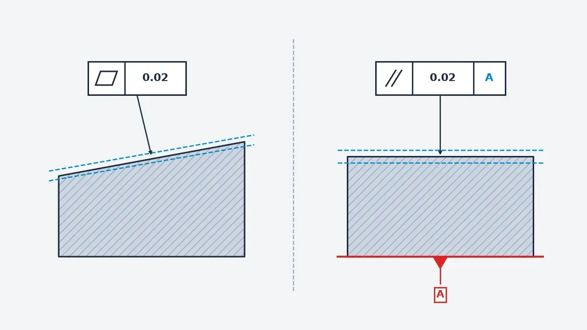
Flatness (⏥) is an unconstrained form tolerance that evaluates a surface relative only to itself with zero datum letters allowed, whereas parallelism (∥) is an orientation tolerance locking its two parallel planes parallel to a primary datum plane (Datum A). Confusing these symbols often triggers unnecessary multi-setup surface grinding costs.
Because parallelism automatically limits surface flatness within its oriented boundary, stacking both controls on one face requires the flatness tolerance to be strictly smaller than the parallelism callout (for example, [∥ | 0.050 | A] refined by [⏥ | 0.015]), as shown in the self-referenced flatness versus Datum A parallelism schematic below.
Under ASME Y14.5 Rule #1 (Envelope Principle), a feature of size such as a 12.00 ± 0.05 mm plate requires perfect form at Maximum Material Condition (MMC = 12.05 mm), automatically bounding bow to 0.10 mm. Under ISO 8015 (Independency Principle), size and form act independently unless the Envelope modifier (Ⓔ) is explicitly appended.
Because surface flatness controls a single planar face rather than a feature of size, flatness (⏥) operates strictly Regardless of Feature Size (RFS) and never permits Maximum Material Condition (Ⓜ), Least Material Condition (Ⓛ), or datum letters (A, B, C). Placing Ⓜ, Ⓛ, or any datum inside a surface flatness frame violates ASME Y14.5 and ISO 1101.
Instead, valid surface flatness modifiers include Unit-Area Flatness (such as [⏥ | 0.05 | 0.01 / 25×25]), Continuous Feature (CF) / Common Zone (CZ) for coplanar interrupted bosses, and Free-State (Ⓕ) versus Restrained Condition notes (for example, inspecting a thin cold-plate cover bolted down with 6× M6 screws torqued to 10 N·m).
| Control & Symbol | 3D Tolerance Zone | Datum / Modifiers | Typical Zone Width (mm / in) | Recommended Application / When to Choose |
|---|---|---|---|---|
| Surface Flatness (⏥) | Two unconstrained parallel planes | No Datum & No Ⓜ / Ⓛ (RFS only) | 0.005–0.050 mm (0.0002″–0.0020″) | Primary Datum A qualifying faces, O-ring seals, IGBT cold plates |
| Unit-Area Flatness (⏥ / L×L) | Local two-plane zone per unit area | No Datum & No Ⓜ / Ⓛ (Refinement) | 0.05 | 0.01 / 25×25 mm | Long vacuum flanges and hydraulic manifolds preventing local ripples |
| Free-State / Coplanar (⏥ Ⓕ / CF / CZ) | Two parallel planes (unclamped or shared) | No Datum & No Ⓜ / Ⓛ (Ⓕ, CF, CZ) | 0.015–0.100 mm (0.0006″–0.0039″) | Flexible thin covers (Ⓕ or restrained note) and interrupted pads |
| Parallelism (∥) | Two parallel planes locked to Datum A | Mandatory Datum Reference (A) | 0.005–0.050 mm (0.0002″–0.0020″) | Opposed bearing housings, mold bolster plates, precision spacers |
| Profile of a Surface (⌓) | 3D boundary disposed about true CAD | Optional Datum (nX / Coplanar) | 0.020–0.100 mm (0.0008″–0.0039″) | Coplanar interrupted mounting bosses and stepped housing faces |
3. What Are the ISO 2768-2 General Flatness Classes (H, K & L) vs. Explicit Callouts?
When an engineering drawing title block specifies ISO 2768-mK without an explicit ⏥ feature control frame, the lowercase m invokes ISO 2768-1 medium linear size tolerances, while the uppercase K invokes ISO 2768-2 Class K general geometrical tolerances for flatness, straightness, and perpendicularity. Engineers must never write non-existent hybrids like ISO 2768-fH to represent ±0.010 mm.
Under ISO 2768-2 Table 1, the general flatness tolerance is determined by the longer lateral dimension of the planar surface across six nominal length bands. Tighter general drawings invoke Class H, standard CNC shop drawings default to Class K (ISO 2768-mK), and heavy structural fabrications use Class L, as detailed below.
| Nominal Longest Span (mm) | Class H (Fine Geometrical) | Class K (Medium — ISO 2768-mK Default) | Class L (Coarse Geometrical) | Recommended Application / When to Choose |
|---|---|---|---|---|
| Up to 10 mm | 0.02 mm (0.0008″) | 0.05 mm (0.0020″) | 0.10 mm (0.0039″) | Small sensor standoff pads, miniature bosses, optomechanical tabs |
| Over 10 to 30 mm | 0.05 mm (0.0020″) | 0.10 mm (0.0039″) | 0.20 mm (0.0079″) | Compact connector flanges, localized bolting lands, relay blocks |
| Over 30 to 100 mm | 0.10 mm (0.0039″) | 0.20 mm (0.0079″) | 0.40 mm (0.0157″) | Standard NEMA motor mounts, non-sealing brackets, bearing caps |
| Over 100 to 300 mm | 0.20 mm (0.0079″) | 0.40 mm (0.0157″) | 0.80 mm (0.0315″) | General enclosure lids, structural side plates (add explicit ⏥ for seals) |
| Over 300 to 1,000 mm | 0.30 mm (0.0118″) | 0.60 mm (0.0236″) | 1.20 mm (0.0472″) | Large automation baseplates, gantry beams, battery pack trays |
| Over 1,000 to 3,000 mm | 0.40 mm (0.0157″) | 0.80 mm (0.0315″) | 1.60 mm (0.0630″) | Long machine frames, conveyor weldments, chassis rails |
For a 250 mm × 180 mm electronics enclosure lid, the longest span (250 mm) falls into the 100–300 mm band, where default ISO 2768-mK permits 0.40 mm (0.0157″) of bow. While economical for non-sealing covers, thermal cold plates and hydraulic manifolds require explicit [⏥ | 0.010] to [⏥ | 0.025] blueprint callouts.
4. Why Do CNC Machined Plates Bow? 4-Tier Manufacturing Hierarchy
Machined metal plates bow when asymmetric roughing removes a stressed surface layer of thickness Δt carrying residual rolling or cold-water quenching stress σres, inducing residual-stress curvature (δstress = [3 × σres × Δt × L2] ÷ [4 × E × t2]). Raw extruded bar starts at 0.20–0.80 mm / 100 mm, whereas we execute a four-stage shop-floor workflow:
- Select Pre-Stretched Tooling Stock & Execute Symmetric Roughing (0.03 to 0.08 mm per 200 mm [0.0012″–0.0031″] on Standard 3-Axis Face Milling): For milled aluminum plates, we specify
6061-T651or7075-T651pre-stretched plate (mechanically stretched1.5%–3.0%after solution quenching to neutralize internal compressive skin stresses) and machine equal stock from both faces via alternatingOP10 / OP20flip-milling passes, leaving a uniform0.30–0.50 mmsemi-finishing allowance. - Apply Alloy-Specific Intermediate Thermal Stress-Relief Annealing: Between roughing (
0.30–0.50 mmstock allowance) and finish fly-cutting or skim-milling,6061-T6and6061-T651plates undergo intermediate stress-relief soaking at150–165 °C (302–329 °F)for1–2 hours. Conversely, because7075-T651has an artificial aging ceiling near120 °C, thermal relaxation on7075-T651is strictly capped at≤ 100–110 °C (212–230 °F)(or24-hourroom-temperature unclamped stress relaxation) to prevent over-aging softening. - Finish-Mill via Single-Point PCD Fly-Cutting on Porous Vacuum Chucks (0.010 to 0.020 mm per 200 mm [0.0004″–0.0008″], Ra 0.4–0.8 µm): On our 3-axis vertical machining centers, non-magnetic aluminum (
6061-T651,7075-T651) and austenitic stainless steel (304,316L) plates are held on a porous ceramic or grooved aluminum vacuum chuck at-85 kPa. A balanced single-point PCD fly-cutter or carbide skim mill runs atVc = 450–800 m/min,fz = 0.04–0.08 mm/tooth, and axial depthap = 0.05–0.10 mmunder20 °Cchilled flood coolant. - Finish-Grind Ferromagnetic Steels on a Magnetic Chuck (0.005 to 0.010 mm per 200 mm [0.0002″–0.0004″]) or Precision-Lap (0.005 mm [0.0002″]): For ferromagnetic quenched-and-tempered
4140steel (28–45 HRC), hardened cold-work tool steels (D2,SKD11, and440Cat58–62 HRCper ASTM E18), and martensitic17-4PHstainless plates, high spots are shimmed in the free state on a fine-pole electromagnetic chuck before taking0.005 mmreciprocating surface-grinding spark-out passes, followed by planetary cast-iron diamond lapping (0.005 mm,Ra 0.05–0.1 µm) for high-pressure sealing plates.
When to Avoid Over-Tolerancing: Never specify ⏥ 0.005 mm across flexible thin-walled aluminum housings (t < 3.0 mm) or unannealed structural weldments. Instead, design raised coplanar mounting islands around bolt holes and control them with local flatness or Profile of a Surface (⌓) to reduce machining cycle time and fixture cost.
Post-Machining Coating Growth Rules: Engineers must also account for surface treatment film physics on precision datum faces. Under ASTM A967, stainless steel passivation adds 0.000 mm (~2 nm passive film), whereas MIL-A-8625 Type II/III anodizing grows 50% inward and 50% outward (+0.5t per wall), and ASTM B733 electroless nickel plating builds 100% outward (+1.0t per wall).
| Material / Process Tier | Achievable Flatness (per 200 mm) | Roughness (Ra) | Relative Cost & Ex-Factory Lead Time | Recommended Application / When to Choose |
|---|---|---|---|---|
| Cast Tooling Plate (MIC-6 / Alca-5 / 5083-H111 Raw) | 0.15–0.38 mm (0.0059″–0.0150″) | 0.8–1.6 µm (32–63 µin) | 1.0x | 4–8 Business Days | Unmachined automation baseplates and fixture subplates |
| Tier 1: Standard 3-Axis CNC Face Milling | 0.03–0.08 mm (0.0012″–0.0031″) | 0.8–1.6 µm (32–63 µin) | 1.2x | 4–8 Business Days | General structural brackets, motor mounts, and housing covers |
| Tier 2: Stress-Relieved Precision PCD Fly-Cutting | 0.010–0.020 mm (0.0004″–0.0008″) | 0.4–0.8 µm (16–32 µin) | 1.5x | 4–8 Business Days | 6061-T6 / 6061-T651 / 7075-T651 IGBT cold plates and manifolds |
| Tier 3: Precision Surface Grinding on Magnetic Chuck | 0.005–0.010 mm (0.0002″–0.0004″) | 0.2–0.4 µm (8–16 µin) | 2.1x | 7–12 Business Days | Hardened 4140 / D2 / 440C die plates and datum blocks |
| Tier 4: Planetary Cast-Iron & Diamond Lapping | 0.005 mm (0.0002″) | 0.05–0.1 µm (2–4 µin) | 3.2x | 7–12 Business Days | High-pressure 0.005 mm hydraulic sealing plates and valve discs |
5. How Do Vise Clamping Physics & Thermal Gradients Cause Unclamping Springback?
In our in-house CNC shop-floor production logs, the primary cause of flatness rejection on plates under 12 mm (0.472″) thick is elastic vise-jaw buckling (“potato-chipping”) combined with vertical thermal gradient bow. When lateral vise jaws grip the top edge of a thin plate above its neutral axis, the eccentric bending moment arches the center upward during cutting.
Once the cutter machines that arched top surface flat and the operator releases the vise, elastic recovery pulls the center downward into a concave dish. We eliminate this defect via a closed-loop Symptom → Root Cause → Corrective Action engineering workflow:
- Symptom: A
200 × 150 × 8.0 mm6061-T651liquid-cooled cold plate measures flat within0.008 mmwhile clamped inside a Kurt vise, but springs into a0.038 mm (0.0015″)concave dish upon release, failing[⏥ | 0.015]. - Root Cause: Excess lateral vise clamping pressure elastically bows the plate center upward by
δclamp = 0.022 mm (0.00087″)during face milling, while aΔT = 1.1 °Ctop-to-bottom cutting temperature gradient induces an additionalδbow = 0.0159 mm (≈ 0.016 mm)thermal camber that inverts after cooling and unclamping. - Corrective Action: Switch to a porous vacuum chuck at
-85 kPa(or low-profile toe clamps with torque-limited15 N·mfasteners) paired with20 °Cchilled flood coolant and a0.08 mmPCD fly-cutter skim pass, holding free-state flatness at0.0090 mm (0.00035″).
📐 Shop-Floor Thermal Bowing & Clamping Elastic Springback Calculation
For a plate of span L, width b, thickness t, and modulus E under jaw force Fjaw at eccentricity e (clamping springback δclamp = [3 × Fjaw × e × L2] ÷ [2 × E × b × t3]) and thermal camber δbow = (α × ΔT × L2) ÷ (8 × t), total flatness error Δztotal is:
δbow = (α × ΔT × L2) ÷ (8 × t) | Δztotal = δclamp + δbow
Worked Example (L = 200 mm [L2 = 40,000 mm2], t = 8.0 mm [8 × t = 64.0 mm], α = 23.1 × 10⁻⁶ / °C for 6061-T6 / 6061-T651):
- Kurt Vise + Standard Coolant (
δclamp = 0.022 mm,ΔT = 1.1 °C):δbow = (23.1 × 10-6 × 1.1 × 40,000) ÷ 64.0 = 1.0164 ÷ 64.0 = 0.01588 mm (≈ 0.0159 mm)→Δztotal = 0.022 + 0.0159 = 0.0379 mm (≈ 0.038 mm / 0.0015″)→ Fails[⏥ | 0.015]. - Porous Vacuum Chuck + 20 °C Chilled Coolant (
δclamp = 0.005 mm,ΔT = 0.28 °C):δbow = (23.1 × 10-6 × 0.28 × 40,000) ÷ 64.0 = 0.25872 ÷ 64.0 = 0.00404 mm (≈ 0.0040 mm)→Δztotal = 0.005 + 0.0040 = 0.0090 mm (0.00035″)→ Passes. - Asymmetric Residual-Stress Skin Removal (
L = 200 mm,h = 6.0 mm,E = 68,900 MPa,Δσ = 35 MPaacross10%milled skinΔt = 0.60 mm[Δt ÷ h = 0.10]):Δδ = (3 × 35 × 0.60 × 40,000) ÷ (4 × 68,900 × 36.0) = 420,000 ÷ 1,653,600 = 0.254 mm (0.0100″)→ Severe unannealed bow without symmetricOP10/OP20roughing. - Thermal Camber on
250 × 10 mmPlate (L = 250 mm[L2 = 62,500 mm2],h = 10 mm[8 × h = 80 mm],α = 23.1 × 10⁻⁶ K-1): Under aΔT = 1.2 Kcoolant gradient,Δz = (23.1 × 10-6 × 1.2 × 62,500) ÷ 80 = 1.7325 ÷ 80 = 0.0217 mm (0.00085″)(whereas an unchilledΔT = 12 Kdry-milling gradient bows to17.325 ÷ 80 = 0.217 mm; a300 × 15 mmplate atΔT = 4 Kbows0.0693 mm).
6. How Do We Inspect GD&T Flatness on Granite Plates, Zeiss CMMs & Leak Rigs?
Verifying a datum-free GD&T flatness callout requires unconstrained workpiece support inside our 20°C ± 1°C climate-controlled metrology room. For rapid at-the-machine screening on milled plates (⏥ 0.030–0.100 mm), machinists place a Grade 00 hardened steel knife-edge straightedge across the diagonal axes and check light-gap clearance with calibrated feeler gauges (0.005–1.00 mm blades).
For precision fly-cut and surface-ground plates (⏥ 0.005–0.025 mm), inspectors support the part on a Grade 00 black granite surface plate using three adjustable screw jacks. After leveling three corners to zero, the inspector sweeps a 0.001 mm (1.0 µm) ruby lever dial test indicator (DTI) on a precision height gauge to record Full Indicator Movement (FIM).
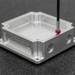
For First Article Inspection (FAI), our Zeiss Bridge CMMs (available upon request) perform high-density tactile scanning across a 25-point to 64-point (X, Y, Z) grid—never just four corners, which misses center dish warpage. Because Least-Squares (L2) fitting overestimates flatness by 12%–18%, we evaluate true ISO 12781-2 Minimum-Zone (Chebyshev L∞, fflat = max(zi) − min(zi)) flatness as shown below.
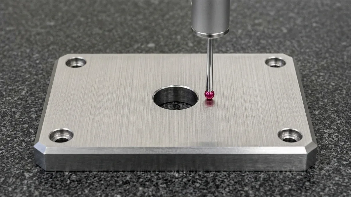
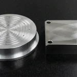
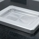
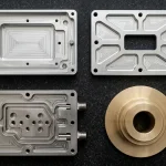
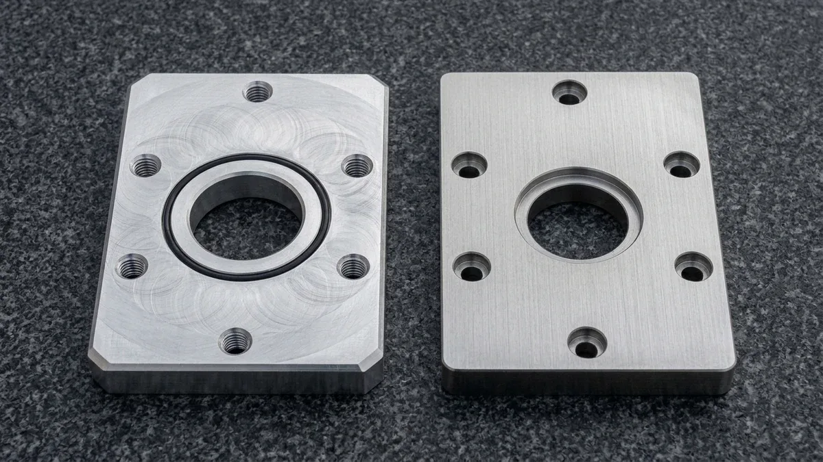
As shown below, machining kinematics directly govern achievable flatness and sealing integrity. Multi-pass face milling on a 6061-T6 manifold subplate leaves cycloidal cutter marks around its central fluid bore and seated O-ring groove (⏥ 0.020 mm), whereas surface grinding and lapping on a mating 4140 steel cover plate achieve mirror planarity (⏥ 0.005 mm, Ra 0.1 µm).
Our in-house inspection team verifies these ground and lapped sealing faces (0.005 mm [0.0002″]) directly using Zeiss Bridge CMM Chebyshev grid probing (ISO 12781-2), Grade 00 granite plate 0.001 mm ruby lever DTI sweeping on three jack screws, ISO 4287 contact stylus profilometry (Ra / Rz), and 3.5–6.0 bar air/hydrostatic water pressure-decay sealing tests.
| In-House Inspection Method | Resolution / Test Parameter | Target Flatness Window | Workpiece Support & Fitting Rule | Recommended Application / When to Choose |
|---|---|---|---|---|
| Grade 00 Knife-Edge Straightedge & Feeler Gauges | 0.005–1.00 mm calibrated steel blades | 0.030–0.400 mm (0.0012″–0.0157″) | Unclamped free state across 6 diagonal/axial chords | In-process CNC machine check for ISO 2768-mK covers and frames |
| Grade 00 Granite Plate + 3 Jack Screws + 0.001 mm Lever DTI | 0.001 mm (1.0 µm / 0.00004″) ruby lever indicator | 0.005–0.030 mm (0.0002″–0.0012″) | Leveled on 3 adjustable jack screws; Full Indicator Movement (FIM) | Shop-floor verification of PCD fly-cut plates and surface-ground blocks |
| 20°C ± 1°C Zeiss Bridge CMM High-Density Scanning | 25–64+ tactile points (ISO 12781-2 Chebyshev L∞) | 0.005–0.050 mm (0.0002″–0.0020″) | Minimum-Zone fflat = Zmax − Zmin across 5 grid coordinates (+0.004, −0.008, +0.011, −0.005, +0.002 mm): +0.011 − (−0.008) = 0.019 mm ≤ 0.020 mm | Formal FAI dimensional reports for datum plates, manifolds, and chucks |
| Air & Hydrostatic Water Pressure-Decay Leak Testing | 3.5–6.0 bar (50.8–87.0 PSI) hold test + ISO 4287 stylus Ra | 0.005–0.020 mm (0.0002″–0.0008″) | Bolted mating seal plate with calibrated pressure transducer | Functional sealing sign-off on IGBT cold plates and O-ring manifolds |
Ex-Factory Turnaround & Transit: We deliver DFM reviews within 24 hours, as-machined prototypes in 4 to 8 business days, anodized (MIL-A-8625), passivated (ASTM A967), or surface-ground parts in 7 to 12 business days, and production batches in 7 to 30 business days. All schedules reflect Ex-Factory Turnaround, strictly separated from 3 to 5 business days DHL/FedEx/UPS air transit.
🔗 Related Precision Machining & GD&T Engineering Guides
- High-Speed 3-Axis & 4-Axis CNC Milling Services — Pre-stretched
6061-T651and7075-T651manifold and cold-plate machining on porous vacuum chucks. - CMM Precision Metrology & GD&T Verification Guide — How Zeiss bridge CMMs evaluate Minimum Zone (Chebyshev) form and orientation callouts.
- Preventing Deformation and Residual Stress in CNC Milling Aluminum — Symmetric
OP10/OP20roughing and stress-relieved plate selection to eliminate warping.
7. Technical Engineering FAQ
GD&T flatness (⏥) is an unconstrained form control that evaluates a single surface relative only to itself within two parallel planes separated by tolerance t. Referencing a datum plane governs angular orientation instead, which requires the parallelism symbol (∥) under ASME Y14.5 and ISO 1101.
Yes, engineers stack both callouts when a face requires broad angular alignment to a datum alongside tighter sealing planarity. Because parallelism automatically bounds surface form, the flatness refinement must be strictly smaller than the parallelism zone (such as ∥ 0.050 mm refined by ⏥ 0.015 mm).
In ISO 2768-mK, the capital letter K invokes ISO 2768-2 general geometrical tolerances for flatness based on the longest surface span. Class K permits 0.05 mm up to 10 mm, 0.10 mm for 10–30 mm, 0.20 mm for 30–100 mm, and 0.40 mm for 100–300 mm.
Specify pre-stretched 6061-T651 tooling plate rather than extruded 6061-T6 bar, and execute symmetric OP10/OP20 roughing cuts removing equal stock from both faces. Finish the critical planar face on a porous vacuum chuck using a single-pass PCD fly-cutter under 20°C flood coolant to eliminate vise buckling springback.
Need Verified GD&T Flatness on Your Custom Machined & Ground Plates?
Upload your 3D CAD models (STEP/IGES) and 2D tolerance drawings for a comprehensive manufacturability review, vacuum-chuck fixturing strategy, and custom production quotation backed by full Zeiss CMM Minimum Zone inspection reports.
Request a GD&T Engineering Quote & DFM Review →