

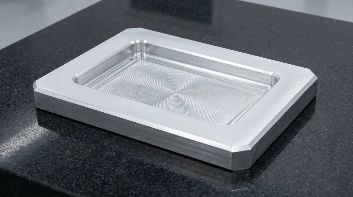
When designing machined enclosures, mating cavities, and functional pockets, 2D engineering drawings frequently specify razor-sharp 90-degree internal corners. In computer-aided design (CAD) software, modeling a theoretical zero-radius intersection requires only a single click. However, in physical manufacturing, producing true sharp corners in CNC machining is mechanically impossible using standard rotary cutting tools.
Because all standard end mills rotate about a central spindle axis, their cutting flutes naturally generate a cylindrical path. Consequently, every rotary milling pass leaves behind a concave internal fillet radius exactly equal to half the cutter diameter (R = D/2). Attempting to force an end mill into a sharp corner without proper design for manufacturing (DFM) provisions leads to catastrophic tool deflection, intense harmonic chatter, premature tool breakage, and surging machining cycle times.
At AS Prototypes, our in-house precision machine shop operates high-speed 3-axis and 4-axis vertical machining centers (VMCs) alongside ultra-fine wire and sinker electrical discharge machining (EDM) cells. In this comprehensive technical guide, our manufacturing engineers analyze the mechanical kinematics of corner radii, detail proven corner relief geometries such as dogbones and T-bones, evaluate deep-pocket filleting ratios, and review non-rotary precision processes capable of achieving true zero-radius corners.
BLUF: Key Engineering Rules for Inside CNC Corners
- Rotary Tool Radius Rule: Rotary end mills cannot physically generate sharp inside corners; they always leave an internal fillet radius equal to the cutter radius (R = D/2).
- Radial Engagement Spike: Driving a cutter into a 90-degree corner spikes radial tool engagement from a nominal 45 degrees to 180 degrees, multiplying instantaneous cutting forces and triggering heavy chatter.
- The 10% to 15% Oversize Standard: Always design internal corner radii at least 10% to 15% larger than the finishing tool radius (R_pocket ≥ 1.15 × r_tool) to enable continuous circular arc interpolation.
- Clearance Undercuts for Mating Parts: When square blocks must seat flush inside milled pockets, deploy dogbone, T-bone, or circular undercuts rather than requiring sharp corner milling.
- Non-Rotary Processes for True 90-Degree Corners: When undercuts are prohibited, deploy precision Wire EDM (R ≤ 0.05 mm), Sinker EDM (R ≤ 0.02 mm), or rotary broaching.
The Kinematics and Physics of Rotary Cutters in Internal Corners
To understand why sharp inside corners cannot be milled, one must examine the fundamental kinematics of cylindrical cutting tools. Whether utilizing a 2-flute carbide slotting mill or a 4-flute finishing end mill, the tool removes metal as its peripheral cutting edges rotate across the workpiece material at thousands of revolutions per minute.
When an end mill traverses a straight linear pocket wall, it maintains a predictable, constant radial depth of cut (a_e). For example, during a typical semi-finishing pass on 6061-T6 aluminum, radial engagement may represent 15% to 25% of tool diameter, corresponding to a radial contact arc between 45 degrees and 60 degrees. Along this straight trajectory, cutting forces remain balanced, chip evacuation is continuous, and tool deflection is negligible.
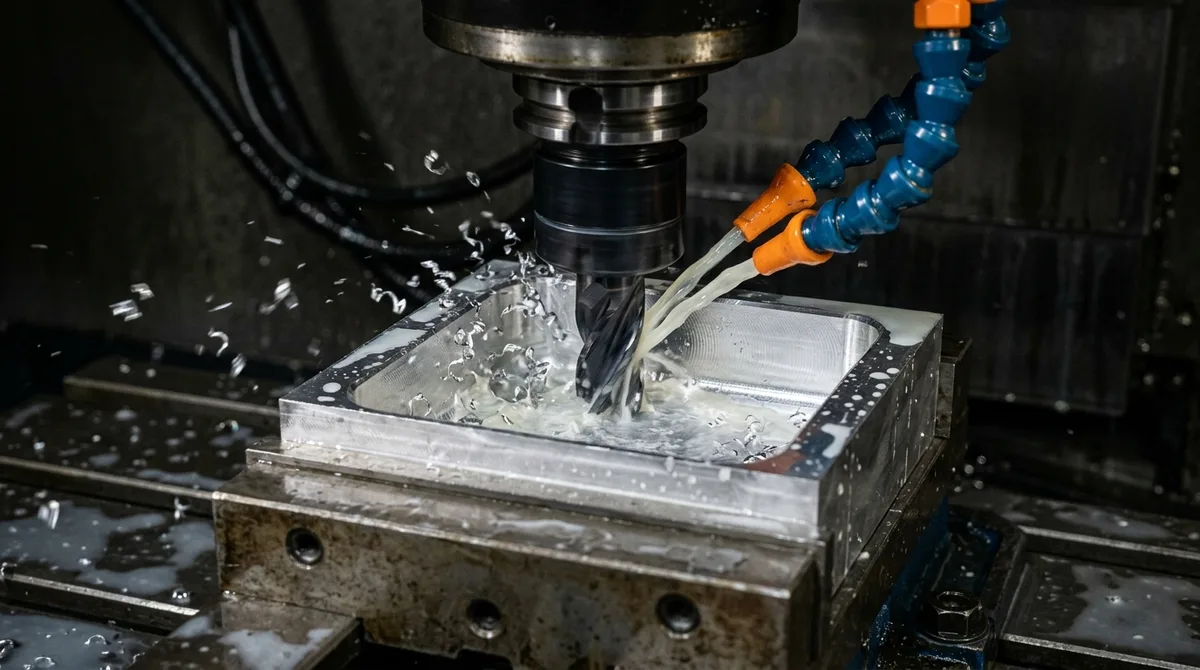
However, the moment the end mill approaches the intersection of two perpendicular walls to form a 90-degree corner, the tool engagement kinematics change violently. If the corner radius in CAD matches the cutter radius exactly (R = r_tool), the tool must drive directly into the vertex and stop before changing direction by 90 degrees. At that exact corner vertex, the cutter engagement arc instantaneously surges from its nominal 45 degrees up to a massive 180 degrees of full semi-circular wrap-around.
This drastic surge in tool-workpiece contact area generates severe mechanical consequences:
- Instantaneous Force Spike: Cutting pressure spikes exponentially as all flutes engage material simultaneously, transferring immense bending moments to the tool shank.
- Cantilever Deflection: According to classical beam mechanics, tool deflection (y) follows the relation y = (F × L³) / (3 × E × I), where tool stiffness scales with the fourth power of diameter (D&sup4;) and deflection scales with the cube of tool overhang (L³). When cutting forces surge in the corner, the tool flexes away from the programmed path.
- Regenerative Chatter: The rapid deflection and sudden release of cutting pressure excite machine harmonics, producing high-frequency chatter marks on the pocket walls and damaging surface finish (increasing Ra beyond 3.2 μm).
- Chipping and Tool Breakage: Micro-fractures quickly propagate across the brittle tungsten carbide flutes, resulting in chipped cutting corners or sudden catastrophic tool breakage deep inside expensive parts.
The 10% to 15% Oversize Corner Fillet Rule
To eliminate the destructive 180-degree engagement spike, manufacturing engineers apply a foundational CNC rule: always specify an inside corner radius slightly larger than the radius of the cutting tool intended to finish it. As a general engineering guideline, the corner radius should be oversized by 10% to 15%:
When R_pocket is larger than r_cutter, computer-aided manufacturing (CAM) software generates a continuous circular toolpath trajectory (G02 or G03 circular interpolation) around the corner. The cutter smoothly rolls into the corner, maintains a controlled radial engagement angle below 90 degrees, and preserves forward feed velocity without coming to a complete dead halt. This smooth deceleration and rolling motion prevents tool chatter, enhances surface finish down to Ra 0.8 μm, and substantially extends cutting tool life.
Inside Corner Relief Engineering: Dogbone vs T-Bone vs Radial Undercuts
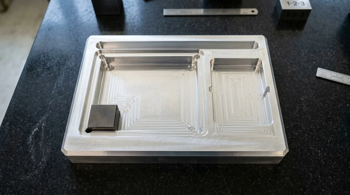
In mechanical assemblies, designers frequently need to mount perfectly rectangular components—such as lithium-ion battery cells, optical prisms, electronic printed circuit boards (PCBs), or hardened tool steel die inserts—inside a milled aluminum or steel pocket. If the pocket has rounded internal corners, the square corners of the mating component will collide with the pocket fillets, preventing the block from seating flush against the reference datums.
Instead of resorting to costly secondary operations to square the corners, design engineers incorporate specialized corner undercuts (reliefs). These geometries remove the interfering material at the vertex, allowing square corners to pass unobstructed while permitting standard rotary milling.
1. Dogbone Corner Reliefs (Diagonal Overcuts)
A dogbone relief is created by programming the milling cutter to extend diagonally along the 45-degree corner bisector, cutting slightly past the corner vertex before retracting. This produces a circular lobe centered along the diagonal that clears the interfering material.
To ensure a square block with corner coordinates (0, 0) completely clears the circular relief cut by an end mill of radius (r), the center of the tool must travel along the 45-degree diagonal to a distance calculated by:
Dogbone reliefs provide symmetric stress distribution around the corner vertex, making them the preferred choice for structural aerospace enclosures, sealed fluid manifolds, and load-bearing brackets.
2. T-Bone Corner Reliefs (Single-Edge Overcuts)
While dogbone reliefs extend diagonally, a T-bone relief shifts the overcut along only one straight wall of the pocket. The cutter continues straight past the corner along the primary wall by a distance equal to the cutter radius, clearing the corner without cutting into the perpendicular wall.
T-bone undercuts offer a decisive aesthetic and functional benefit: one of the two mating walls remains completely straight and unbroken. When an assembly utilizes a top cover plate or flange with a matching lip, the T-bone overcuts can be oriented along the hidden edge, concealing the reliefs entirely from external view while maintaining full flush mating.
3. Corner Relief Holes (Drilled Pre-Reliefs)
For high-volume production or heavy steel plates, machining corner undercuts with small end mills can consume valuable cycle time. A highly efficient alternative is drilling corner relief holes prior to pocket roughing. A standard twist drill punches through-holes or blind holes at the four corner coordinates. Subsequently, a large, rigid roughing end mill clears the central pocket volume at high metal removal rates without ever encountering corner engagement spikes.
The Male Mating Part DFM Alternative
Experienced DFM engineers recognize that modifying the female pocket is not always the best path. Often, the simplest, most cost-effective solution is modifying the male component. By chamfering or rounding the external corners of the mating block (for example, applying a 45-degree chamfer C ≥ 1.5 × R_pocket), the male part clears the natural CNC fillet radius effortlessly. This eliminates all pocket undercuts, reduces machine programming time, and preserves 100% of the pocket wall rigidity.
Pocket Depth-to-Diameter Ratios and Stepped Corner Filleting
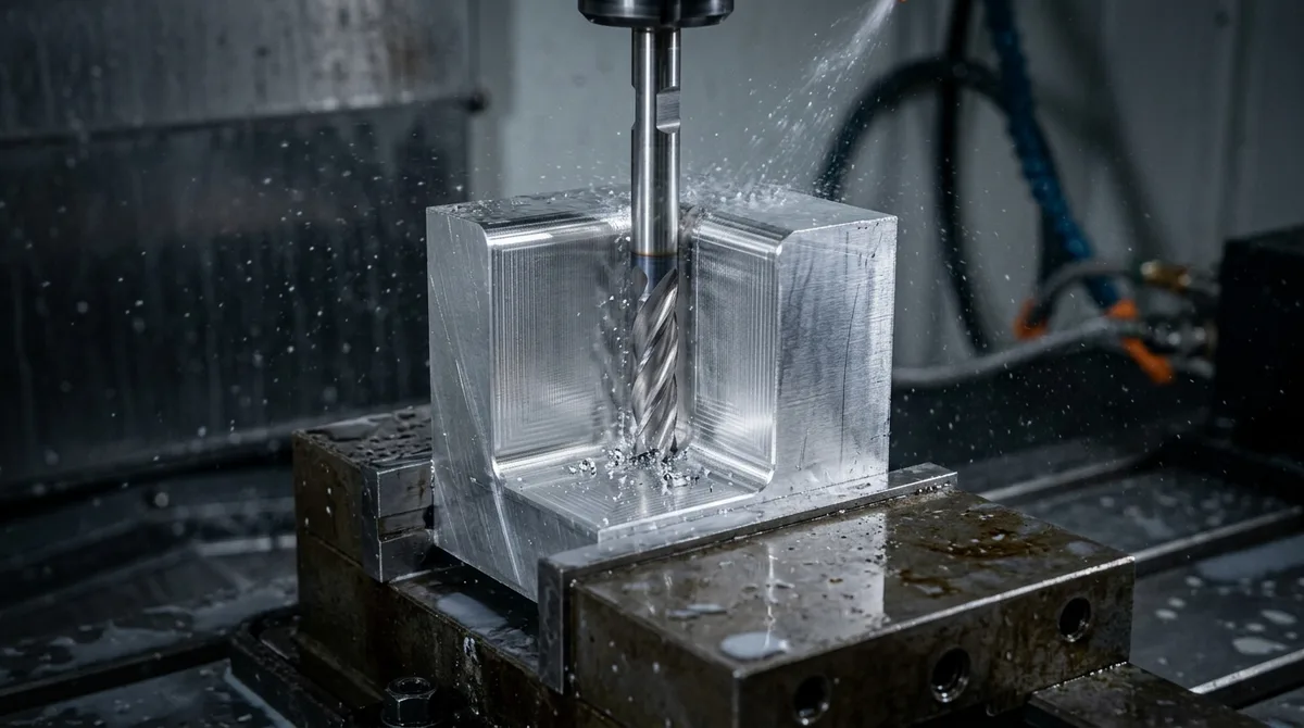
The manufacturability and cost of internal corner fillets are inextricably linked to pocket depth. In CNC milling, the aspect ratio between tool overhang length (L) and cutter diameter (D)—the L/D ratio—dictates machining rigidity.
As cutter diameter decreases to fit a small corner radius, its resistance to bending deflection drops drastically. Recalling that deflection is inversely proportional to the fourth power of diameter (D&sup4;), halving the tool diameter increases deflection by 16 times under identical cutting forces. When combined with long tool reach in deep pockets, tool chatter becomes severe.
Aspect Ratio Zones in Pocket Corner Machining
- Standard Rigidity Zone (L/D ≤ 3:1): Standard solid carbide end mills operate with maximum dynamic stiffness. High feed rates and aggressive axial step-downs can be maintained while holding tight dimensional tolerances (±0.015 mm).
- Moderate Reach Zone (L/D = 3:1 to 5:1): Tool deflection begins to influence wall straightness and corner taper. Machinists must reduce feed per tooth by 30% to 50% and implement multiple light spring passes to achieve acceptable corner perpendicularity.
- High-Deflection Deep Pocket Zone (L/D > 5:1 to 8:1): Standard cutters cannot operate without severe harmonic vibration. Machinists must deploy necked-shank carbide tools, shrink-fit holders, or tuned vibration-damped tool shanks, drastically increasing cycle times and machining costs.
The Stepped Corner Radius Strategy
When an internal feature requires significant cavity depth but functional requirements call for a small corner radius at the floor, demanding a uniform small radius across the full depth is a costly design error. For instance, requiring a continuous R 1.5 mm fillet down a 40 mm deep pocket forces the machinist to finish the entire wall using a Ø 3.0 mm end mill with an extreme L/D ratio of over 13:1—a setup guaranteed to chatter or snap.
The optimal DFM solution is implementing a stepped corner radius. The upper 70% to 80% of the pocket depth incorporates a generous radius (such as R 5.0 mm to R 6.0 mm), which can be roughed and finished rapidly using a rigid, vibration-free Ø 10 mm or Ø 12 mm cutter. Only the bottom 20% of the corner where the mating component interfaces transitions down to the required R 1.5 mm fillet using a short-reach finishing tool. This hybrid geometry reduces finishing cycle times by up to 65% while delivering superior wall perpendicularity.
| Pocket Depth Range | Recommended Finishing Tool (D) | Optimal Fillet Radius (R) | Maximum Practical L/D | Shop Floor Machining Strategy |
|---|---|---|---|---|
| 0 mm to 12 mm | Ø 4.0 mm to Ø 6.0 mm | R 2.5 mm to R 3.5 mm | 2.5:1 (High Rigidity) | Standard 3-axis VMC roughing and finishing with solid carbide end mills. |
| 12 mm to 30 mm | Ø 6.0 mm to Ø 8.0 mm | R 3.5 mm to R 5.0 mm | 4.0:1 (Moderate) | High-speed dynamic trochoidal roughing; dual spring finishing passes for wall taper. |
| 30 mm to 60 mm | Ø 10.0 mm to Ø 12.0 mm | R 6.0 mm to R 8.0 mm | 5.5:1 (Deflection Risk) | Deploy neck-relieved solid carbide cutters; implement stepped corner radii if floor requires small fillet. |
| Above 60 mm | Ø 16.0 mm to Ø 20.0 mm | R 10.0 mm or larger | > 6:1 (Deep Reach) | Modular anti-vibration carbide shanks; evaluate Wire EDM or multi-part bolted construction. |
Alternative Non-Rotary Processes for True 90-Degree Inside Corners
When technical drawings, optical paths, or strict sealing specifications prohibit any corner relief undercuts and mandate a true razor-sharp 90-degree internal corner, rotary milling reaches its physical boundary. In such scenarios, AS Prototypes deploys non-rotary precision subtractive processes.
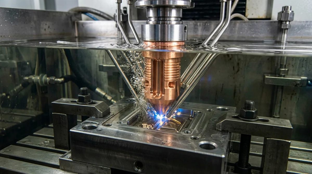
1. Wire Electrical Discharge Machining (WEDM)
Wire EDM is the premier industrial solution for producing near-zero radius internal corners in electrically conductive materials, including hardened tool steels (D2, A2, H13, 60 HRC), high-strength titanium alloys, and stainless steels. WEDM operates by running a continuous spool of micro-diameter brass or coated wire between upper and lower diamond guides, eroding conductive metal through localized high-frequency electrical spark discharges inside a deionized water dielectric bath.
Because the cutting wire travels linearly through the workpiece, the internal corner radius is governed purely by wire radius plus spark gap:
Deploying standard Ø 0.25 mm brass wire yields an internal corner radius of approximately R 0.14 mm to R 0.16 mm. When ultra-sharp corners are mandatory, our facility utilizes fine micro-wire setups (Ø 0.10 mm or Ø 0.05 mm wire) to achieve microscopic corner radii down to R 0.03 mm to R 0.05 mm with dimensional accuracy of ±0.005 mm. The primary limitation is geometric: Wire EDM requires a through-hole or open pass-through for the continuous wire strand, making it unsuitable for blind cavities.
2. Sinker EDM (Plunge Cavity Erosion)
For blind pockets, square mold cavities, and internal blind keyways where wire cannot pass through, Sinker EDM (Ram EDM) provides the definitive solution. A custom-shaped male electrode—machined to tight tolerances from fine-grain POCO graphite or copper-tungsten—is plunged axially into the workpiece inside a dielectric hydrocarbon oil tank.
The electrical sparks erode the workpiece into the exact negative profile of the electrode. By CNC milling the electrode corner with microscopic cutting tools and applying controlled orbital spark discharge cycles, Sinker EDM produces blind internal square corners with radii as small as R 0.02 mm to R 0.05 mm, complete with pristine surface finishes down to VDI 12 (Ra 0.4 μm).
3. Rotary Broaching and CNC Slotting
When working with softer ductile alloys such as 6061-T6 aluminum, C3604 brass, or mild carbon steels, internal square holes and rectangular keyways can be produced directly on CNC machining centers using rotary broaching or motorized slotting heads.
A rotary broach holds an internal polygon cutter tilted at a slight 1-degree wobble angle. As the tool rotates synchronously with the spindle, a shearing, wobbling wedge action drives the sharp square profile through a pre-drilled round pilot hole, peeling material into chips. Broaching generates clean 90-degree internal corners in seconds without requiring separate EDM setups.
| Inside Corner Strategy | Achievable Corner Radius | Manufacturing Process | Cycle Time & Cost Impact | Recommended Applications |
|---|---|---|---|---|
| Standard Milled Fillet | R 1.5 mm to R 12.0 mm | High-Speed 3/4-Axis CNC Milling | Lowest (Baseline manufacturing cost) | Non-mating pockets, weight-reduction pockets, structural fluid channels. |
| Dogbone Corner Relief | Relieved clearance for square fit | High-Speed 3/4-Axis CNC Milling | Very Low (Minor CAM path extension) | Battery bays, electronic PCB enclosures, sliding guide rail recesses. |
| T-Bone Corner Relief | Relieved clearance (one wall flush) | High-Speed 3/4-Axis CNC Milling | Very Low (Single-edge overcut) | Flanged mating lids, face-sealed electronic enclosures with hidden relief slots. |
| Precision Wire EDM | R 0.03 mm to R 0.15 mm | Submerged Wire Spark Erosion | Moderate (Dedicated wire cut setup) | Hardened stamping dies, through-keyways, precision extrusion apertures. |
| Precision Sinker EDM | R 0.02 mm to R 0.05 mm | Plunge Spark Erosion (Graphite/Cu) | High (Custom CNC electrode tooling) | Blind injection mold cavities, optical mirror pockets, medical implants. |
| Rotary Broaching | Near-zero square apex (< 0.1 mm) | CNC Spindle Wobble Broaching | Low (Rapid one-pass cycle) | Blind internal hexes, square drives, keyways in ductile aluminum and brass. |
Metrology, Quality Assurance and Functional Fit Verification
Validating internal corner radii and relief undercuts requires specialized quality control protocols. Because internal corner vertices are enclosed within cavities, conventional vernier calipers and micrometers cannot verify fillet geometry or detect corner chatter.
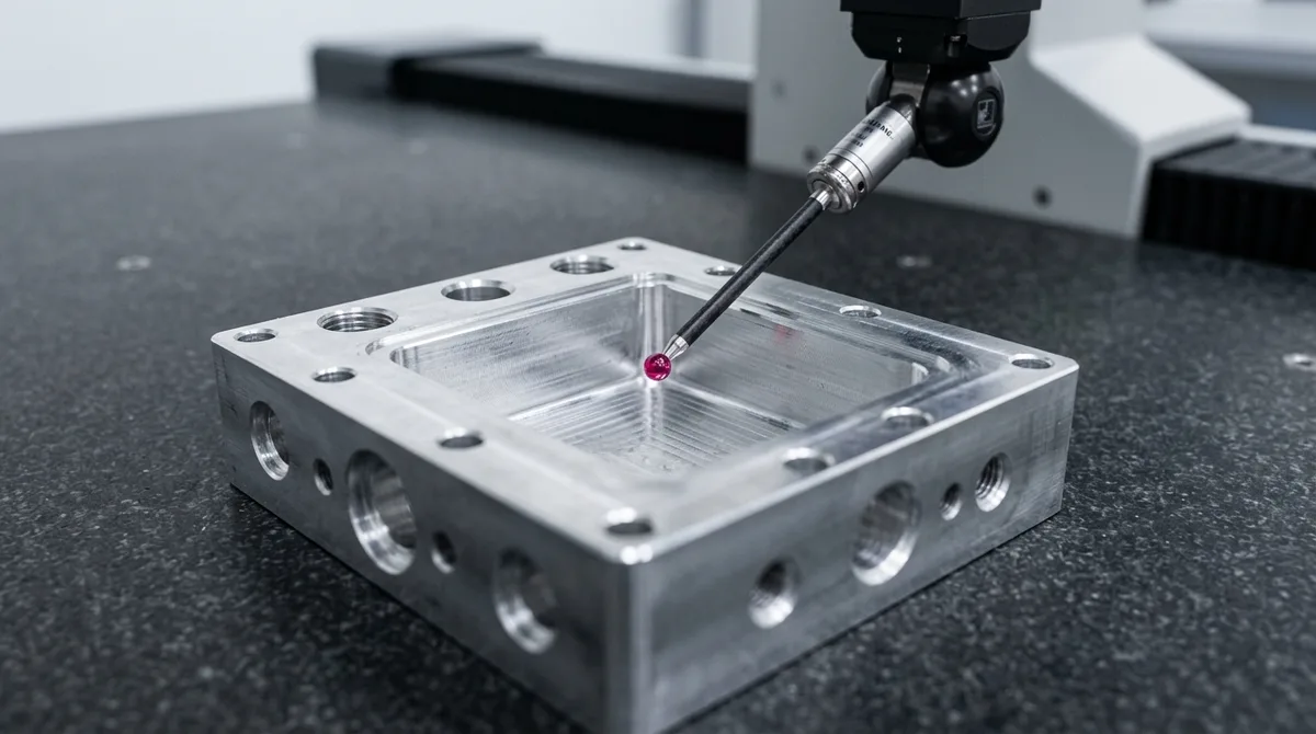
1. Tactile CMM Probing and Scanning
In our climate-controlled metrology laboratory (maintained strictly at 20 ± 0.5 degrees Celsius), precision milled pockets undergo automated tactile inspection on bridge coordinate measuring machines (CMM). A motorized indexing probe head maneuvers a slender carbon-fiber stylus fitted with a micro-ruby spherical ball tip (Ø 0.5 mm to Ø 1.5 mm).
The CMM executes continuous tactile scanning along the vertical corner wall, capturing hundreds of measurement points across the arc. Metrology algorithms calculate:
- True Radius Fit: Verifying that the finished fillet conforms to the nominal CAD radius within allowable bilateral tolerances (±0.020 mm).
- Perpendicularity to Datum A: Ensuring the vertical corner axis remains strictly perpendicular to the primary pocket floor datum within 0.015 mm.
- Runout and Form Error: Detecting harmonic wave scallops or tool deflection tapers caused by excessive corner cutting forces.
2. Optical Video Measuring Systems (VMM) and Comparators
For micro-milled features, shallow pockets, and wire EDM die openings, optical video measuring systems (VMM) provide non-contact inspection. High-resolution telecentric zoom optics project the corner profile onto an optical sensor under top and bottom LED illumination. Automated edge-detection software fits a geometric circle to the optical contrast boundary, measuring radius, corner angles, and undercut depths down to sub-micron repeatability.
3. Functional Go / No-Go Hardened Plug Gauges
For high-volume production runs involving dogbone and T-bone pockets, functional physical verification remains the most dependable shop-floor test. Precision toolmakers grind hardened Class X gauge blocks matching the maximum material condition (MMC) of the mating square component. The inspector inserts the square gauge block into the relieved pocket. If the block seats fully against all reference walls without rock or bind, the relief geometry is verified for functional assembly.
Design for Manufacturing (DFM) Rules for Machined Pockets
To balance structural rigidity, aesthetic fit, and cost efficiency, product designers should adopt the following eight practical DFM rules when drafting CNC machined pockets:
- Make Internal Radii Larger than Cutter Radii: Always specify a pocket corner radius at least 10% to 15% larger than the finishing tool radius. For an intended Ø 6.0 mm cutter (r = 3.0 mm), specify an R 3.5 mm fillet. This allows smooth circular interpolation without engagement force spikes.
- Maintain Depth-to-Radius Ratio Below 6:1: Keep cavity depth within six times the internal corner radius (Depth / R ≤ 6:1), which corresponds to a cutter aspect ratio of L/D ≤ 3:1. Exceeding this threshold exponentially increases tool deflection and machining cycle time.
- Standardize Radii Across the Part: Use identical fillet radii for all internal corners, vertical walls, and cavity boundaries across the component. Standardized radii enable a single finishing end mill to complete the entire part in one setup, eliminating tool change cycles.
- Separate Floor Radii from Vertical Wall Radii: The vertical wall corner radius is formed by the cylindrical side of the cutter, whereas the floor-to-wall radius is formed by the cutter nose corner. Specify a small floor fillet (R 0.5 mm to R 1.0 mm) or flat floor with an edge break, allowing the machinist to use a bull-nose end mill for maximum flute rigidity.
- Deploy Dogbone or T-Bone Reliefs for Square Fits: If square mating blocks must seat flush, design dogbone or T-bone undercuts directly into the CAD model rather than specifying impossible 90-degree sharp corners.
- Chamfer the Male Component: Whenever feasible, apply a 45-degree chamfer or generous radius to the male mating part. Modifying the male part is often substantially cheaper than adding corner relief operations to the female pocket.
- Reserve Wire and Sinker EDM for Hardened Steels: Only mandate sharp internal corners (R ≤ 0.05 mm) when functional necessity demands it, such as in hardened punch dies, optical apertures, or critical hydraulic valves.
- Consult Machining Engineers Early in DFM: Submitting 3D CAD models for early DFM review ensures that pocket depths, cutter clearances, and corner geometries are optimized before cutting metal, preventing expensive tooling revisions.
Frequently Asked Questions
Standard CNC milling uses cylindrical cutting tools that rotate around a central spindle axis. Because the cutting flutes sweep a circular arc, the tool naturally leaves a concave fillet radius equal to the cutter radius (R = D/2). Creating a zero-radius internal corner requires non-rotary processes such as Wire EDM, Sinker EDM, or broaching.
Designing a corner radius slightly larger than the cutting tool radius allows the toolpath to execute a smooth circular interpolation arc rather than coming to an abrupt dead stop. This continuous rolling motion prevents radial tool engagement from surging to 180 degrees, eliminating chatter, tool deflection, and premature cutter breakage.
Dogbone undercuts extend diagonally along the 45-degree corner bisector into the corner vertex, providing symmetric clearance and uniform stress distribution. In contrast, T-bone undercuts extend along only one straight wall edge, keeping the perpendicular wall unbroken so reliefs can be concealed under mating cover plates.
Wire EDM uses a continuous micro-diameter brass wire to erode conductive materials. Standard 0.25 mm wire produces internal corner radii between R 0.14 mm and R 0.16 mm, while fine micro-wire setups (0.05 mm wire) can achieve microscopic corner radii down to R 0.03 mm with precision tolerances of ±0.005 mm.
Optimize Your CNC Pocket Designs with Precision DFM Feedback
AS Prototypes delivers high-precision CNC milling, turning, and Wire/Sinker EDM machining for custom prototypes and production volumes. Our engineering team evaluates your CAD models, internal radii, and corner relief geometries to maximize part performance and lower machining costs.
Upload CAD Files for 24h DFM Review & Quotation →






