Sheet metal enclosures, electronics server chassis, and precision brackets require uncompromising dimensional accuracy across multi-stage press brake forming operations. However, metal elasticity, directional grain anisotropy, and tooling clearances inherently generate angular springback, corner tearing, and flange distortions.
Executing precision sheet metal forming requires mastering material deformation physics, calculating empirical bend deductions, selecting matched tooling sets, and designing robust relief geometry.
When forming cold sheet alloys, fibers along the exterior radius undergo intense tensile elongation, while interior fibers experience severe plastic compression. The transition boundary between tension and compression defines the neutral axis, which shifts toward the inner bend surface as deformation progresses.
Engineering Takeaway (BLUF):
Precision sheet metal forming requires calculating custom Bend Deductions (BD) using physical test coupons rather than generic CAD defaults. Always maintain minimum bend radii equal to or greater than material thickness (R ≥ T), place hole edges at least 3T + R away from bend tangent lines, cut engineered rectangular corner reliefs to isolate intersecting stress fields, and account for alloy-specific springback (0.5° to 5.0°) through CNC acute air bending with dynamic crowning compensation.
At AS Prototypes, our fabrication plant delivers verified precision sheet metal fabrication. We operate multi-axis CNC press brakes, precision fiber lasers, and hardware insertion presses backed by full factory metrology equipment. In this engineering guide, our DFM team analyzes seven fundamental best practices to ensure tight-tolerance formed components.
- Core Focus & DFM Scope: Actionable shop-floor engineering guidelines for precision sheet metal forming, covering material selection, geometric tolerancing, and defect prevention.
- Cutting & Forming Precision: Fiber laser and abrasive waterjet profiles hold ±0.05 to ±0.10 mm (±0.002″ to ±0.004″); CNC press brake flanges hold ±0.15 mm (±0.006″) and ±0.5° angular accuracy per DIN 6935.
- Edge Quality & Material Gauge: Burr-free nitrogen-assisted laser edges and zero-HAZ cold waterjet kerfs across 0.5 mm (24 Ga) to 50 mm (2.0″) gauges in aluminum, stainless steel, carbon steel, and copper.
- K-Factor & Flat-Pattern DFM: Empirical bend deduction calibration (K = 0.33–0.44) with grain-direction stress relief to prevent flange cracking and springback drift.
- Ex-Factory Turnaround: 4 to 8 business days for laser/waterjet cut and bent sheet metal prototypes; 7 to 12 business days with powder coating, anodizing, or PEM hardware insertion (excluding 3–5 days air transit).
1. Calibrating K-Factor, Bend Allowance (BA), and Bend Deduction (BD)
Calculating accurate flat blank layouts prior to laser cutting or turret punching depends directly on the material K-factor. The K-factor represents the mathematical ratio of the neutral axis location (t) relative to the total sheet thickness (T):
K = t / T (where 0.30 ≤ K ≤ 0.50)
During air bending, tensile strain along the convex exterior forces the neutral axis inward. Consequently, standard engineering calculations determine the developed Bend Allowance (BA) along the neutral arc using the following formulation:
BA = (π / 180) × (R + K × T) × θ
Here, R represents the inside bend radius, T is material thickness, and θ is the bend angle (the angle the flange is turned through, 90° for an L-bend) in degrees. To calculate the exact flat blank dimension across an exterior flange dimension, CAM programmers establish the Bend Deduction (BD) by subtracting the bend allowance from twice the Outside Setback (OSSB):
OSSB = tan(θ / 2) × (R + T)
BD = 2 × OSSB − BA
Relying on generic 3D CAD default K-factors (such as K = 0.50) creates compounding dimensional errors across multiple consecutive bends. On an enclosure with six sequential bends, a 0.20 mm calculation error per bend accumulates into an unacceptable 1.20 mm overall tolerance stack-up. Therefore, our engineering team calibrates empirical bend deduction tables using physical test coupons sheared from the specific mill heat lot.
| Alloy & Temper | Sheet Thickness (T) | Typical K-Factor | Air Bend V-Die Width | Minimum Inside Radius (R) | Springback Behavior |
|---|---|---|---|---|---|
| Aluminum 5052-H32 | 1.0 mm to 3.0 mm | 0.40 – 0.42 | 6T to 8T | 1.0 × T | Moderate (1.5° – 2.5°) |
| Stainless Steel 304 (2B) | 0.8 mm to 2.5 mm | 0.42 – 0.45 | 8T to 10T | 1.5 × T | High (3.0° – 5.0°) |
| Cold Rolled Steel (SPCC) | 1.0 mm to 3.2 mm | 0.44 – 0.46 | 6T to 8T | 1.0 × T | Low (0.5° – 1.5°) |
| Aluminum 6061-T6 | 1.2 mm to 2.5 mm | 0.38 – 0.40 | 8T to 12T | 2.5 × T to 3.0 × T | High (Severe cracking risk) |
| Copper C1100 (ETP) | 1.0 mm to 4.0 mm | 0.42 – 0.44 | 6T to 8T | 1.0 × T | Very Low (≤ 1.0°) |
2. Controlling Angular Springback and Machine Bed Deflection
Every cold formed sheet metal alloy exhibits elastic recovery upon release of forming tonnage. The degree of angular springback depends directly on the material ratio of yield strength to elastic modulus (σy / E). Austenitic stainless steel 304 work-hardens rapidly during bending, producing 3.0° to 5.0° of angular springback, whereas ductile SPCC cold rolled steel exhibits only 0.5° to 1.5°.
Air bending provides the most agile and controllable forming methodology for precision prototypes and low-to-medium production runs. In air bending, the punch nose penetrates the V-die opening without bottoming out against the die walls. Consequently, press brake operators compensate for springback by driving the punch past the target 90-degree angle (for example, forming to 86 degrees) so the flange relaxes to a precise 90.0°.
Multi-axis CNC press brakes utilize precision ground solid tool-steel punch segments descending into hardened V-dies to maintain exact bend depths. Precision backgauges automatically index sheet position along X, R, and Z axes, ensuring flawless flange alignment across single sheet blanks.
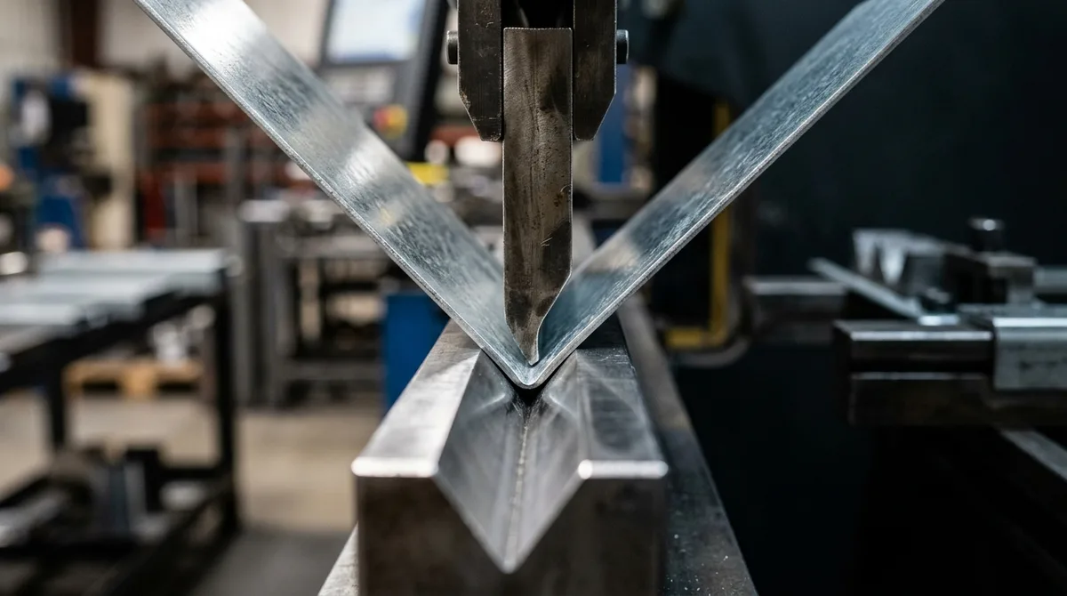
Along wide parts exceeding 500 mm in bend length, mechanical machine deflection creates the notorious canoe effect, where flanges are over-bent near the side housings and under-bent in the center. To eliminate this distortion, modern CNC press brakes incorporate dynamic hydraulic or mechanical crowning systems in the lower bed.
These crowning systems apply calculated upward counter-deflection during the stroke, ensuring uniform punch penetration depth across the entire workpiece length. Backgauge fingers equipped with optical contact sensors verify that sheet blanks seat squarely prior to tonnage execution.
3. Safe Hole-to-Bend Clearances and Feature Spacing Rules
Locating punched or laser-cut mounting holes, slots, or louvers too close to a bend tangent line induces severe localized distortion. During bending, material within the plastic deformation zone stretches non-linearly, pulling circular holes into distorted ellipses and tilting critical fastener axes out of perpendicularity.
The plastic deformation zone extends outward from the tangent bend line by a distance proportional to sheet thickness and inside bend radius. To maintain true hole roundness and positional accuracy, design engineers must observe the fundamental geometric clearance rule:
Minimum Distance (Hole Edge to Bend Tangent) ≥ 3T + R
When physical packaging constraints force mounting holes closer than 3T + R, engineers must integrate transverse laser-cut relief slots between the hole and the bend tangent line. These narrow relief slots absorb localized plastic strain during bending, preventing deformation forces from transferring to the mounting feature.
Countersunk holes and extruded tapped holes require even greater isolation clearances. Countersinking removes critical surface material, concentrating tensile stresses that readily crack if located inside the plastic flow zone. Maintain a clearance of at least 4T + R between countersink outer chamfer edges and adjacent bend tangent lines.
4. Engineering Bend Relief Notches and Minimum Flange Lengths
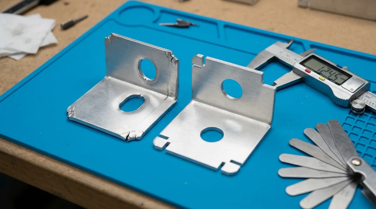
When two adjacent flanges bend along intersecting axes (such as four-sided chassis boxes or deep electronic enclosures), the metal at the corner intersection experiences severe triaxial stress concentrations. Without engineered corner relief cutouts, intersecting metal stretches, bunches, and tears jaggedly across the corner seam.
To ensure clean, crack-free corner geometry and smooth welded seams, laser programmers incorporate rectangular, circular, or teardrop relief notches directly into the flat blank pattern prior to forming. The minimum dimensions for corner relief notches are governed by sheet thickness and inside radius:
Relief Notch Width (w) ≥ T (minimum 1.5 mm)
Relief Notch Depth (d) ≥ R + T
Equally critical is maintaining a viable minimum flange length (B). During air bending, the workpiece must bridge across both shoulders of the lower V-die without slipping prematurely into the die opening. If a flange is designed too short, the workpiece slips off the die shoulder mid-stroke, producing erratic bend angles and damaging tooling.
| Design Feature | Minimum Dimension Rule | Physical Defect if Violated | Recommended DFM Correction |
|---|---|---|---|
| Minimum Flange Length | B ≥ 4T + R | Sheet slips into V-die opening | Extend flange length or select specialized acute offset tooling. |
| Hole-to-Bend Distance | Distance ≥ 3T + R | Hole stretches into egg shape | Shift hole location or add laser-cut strain relief slots. |
| Corner Bend Reliefs | Depth ≥ R + T, Width ≥ T | Corner metal tears and tears open | Incorporate laser-cut rectangular or keyhole corner notches. |
| Slot-to-Bend Distance | Distance ≥ 4T + R (parallel) | Slot edges bow and distort | Orient slots perpendicular to bend line or increase margin. |
| Rolling Grain Direction | Form perpendicular to grain | Brittle outer surface cracking | Rotate blank nesting layout 45° or 90° relative to coil grain. |
Furthermore, sheet metal coils possess distinct directional rolling grain from the steel or aluminum rolling mill. Forming parallel to sheet rolling grains severely increases outer fiber cracking susceptibility, particularly in high-strength alloys like Aluminum 6061-T6 and cold-rolled stainless steel. Whenever possible, CAM nesting routines orient primary bend axes perpendicular (or at minimum 45 degrees) to the material grain direction.
5. Flange Hemming, Curls, and Edge Stiffening Design
Thin sheet metal structures often require superior edge stiffness and ergonomic safety without adding secondary reinforcing gussets or external stiffeners. Hemming folds the edge of a sheet metal blank back over itself 180 degrees, creating a robust, dual-thickness safety edge that dramatically increases section modulus and torsional rigidity.
Depending on material ductility, forming engineers deploy three primary hemming profiles:
- Teardrop Hem: The return flange forms a smooth, circular loop before resting against the base sheet. This profile avoids tight-radius coining, making it ideal for non-heat-treatable aluminum alloys like 5052-H32 and work-hardening stainless steels.
- Open Hem: A small internal gap (typically equal to material thickness, g ≈ T) remains between the hemmed flap and the parent sheet. Open hems accommodate heavy powder coat finishes and provide channels for sealing gaskets.
- Closed (Flat) Hem: The return flange is fully flattened flush against the parent sheet. Flat hems require high material ductility, such as low-carbon SPCC or annealed deep-drawing steels, as tighter radius coining can crack less ductile alloys.
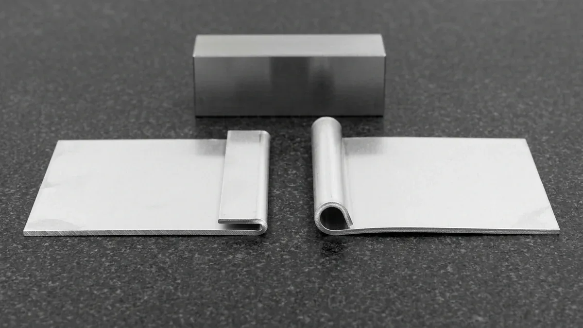
Executing precision hems requires a two-stage forming process. In the first stroke, an acute 30-degree punch forms a preliminary sharp pre-bend. In the second stroke, a flattening die (hemming tool) compresses the return flange down to the desired final hem opening.
For tubular wire-routing passages and structural outer lips, sheet metal curls roll the sheet edge into a complete circular tube (360 degrees). Curls require an inside radius of at least 1.5T to 2.0T to prevent localized split fractures along the outer tensile skin.
6. Self-Clinching PEM Fasteners and Hardware Insertion Integration
Directly tapping screw threads into sheet metal below 2.0 mm thickness yields inadequate thread engagement, typically resulting in fewer than three full load-bearing threads. Stripped threads under operating torque present severe reliability risks in field environments.
Self-clinching fasteners (commonly known as PEM hardware) provide permanent, high-strength female threads, male studs, and standoffs in thin metal sheets. During installation on hydraulic insertion presses, controlled squeeze force drives the fastener clinching ring into a pre-pierced sheet hole. The cold metal displaces plastically into an annular undercut recess around the fastener shank, locking it permanently with exceptional push-out and torque-out resistance.
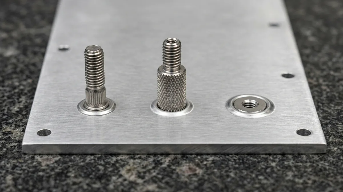
To ensure flawless clinch hardware integration, mechanical engineers must follow strict DFM insertion guidelines:
- Hole Diameter Tolerances: Laser-cut or CNC punched mounting holes must be held to tight limits (+0.08 / -0.00 mm). Oversized holes reduce material displacement into the undercut ring, causing loose hardware, while undersized holes deform the sheet face.
- Edge Distance Clearances: Position clinch fastener centers at least 1.5 times the fastener shank diameter from raw sheet edges. Squeezing fasteners too close to edges causes localized sheet bulging along the perimeter.
- Bend Line Interference: Clinch hardware must sit safely beyond the punch contact zone. Maintain a minimum distance of 3T + R between fastener flanges and bend lines to prevent press brake tooling collisions.
- Material Hardness Matching: Fasteners must be significantly harder than the host sheet metal. For stainless steel 304 panels, use precipitation-hardened stainless steel clinch hardware (such as A286 or 400-series alloy) to achieve proper cold-flow lock.
Whenever geometry permits, inserting clinch hardware into flat blanks prior to press brake forming optimizes throughput. However, if return flanges or tall upright channels obstruct hydraulic ram tooling access during post-bend assembly, sequencing insertion before bending is strictly mandatory.
7. Precision Metrology, Inspection Standards, and Quality Verification
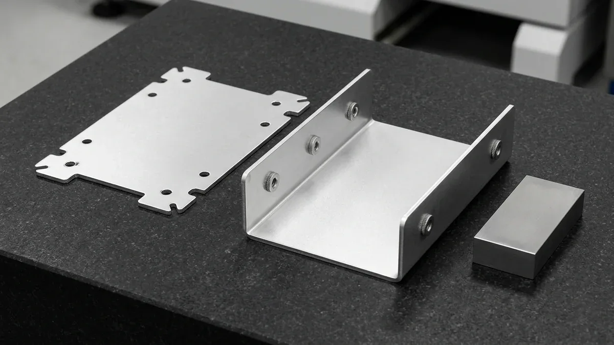
Validating precision sheet metal assemblies requires multi-axis metrology protocols conducted on Grade 00 black granite surface plates. Unlike rigid CNC machined blocks, formed sheet metal features slight elastic flexibility that demands precise datum referencing during geometric dimensioning and tolerancing (GD&T per ASME Y14.5) inspection.
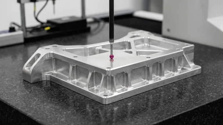
Inspectors utilize coordinate measuring machines (CMM) and optical comparators to verify overall enclosure heights, step flange elevations, and hole pattern locations relative to the primary datum plane. A motorized CMM touch-trigger probe with a ruby ball stylus maps surface profile tolerances and hole perpendicularity across all formed planes.
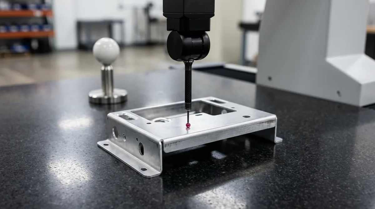
Our quality control laboratory applies rigorous dimensional verification across all production stages:
- General Tolerances: Unspecified dimensions adhere to ISO 2768-mK baseline standards (linear dimensions ±0.10 mm to ±0.50 mm for nominal lengths up to 400 mm; angular tolerances ±1° down to ±10′ depending on shorter leg length).
- Precision Flange Heights & Centers: Critical mating features and CNC machined secondary interfaces are held to ±0.05 mm to ±0.10 mm through calibrated press brake backgauges and laser-cut pilot holes.
- CMM Coordinate Scanning: For complex aerospace brackets and automotive chassis weldments, our Zeiss coordinate measuring machines (CMM) probe hole patterns, profile of a surface tolerances, and perpendicularity datums.
- Environmental Corrosion Testing: Formed enclosures undergoing post-processing (such as MIL-A-8625 Type II anodizing, zinc electroplating, or epoxy powder coating) undergo ASTM B117 neutral salt spray corrosion testing (24h to 240h) to confirm environmental barrier integrity.
- Hardness Verification: Host sheet alloys and cold-worked bend zones are verified via ASTM E18 Rockwell or ASTM E384 Vickers micro-indentation hardness testing.
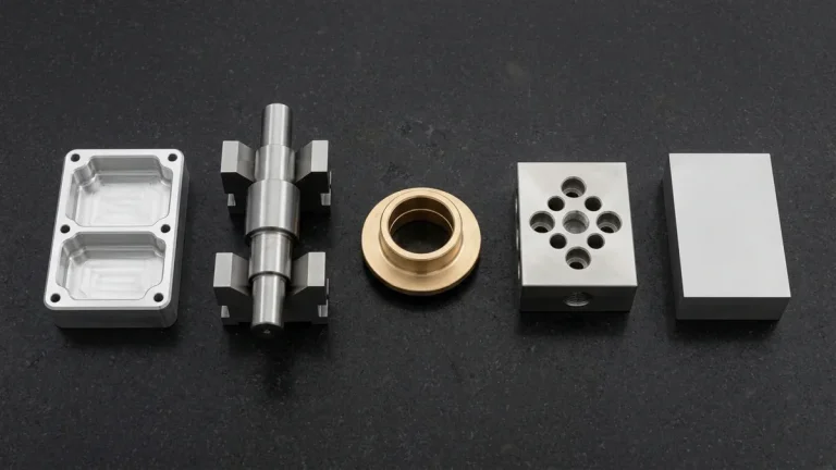
In addition to our dedicated sheet metal capabilities, our facility integrates precision CNC machining services for complex milled enclosures, turned hardware bushings, and precision hybrid weldments.
Outer fiber cracking occurs when the inside bend radius is smaller than the alloy minimum allowable bend radius, or when bending parallel to sheet rolling grains. High-strength alloys like 6061-T6 require a minimum inside radius of 2.5T to 3.0T and should be formed perpendicular to the coil grain direction.
Austenitic stainless steel 304 work-hardens rapidly during forming and exhibits a high yield strength to modulus ratio, producing 3.0 to 5.0 degrees of angular springback. In contrast, ductile aluminum 5052-H32 exhibits moderate springback of 1.5 to 2.5 degrees, requiring less punch overbending.
When two adjacent flanges bend along intersecting axes, their plastic deformation zones collide. Without engineered rectangular or circular corner relief notches, the intersecting metal bunches and tears open. Corner reliefs isolate the deformation zones, ensuring clean corners and sound welded seams.
Self-clinching fasteners should typically be pressed into bare metal prior to powder coating to ensure electrical grounding and prevent coating chipping around the clinch ring. For anodized aluminum, fasteners can be installed after anodizing if using compatible stainless steel hardware and clean press fixturing.
Need Precision Formed Sheet Metal Parts and Enclosures?
AS Prototypes delivers high-precision fiber laser cutting, multi-axis CNC press brake forming, PEM hardware insertion, and robotic seam welding. Upload your 3D CAD models today for expert DFM bend analysis and comprehensive engineering review within 24 hours.
Upload CAD for Sheet Metal DFM Review →