

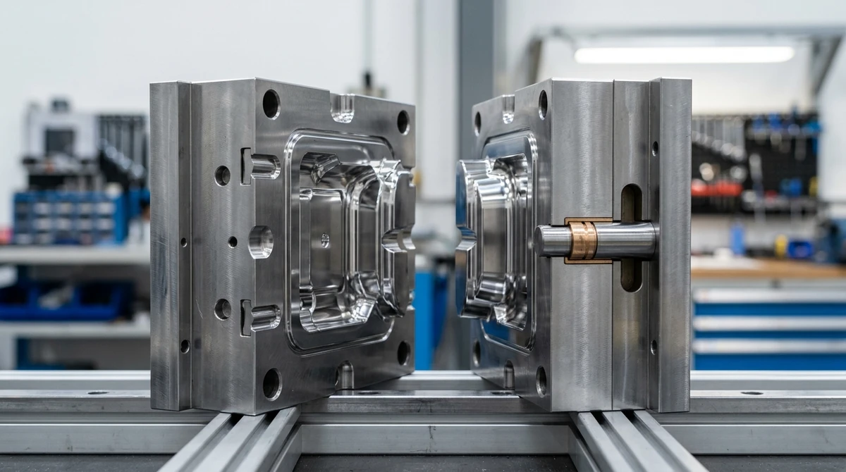
Quick Engineering Takeaways (BLUF)
Core Tooling Classification: The mold making process spans SPI/SPE Class 101 ultra-high-volume hardened tools (1,000,000+ cycles) down to Class 105 prototype unit dies (≤500 cycles), dictating distinct metallurgy, runner architecture, and cooling circuit integration.
Metallurgy & Thermal Transfer: Pre-hardened P20 (28–34 HRC) and NAK80 (38–42 HRC) serve structural and medium-run production, while vacuum-hardened H13 (48–52 HRC) and corrosion-resistant S136/420 ESR (48–54 HRC) withstand abrasive glass-filled and corrosive resins. Beryllium copper (CuBe) inserts resolve localized hotspot heat bottlenecks.
Subtractive & Non-Traditional Synergy: 3-axis and 4-axis CNC vertical machining centers (VMCs) handle 75%–85% of plate hogging, pockets, and waterlines, while high-speed 5-axis centers contour complex 3D parting lines. Sinker EDM (die sinking) and slow wire EDM (WEDM) produce micro-fine ribs, sharp corners, and ejector guideways with ±0.010 mm (sinker EDM) to ±0.005 mm (slow wire EDM) accuracy.
Lead Time & Turnaround Benchmark: Design for Manufacturing (DFM) and quotation feedback are delivered within 24 hours. Rapid tooling and T1 sample tryout are completed in 18 to 35 business days (ex-factory production turnaround), followed by comprehensive Zeiss coordinate measuring machine (CMM) dimensional qualification.
The mold making process represents the critical foundation of modern polymer component manufacturing, directly dictating final part repeatability, production cycle efficiency, and cosmetic excellence. For hardware product designers, mechanical engineers, and procurement specialists, tooling fabrication is an intricate transition where digital 3D CAD models become hardened, multi-ton mechanical assemblies capable of withstanding dynamic hydraulic clamping pressures exceeding hundreds of metric tons. Every micrometric decision—from the thermal conductivity of the tool steel to parting line shut-off angles—imposes physical boundaries on cycle time, dimensional stability, and tooling longevity.
Successfully executing an injection mold project requires tight integration between upfront polymer rheology simulation, advanced subtractive CNC milling, precision electrical discharge machining (EDM), meticulous manual benching, and scientific molding validation. Without rigorous upfront Design for Manufacturing (DFM) verification, minor geometric oversights like inadequate draft angles or unbalanced wall transitions trigger catastrophic tooling failures, including severe sink marks, parting line flash, differential shrinkage warpage, or premature tool steel fatigue. This engineering guide examines the complete end-to-end tooling workflow, delivering actionable parameters and shop-floor insights to guarantee precision manufacturing outcomes.
1. SPI Tooling Classifications & Architecture Standards
Before selecting tool steels or programming CNC toolpaths, tooling engineers must align mold architecture with anticipated lifetime production volumes. The Society of the Plastics Industry (SPI, now PLASTICS) established standardized tooling classifications (Class 101 through Class 105) to eliminate discrepancies between part buyers and moldmakers regarding structural rigidity, steel grades, thermal management, and guided ejection requirements.
A Class 101 production mold is engineered for extreme longevity, guaranteed for over 1,000,000 cycles. These tools require through-hardened cavity and core inserts (minimum 48 HRC), guided ejection systems, hardened slide wear plates, temperature regulation lines embedded in all moving cores, and corrosion-resistant plating across internal cooling circuits. Conversely, Class 104 and 105 molds serve low-volume bridge production and rapid prototype validation, utilizing pre-hardened steels (P20) or high-strength aircraft-grade aluminum (7075-T651) housed within modular Master Unit Die (MUD) frames to drastically curtail upfront tooling lead times.
Clamping Force and Mechanical Load Mechanics
During the high-pressure injection stage, molten polymer enters the mold cavity at pressures typically ranging from 300 to 1,200 bar (4,350 to 17,400 psi). This internal fluid pressure exerts an enormous separating force along the parting line. Tool designers calculate the required machine clamping tonnage using the projected surface area of the molded parts and runner channels:
F_clamp = (P_cavity × A_projected × S_safety) / 1,000In this mechanical equilibrium model, F_clamp represents total machine clamping force in metric tons, P_cavity is the average peak cavity pressure in bar (dependent on polymer melt viscosity and flow length-to-thickness ratio), A_projected denotes total projected surface area in square centimeters perpendicular to the parting line, and S_safety is an essential safety multiplier (typically 1.15 to 1.25). If mold plates lack sufficient thickness, backing pillar support, or heel block rigidity, cavity deflection exceeding 0.020 mm will breach the parting line seal, generating severe flash and damaging the shut-off surfaces.
2. Upfront DFM Analysis & Rheological Gating Architecture
Every tooling program initiated at AS Prototypes begins with a rigorous, upfront Design for Manufacturing (DFM) evaluation. Tooling engineers review 3D CAD geometry to identify moldability bottlenecks before cutting any metal. Primary DFM checkpoints include nominal wall thickness consistency, corner transitions, draft angle distribution, parting line orientation, side-action undercuts, and gate placement.
Wall thickness variations represent the most common cause of molded part rejection. When a molten resin cools within the mold, thick sections dissipate heat significantly slower than thin walls, generating differential volumetric shrinkage. This thermal imbalance induces localized tensile residual stresses that pull the outer surface inward, forming cosmetic sink marks or causing severe part warpage. Applying core-out geometries and transitioning uneven walls with gradual 3:1 blending tapers eliminates localized stress concentrations and guarantees uniform melt front advancement.
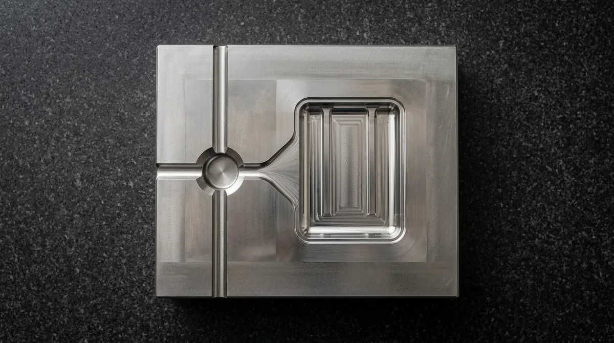
As illustrated in the precision CNC-machined mold cavity insert above, runner layout and gating architecture govern how polymer enters the mold. The cold slug well situated at the runner intersection captures the initial, chilled polymer skin that forms as molten resin travels through the machine nozzle, preventing solidified resin from blocking delicate gate orifices. A flared fan gate provides a wide, controlled transition zone, minimizing polymer shear heating and eliminating flow hesitation lines across large cosmetic surface panels.
Draft Angles and Mold-Tech Texture Guidelines
Draft angles are non-negotiable geometric tapers applied to all vertical part faces oriented parallel to the mold opening direction. As polymer cools inside the cavity, it shrinks away from outer cavity walls while clinging tightly to internal steel cores. Without adequate draft, the mechanical drag friction during ejection causes severe scuffing, stress whitening, or pin push-through pin eject marks. Smooth, mirror-polished surfaces (SPI A-1 to A-3) operate reliably with a minimum of 0.5° to 1.0° draft per side, whereas standard machine-milled textures demand 1.5° to 2.0°.
When engineering components require chemical-etched textures—such as Mold-Tech (MT) or VDI 3400 spark erosion finishes—draft angles must increase proportionally to avoid shearing the microscopic grain peaks during mold opening. Toolmakers apply the empirical draft guideline:
Draft_required = 1.0° + (Texture Depth / 0.025 mm) × 1.0°For example, a light leatherette texture with a grain depth of 0.050 mm (0.002 in) mandates a minimum draft angle of 3.0° per side. If the part features steep vertical side walls that cannot accommodate this draft, sliding side-action mechanisms or expanding cavity splits must be engineered into the mold architecture to retract perpendicular to the part before mechanical ejection begins.
Undercut Mechanisms: Slides, Lifters & Pick-Outs
Features such as external snap-fit tabs, side holes, internal latch catches, or perimeter threads prevent straightforward two-plate mold separation. Tooling designers implement specialized mechanical kinematic solutions based on production volume and part geometry:
- Cam-Driven Sliding Side-Actions (Slides): Hardened angle pins (horn pins) mounted to the stationary cavity half mechanically drive side slide blocks outward as the mold opens. Rigid heel blocks angled 2° to 3° steeper than the guide pin clamp the slide against cavity injection pressures during the shot.
- Angled Ejector Lifters: Internal undercut features—such as inward-facing snap hooks—rely on ejector-driven lifters mounted on universal swivel joints. As the ejector plate moves forward, the lifter travels upward and inward simultaneously, clearing the undercut before part drop.
- Hand-Loaded Loose Cores (Pick-Outs): For low-volume bridge tooling and complex rapid prototypes, dual-station hand-loaded aluminum or steel inserts are manually placed into the mold before injection, ejected with the part, and demolded on an adjacent bench fixture to eliminate costly motorized slide cams.
3. Tool Steel Metallurgy & Thermal Management Physics
Tool steel metallurgy directly dictates tooling longevity, polishability, thermal cycle speed, and resistance to chemical erosion. Selecting the optimal alloy involves balancing raw material costs and machining machinability against expected production cycles and resin abrasiveness.
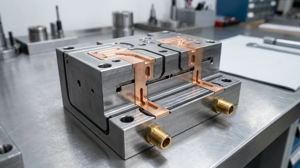
As highlighted in the mold core assembly above, managing thermal dissipation in deep ribs and slender core pins presents a severe engineering challenge. Conventional tool steels possess relatively modest thermal conductivity (P20 provides ~29 W/m·K, while H13 delivers ~24 W/m·K). When molten resin wraps around a slender steel core, localized heat accumulates rapidly, causing resin degradation, burn marks, and prolonged cooling cycles. Press-fitting high-conductivity copper alloys—such as Beryllium Copper C17200 (105–130 W/m·K) or Ampcoloy—draws thermal energy directly into internal water circuits, slashing overall cycle times by 25% to 40%.
Heat Transfer and Cooling Time Physics
Cooling represents between 60% and 80% of the entire injection molding cycle. Minimizing cooling duration without triggering thermal warpage is essential for cost-effective manufacturing. Tooling engineers model cooling time using the one-dimensional unsteady-state Fourier heat conduction equation:
tcool = (h2 / (π2 × α)) × ln((4 / π) × ((Tmelt – Tmold) / (Teject – Tmold)))In this thermal governing relationship, h represents nominal part wall thickness in millimeters, α is polymer thermal diffusivity (defined as thermal conductivity divided by the product of density and specific heat capacity: k / (ρ × C_p)), while Tmelt, Tmold, and Teject denote melt injection temperature, mold tool surface temperature, and ejection demolding temperature, respectively. Because wall thickness h is squared in the numerator, doubling part wall thickness quadruples required cooling time. Meticulous conformal cooling channel design and optimized water baffle placement ensure uniform heat extraction across both core and cavity plates.
Vacuum Heat Treatment & Cryogenic Stabilization
High-wear steels like AISI H13 and S136 stainless steel arrive in an annealed condition (20–24 HRC) to facilitate rough CNC milling. Following semi-finish machining, cavity and core blocks undergo vacuum furnace heat treatment: gradual pre-heating to 850°C, high-temperature austenitizing at 1,020°C–1,040°C, and nitrogen gas quenching under 5 to 6 bar pressure to transform austenite into martensite.
Crucially, high-precision molds undergo double tempering (520°C–560°C) followed by sub-zero cryogenic stabilization (-120°C to -196°C). Cryogenic treatment forces unstable retained austenite to fully transform into hard martensite, preventing microstructural phase shifts that cause unprovoked dimensional creeping or warping after hundreds of thousands of high-clamping cycles. The resulting matrix achieves a uniform 48 to 54 HRC with high fracture toughness.
| Tooling Alloy Grade | Hardness (HRC) | Thermal Conductivity (W/m·K) | Polishability (SPI Standard) | Corrosion Resistance | Guaranteed Tool Life | Recommended Polymer Applications |
|---|---|---|---|---|---|---|
| Aluminum 7075-T651 | ≈ 87 HRB (150 HB) | 130 | SPI B-1 / A-3 | Low (Anodize sealed) | 10,000 – 50,000 shots | Rapid prototypes, PP, PE, ABS, bridge production validation |
| Pre-Hardened P20 (1.2311) | 28 – 34 | 29 | SPI B-1 / A-3 | Moderate | 50,000 – 300,000 shots | SPI Class 103 medium-volume consumer electronic enclosures |
| NAK80 (Age-Hardened) | 38 – 42 | 41 | SPI A-1 (High Mirror) | Moderate | 250,000 – 500,000 shots | High-finish transparent lenses, light guides, PMMA, PC |
| Through-Hardened H13 | 48 – 52 | 24 | SPI A-2 | Good | 500,000 – 1,000,000 shots | Abrasive glass-filled resins (PA66-GF30, PBT-GF), structural parts |
| Stainless S136 / 420 ESR | 48 – 54 | 20 | SPI A-1 (Optical Diamond) | Superior | 1,000,000+ shots | Medical disposables, optical housings, corrosive resins (PVC, POM) |
| Beryllium Copper (CuBe) | 36 – 40 | 115 | SPI B-2 | High | 250,000 shots | Core pins, deep rib inserts, hot runner nozzle gate bushings |
4. Subtractive Machining: High-Speed CNC Milling & Gun Drilling
Modern mold making relies on high-precision subtractive machining to execute bulk stock evacuation, cooling circuits, and fine profile contouring. In our precision machine shop, 3-axis and 4-axis CNC vertical machining centers (VMCs) serve as the operational workhorses, undertaking 75% to 85% of all machining volume—including squaring raw forged blocks, rough pocket milling, ejector plates, and precision waterline manifolds.
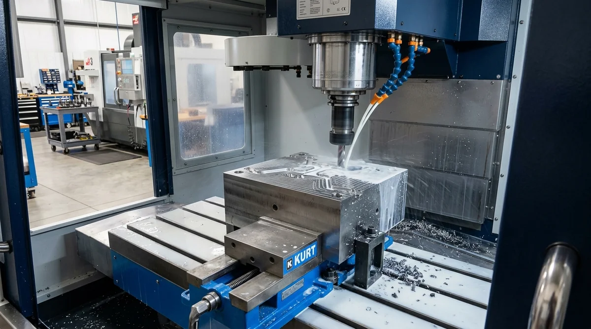
As shown in the VMC machining cell above, heavy roughing of pre-hardened P20 and annealed H13 blocks utilizes rigid indexable button cutters and high-feed mills operating under adaptive trochoidal toolpaths. Trochoidal milling maintains a constant tool engagement angle (TEA ≤ 40°), preventing radial cutter snatch and thermal shock on carbide inserts while achieving material removal rates exceeding 250 cm³/min. Following rough evacuation, tool blocks rest for 12 to 24 hours to relieve residual machining stresses before semi-finishing commences.
High-Speed 5-Axis Finish Milling & Scallop Height Control
For complex 3D sculpted part geometries, organic parting lines, and deep drafted cavities, high-speed 5-axis machining centers (operating at 20,000 to 30,000 RPM) take over the finish pass. Multi-axis simultaneous kinematics allow the cutter axis to tilt continuously relative to steep cavity walls. By maintaining a 15° to 20° lead angle, ball-nose end mills avoid the zero-surface-speed dead zone located at the absolute center tip of the ball, producing superior surface finishes down to Ra 0.4 µm.
The theoretical residual surface roughness generated by a ball-nose mill is governed by the step-over distance and cutter radius, mathematically defined as scallop height (cusp height):
h_scallop = R – √(R² – (stepover / 2)²)Where R is ball-nose cutter radius and stepover is the lateral distance between consecutive tool passes. On critical mold shut-off lands and cosmetic optical cavities, CAM programmers program ultra-fine step-over distances (0.05 to 0.10 mm), keeping scallop height below 0.001 mm. This drastic reduction in cusp height slashes subsequent manual hand-benching and polishing time by more than 60%.
Gun Drilling and Conformal Cooling Circuitry
Mold temperature uniformity dictates dimensional repeatability. CNC deep-hole gun drills bore straight cooling lines across large mold plates with length-to-diameter ratios exceeding 30:1 with minimal axial drift. Waterline diameters are standardized at 10 to 12 mm, spaced 3 to 4 diameters apart, and positioned 1.5 to 2.0 diameters beneath cavity surfaces. In complex core inserts where straight gun-drilled circuits cannot reach, toolmakers employ threaded brass baffles, cascading fountain bubblers, or direct metal laser sintered (DMLS) 3D printed maraging steel inserts with conformal cooling channels following intricate part contours.
5. Non-Traditional Machining: Die Sinking EDM & Slow Wire EDM
Despite the immense cutting power of high-speed CNC milling centers, physical rotating end mills cannot machine sharp internal 90° corners, narrow structural ribs (e.g., 0.8 mm wide with 15 mm depth), or intricate textured logos. In these geometric zones, non-traditional electrical discharge machining (EDM) is indispensable.
During precision die-sinking EDM operations, material removal occurs through controlled thermo-electric spark erosion. The workpiece (hardened tool steel) and electrode (high-density graphite or copper-tungsten) are submerged in a dielectric hydrocarbon oil or deionized water bath. When pulsed high-frequency electrical voltage breaches the dielectric insulation barrier, a plasma discharge channel generates temperatures exceeding 8,000°C to 12,000°C, instantly vaporizing microscopic steel particles. Because the electrode never physically touches the tool steel, cutting tool deflection is exactly zero.
Electrode Engineering & White Recast Layer Remediation
Precision sinker EDM relies on multi-electrode programming. A minimum of three sequential electrodes is typically deployed: a roughing electrode (spark gap overcut: 0.25 to 0.35 mm), a semi-finisher (spark gap: 0.12 to 0.18 mm), and an orbital planetary finishing electrode (spark gap: 0.03 to 0.05 mm). Ultrafine isotropic graphite grades (such as Poco EDM-3 or EDM-AF5, with grain sizes below 5 µm) are machined on dedicated high-speed CNC electrode mills equipped with sealed HEPA dust extraction.
A critical metallurgical phenomenon in spark erosion is the formation of the recast layer (often termed the “white layer”). During EDM discharge, molten steel that is not fully flushed away by dielectric fluid rapidly requenches against the cold parent metal, forming a brittle, untempered martensitic layer 2 to 10 µm thick laden with micro-cracks and residual tensile stresses. If left untreated, this brittle layer can cause fatigue spalling or premature cracking under high injection pressures. At AS Prototypes, we eliminate the recast layer using finish planetary orbital pulses, micro-glass bead blasting, or light chemical polishing prior to mold assembly.
Slow Wire EDM (WEDM) for Precision Guidance Components
Slow wire electrical discharge machining (WEDM) feeds a continuous brass or coated zinc wire (0.20 to 0.25 mm diameter) through submerged steel plates to slice complex 2D and tapered profiles with ±0.005 mm precision. WEDM is extensively used to machine ejector pin through-holes, angled lifter slide pockets, slide track gibs, and interlocking taper blocks. By maintaining clearances of 0.005 to 0.008 mm between moving ejector pins and cavity bores, the mold achieves smooth, frictionless mechanical strokes while completely preventing molten plastic from bleeding into pin clearances to form flash.
| Machining Stage | Primary Machine Tooling Cell | Machining Tolerance | Target Roughness (Ra / VDI) | Core Operational Scope |
|---|---|---|---|---|
| Mold Base Roughing | Heavy-Duty 3-Axis CNC VMC | ±0.050 mm | Ra 3.2 μm | Bulk stock hogging, pocket pockets, clamp slots, and deep gun drilling |
| Semi-Finish & Finish Milling | High-Speed 5-Axis VMC (30,000 RPM) | ±0.010 mm | Ra 0.4 – 0.8 μm | 3D contoured core/cavity surfaces, parting lands, slide locks |
| Die Sinking EDM | CNC Sinker EDM (Orbital Spark) | ±0.010 mm | Ra 0.4 – 1.6 μm (VDI 12 – 24) | Deep structural ribs, sharp 90° corners, textured cavity facets |
| Slow Wire EDM (WEDM) | Submerged Multi-Axis Wire EDM | ±0.005 mm | Ra 0.4 μm | Ejector pin guides, lifter slots, interlocking wedges, side core tracks |
| Precision Surface Grinding | CNC Precision Surface Grinder | ±0.005 mm | Ra 0.2 μm | Parting line datum plates, slide backing plates, guide pin wear gibs |
| Manual Spotting & Polishing | Experienced Bench Toolmakers | Datum Matched | SPI A-1 (Ra 0.012 μm) | Prussian blue seal matching, optical diamond paste mirror polishing |
6. Tool Assembly, Hand Spotting, Parting Line Seal & Metrology
Following CNC milling, heat treatment, and EDM spark erosion, individual mold components transition to the assembly and benching area. While computer numerical control guarantees precision down to single-digit microns, the final integration of an injection mold remains a master toolmaker’s craft. Dynamic thermal expansion, machine clamping plate deflection, and hydraulic tonnage necessitate manual spotting and fitting.
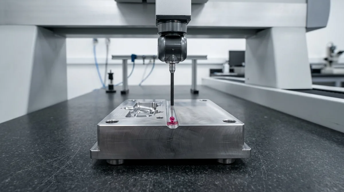
As demonstrated in the quality inspection laboratory above, toolmakers utilize Zeiss coordinate measuring machines (CMM) to verify datum planes, runner dimensions, and shut-off lands before clamp trials begin. The CMM’s high-precision ruby touch probe executes automated measurement routines across critical core-to-cavity alignment interlocks, validating profile tolerances within ±0.010 mm to prevent core shift under asymmetric injection pressures.
Prussian Blue Spotting & Parting Line Shut-Off Integrity
To eliminate parting line flash, the mating steel lands between the core and cavity halves must achieve absolute intimate contact. Technicians apply a microscopic film of Prussian blue paste (spotting ink) across the cavity shut-off lands, mount the assembly into a hydraulic spotting press, and close the mold under calculated tonnage. When the mold reopens, the transfer pattern reveals high spots and gaps.
Toolmakers delicately stone and scrape high spots until achieving greater than 85% uniform blue contact across the primary shut-off perimeter. Perimeter shut-off lands typically measure 15 to 25 mm in width; beyond this perimeter, tool steel is relieved (dropped by 0.5 to 1.0 mm) to concentrate clamping tonnage precisely where molten plastic must be sealed. Furthermore, taper interlocks and side locks mounted on the mold perimeter prevent side-to-side thermal wandering during operation.
SPI Mold Cavity Surface Finishing Standards
Depending on cosmetic and optical part specifications, tool cavity surfaces receive specialized finishing treatments standardized by the Society of the Plastics Industry (SPI):
- SPI Grade A (Diamond Mirror Polish): Applied to high-hardness steels (S136, NAK80). Technicians hand-polish surfaces using progressively finer diamond compound pastes down to 3 µm particle size (SPI A-1 produces Ra 0.012–0.025 µm), essential for optical lenses and high-gloss cosmetic fascias.
- SPI Grade B (Grit Sandpaper Polish): Finished using 320 to 600 grit silicon carbide emery paper (Ra 0.05–0.10 µm) with semi-gloss luster, ideal for eliminating tool marks while maintaining mold release lubricity.
- SPI Grade C (Fine Stone Polish): Hand-stoned with 280 to 600 grit aluminum oxide stones (Ra 0.3–0.6 µm), standard for non-cosmetic internal housings and industrial brackets.
- SPI Grade D (Dry Blast Texture): Dry blast peened with #24 aluminum oxide or glass micro-beads (Ra 0.8–2.4 µm) to produce a uniform diffuse satin texture that effectively conceals weld lines and minor sink marks.
7. Resin Shrinkage Dynamics & DFM Geometry Rules
Every thermoplastic resin undergoes volumetric contraction as it transitions from a high-temperature molten state into a cooled solid. If toolmakers fail to compensate accurately for resin shrinkage in the CAD model before machining cavity steel, the molded components will fail dimensional inspection. Shrinkage rates vary drastically based on polymer morphology—specifically whether the resin is amorphous or semi-crystalline.
Amorphous engineering polymers—such as ABS, Polycarbonate (PC), and PMMA—feature random, tangled polymer chains that exhibit low, isotropic linear (mold) shrinkage (typically 0.4% to 0.7%). In contrast, semi-crystalline polymers—such as Polypropylene (PP), POM (Acetal), and Nylon 66 (PA66)—form tightly packed crystalline spherulites upon cooling, generating substantial shrinkage rates of 1.2% to 2.5%. Furthermore, reinforcing fibers (such as 30% glass fiber) cause severe anisotropic shrinkage: shrinkage along the polymer flow orientation can drop to 0.2%, while cross-flow shrinkage remains at 0.8% to 1.0%, inducing severe twist and bowing if gating is unbalanced.
| Polymer Resin & Grade | Morphology | Nominal Wall Range (mm) | Linear Shrinkage (%) | Min. Draft Angle (Cavity/Core) | Max. Rib-to-Wall Ratio | Recommended Gate System |
|---|---|---|---|---|---|---|
| ABS (General Purpose) | Amorphous | 1.2 – 3.2 | 0.4% – 0.7% | 0.5° / 1.0° | 50% – 60% | Submarine / Edge / Fan gate |
| PC (Polycarbonate) | Amorphous | 1.5 – 3.8 | 0.5% – 0.7% | 1.0° / 1.5° | 40% – 50% | Tab / Flared Fan / Valve gate |
| PC + ABS Blend | Amorphous Alloy | 1.5 – 3.5 | 0.5% – 0.7% | 1.0° / 1.5° | 50% | Edge / Hot sprue / Sub-gate |
| PA66 + 30% GF (Nylon) | Semi-Crystalline (Filled) | 1.2 – 3.0 | 0.2% – 0.9% (Anisotropic) | 1.5° / 2.0° | 40% | Direct sprue / Heavy edge gate |
| POM (Acetal / Delrin) | Semi-Crystalline | 1.0 – 2.8 | 1.8% – 2.5% | 1.5° / 2.0° | 50% | Tunnel / Pin-point / Diaphragm |
| PEEK (High-Temp Polyketone) | Semi-Crystalline | 1.5 – 3.2 | 1.2% – 1.5% | 2.0° / 2.5° | 40% – 50% | Heavy heated edge / Valve gate |
8. Scientific T1 Mold Sampling & Tool Tuning Protocol
Once mold assembly is complete, the tool moves to our injection molding production floor for its initial trial run, universally designated as the T1 sampling stage. T1 sampling is not merely an operational check; it is a systematic, data-driven scientific process (Scientific Molding Decoupled II/III methodology) designed to isolate machine parameters from tooling geometry and establish a stable process window.
Technicians initiate T1 trials using a short-shot study. Without applying pack or hold pressure, machine velocity is set to fill 95% to 98% of the cavity volume purely under velocity control. This reveals the true dynamic flow front progression, verifies runner balance across multi-cavity tools, and exposes potential air traps where additional parting line vents (0.015 to 0.025 mm deep) must be ground. Once the velocity-to-pressure (V-P) switchover point is locked, holding pressure is applied, and a gate freeze study is performed by weighing successive parts to identify the exact second the gate solidifies.
The “Metal-Safe” Tooling Adjustment Philosophy
In precision tooling engineering, experienced moldmakers always execute initial CNC and EDM machining with a “metal-safe” strategy. In subtractive manufacturing, removing tool steel is straightforward, while adding metal requires micro-laser welding that introduces localized thermal stresses and microstructural blemishes.
To execute a metal-safe tool, external part surfaces in the mold cavity are machined undersized (leaving excess steel in the mold), whereas internal core pins and holes are machined oversized. When T1 molded parts undergo First Article Inspection (FAI) on our Zeiss CMM, any features falling outside tolerance can be effortlessly brought into nominal dimension by performing a secondary CNC finish pass or light EDM burn to shave steel away. Following dimensional qualification, T1 samples are dispatched to the customer along with complete FAI metrology reports and material inspection documentation.
| Molded Part Defect | Physical Root Mechanism | Process Parameter Remedy | Corrective Tooling Action (Metal-Safe) |
|---|---|---|---|
| Sink Marks / Voids | Volumetric shrinkage in thick sections pulling skin inward | Increase pack/hold pressure; prolong gate hold time | Core out thick wall bosses; enlarge gate depth; add CuBe cooling pins |
| Parting Line Flash | Melt pressure exceeds clamp force or shut-off gap >0.015 mm | Reduce peak injection speed; lower melt/mold temp | Spot shut-off lands with blue paste; re-grind cavity parting line |
| Differential Warpage | Asymmetric cooling rates between core and cavity halves | Balance cooling delta-T between stationary/moving halves | Adjust draft angles; re-route cooling baffles; add ejector support pins |
| Burn Marks (Dieseling) | Trapped air cannot escape and self-ignites under adiabatic compression | Slow down injection speed at end-of-fill stroke | Add parting line perimeter vents (0.020 mm); vent ejector pin clearances |
| Weld Lines (Knit Lines) | Two converging melt flow fronts fail to inter-diffuse molecularly | Raise melt temperature; boost injection velocity | Relocate gate position; enlarge runner cross-section; add overflow tabs |
| Ejection Scuffing / Marks | Insufficient draft or excessive vacuum drag during mold release | Lower pack pressure; increase mold cooling time | Increase draft angles; polish draw lines (SPI B-1); install air poppet valves |
9. Turnkey Precision Tooling & Mold Making at AS Prototypes
At AS Prototypes, we integrate in-house precision tooling fabrication directly with advanced injection molding services. Our climate-controlled manufacturing facility houses modern 3-axis, 4-axis, and high-speed 5-axis CNC machining centers, dedicated CNC sinker electrical discharge machining (EDM) cells, submerged slow wire EDM equipment, and clean-room coordinate measuring machine (CMM) metrology labs. By keeping design, machining, heat treatment, bench fitting, and molding under one unified roof, we eliminate communication gaps between part buyers and mold builders.
Whether your hardware program requires rapid prototype tooling to validate mechanical packaging or hardened multi-cavity production tooling to supply serial manufacturing, our engineering department provides rapid, predictable turnaround. Comprehensive DFM design reviews and detailed quotations are delivered within 24 hours. Rapid tooling and T1 sample tryout packages are completed in 18 to 35 business days (ex-factory production turnaround), supporting engineering teams globally across consumer electronics, medical diagnostics, automotive subsystems, and industrial automation.
Frequently Asked Questions
At AS Prototypes, rapid prototype tooling and bridge molds (utilizing aluminum 7075 or pre-hardened P20 steel in modular MUD frames) achieve an ex-factory production turnaround of 18 to 35 business days, including tool machining, T1 sample tryout, and CMM inspection. Dedicated high-volume production molds (utilizing through-hardened H13 or S136 stainless steel) typically require 25 to 45 business days depending on cavitation, side-action cam complexity, and hot runner manifold integration.
Toolmakers balance cooling by combining strategic conformal cooling circuits, optimized waterline diameters (10 to 12 mm spaced 3 to 4 diameters apart), and press-fit high-thermal-conductivity copper alloy inserts (Beryllium Copper C17200 or Ampcoloy) in slender core pins. Cooling channels are positioned 1.5 to 2.0 diameters from cavity surfaces to maintain uniform temperature extraction, preventing differential shrinkage and part warpage.
Physical CNC milling end mills are constrained by tool radius and cutter deflection, making it impossible to machine sharp internal corners or narrow, deep structural ribs (e.g., 0.8 mm rib width with 15 mm depth). Sinker EDM (die sinking) uses profiled graphite or copper-tungsten electrodes to vaporize hardened steel via high-frequency electrical spark erosion without physical cutter contact, delivering zero tool deflection and sharp internal corners held to ±0.010 mm.
The metal-safe approach is an upfront CAM programming and machining discipline where cavity features are intentionally machined undersized and core features are machined oversized. Because removing steel via CNC milling or EDM is fast and dimensionally controllable, any dimensional discrepancies identified during T1 CMM First Article Inspection can be corrected by simply removing steel, avoiding high-risk laser welding or scrapped inserts.
Parting line shut-offs are verified through manual Prussian blue spotting in a hydraulic spotting press. Toolmakers apply a micro-thin layer of spotting paste across cavity lands and clamp the mold halves under pressure. Hand stones and diamond scrapers are used to refine high spots until greater than 85% continuous surface contact is achieved across the primary shut-off lands, guaranteeing flash-free molding under high injection pressures.
Request an Upfront DFM & Injection Mold Tooling Quote
Accelerate your hardware development with precision injection molds and rapid bridge tooling engineered for flawless part repeatability. Our senior tooling engineering team provides comprehensive DFM feedback, mold flow rheology analysis, and turnkey injection molding with strict ISO 2768-mK dimensional standards. Upload your 3D CAD files (STEP/IGES) today for an in-depth engineering review and formal quotation within 24 hours.







