

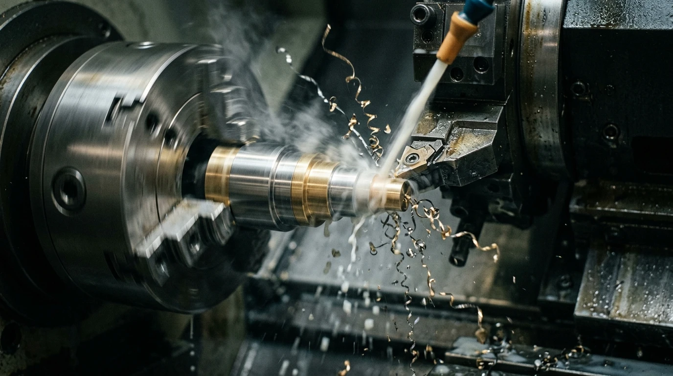
The emergence of AI 3D model generators is fundamentally transforming early-stage industrial design, conceptual styling, and rapid prototyping workflows. Hardware engineers, product designers, and automotive stylists can now generate complex volumetric geometry from text prompts, 2D sketches, and multi-view concept artwork in seconds. However, raw generative models output discrete, non-manifold polygonal surface meshes rather than manufacturing-ready parametric solids. Bridging the gap between an AI-synthesized polygonal mesh and a functional, physical engineering prototype requires a rigorous understanding of digital mesh healing, NURBS reverse engineering, additive layer physics, and precision subtractive CNC machining.
- Core Focus & DFM Scope: Actionable shop-floor engineering guidelines for AI 3D Model Generators, covering material selection, geometric tolerancing, and defect prevention.
- Achievable Tolerance Envelope: General features hold ISO 2768-mK; critical bearing bores, dowel pins, and mating datums hold ±0.010 to ±0.020 mm (±0.0004″ to ±0.0008″), with Wire EDM/grinding to ±0.005 mm (±0.0002″).
- Machining & Surface Integrity: High-speed 3-axis and 4-axis VMCs (with simultaneous 5-axis for complex contours) delivering as-machined Ra 0.8 µm (32 µin) to Ra 0.4 µm (16 µin) per ASME B46.1.
- Metrology & Process Control: On-machine spindle probing paired with 20°C (68°F) climate-controlled Zeiss CMM coordinate verification and calibrated Go/No-Go plug/ring gauges.
- Ex-Factory Turnaround: 4 to 8 business days for as-machined rapid prototypes; 7 to 12 business days for anodized, plated, or multi-operation production runs (excluding 3–5 days air transit).
Executive Summary & Engineering Takeaways (BLUF)
- Generative Mesh vs. Parametric B-Rep: AI 3D model generators output unstructured polygon meshes (OBJ, GLB, STL) with discrete triangular/quad facets, non-manifold edges, and zero thickness. Physical manufacturing requires watertight Boundary Representation (B-Rep) solid models with analytic geometry and ASME Y14.5 datums.
- Digital Remediation Protocol: Prior to fabrication, generative meshes must undergo half-edge topological healing, inverted normal correction, curvature-preserving Quadric Error Metric (QEM) decimation, and volumetric Signed Distance Field (SDF) voxelization to eliminate micro-voids and self-intersections.
- Reverse Engineering Workflows: Organic aesthetic forms are converted into watertight STEP solids via automated NURBS patch-fitting (chordal deviation ≤ 0.020 mm). Critical mechanical enclosures are rebuilt via hybrid parametric reconstruction, introducing uniform 1.5~3.0 mm walls, internal ribs, and brass heat-set insert bosses.
- Additive Manufacturing Deployment: Watertight STLs directly feed industrial 3D printing. Stereolithography (SLA) resin delivers cosmetic hand-feel (0.025~0.050 mm layers); Selective Laser Sintering (SLS) PA12 nylon provides near-isotropic functional durability; Direct Metal Laser Sintering (DMLS) produces topology-optimized titanium and aluminum flight hardware.
- Subtractive CNC Integration: High-speed 3-axis and 4-axis vertical machining centers (VMCs) handle 75%~85%+ of shop-floor enclosure and bracket manufacturing. Simultaneous 5-axis machining is strategically utilized for continuous organic undercuts and complex sculpting. General tolerances adhere to ISO 2768-mK, with critical bearing bores machined to ±0.010~±0.020 mm.
- Dual Metrology Verification: Non-Contact 2.5D Optical Vision Metrology creates full-field CAD deviation color heatmaps (±0.025 mm band) for freeform organic profiles, while contact Zeiss CMM touch probes inspect geometric dimensioning and tolerancing (GD&T) datums.
Engineering Table of Contents
- 1. The AI-to-Hardware Paradigm: Generative Polygonal Meshes vs. Parametric B-Rep CAD
- 2. Comprehensive Benchmark of Leading AI 3D Generative Platforms
- 3. Digital Mesh Remediation & Topological Healing Pipeline
- 4. Reverse Engineering: Converting Polygonal Meshes to Watertight NURBS / STEP Solids
- 5. Additive Manufacturing Validation: SLA, SLS, and DMLS Prototyping
- 6. Precision Subtractive Machining: 3/4-Axis VMC & Strategic 5-Axis CNC Integration
- 7. Quality Inspection, Optical Metrology & ASME Y14.5 Verification
- 8. Frequently Asked Questions (FAQ)
1. The AI-to-Hardware Paradigm: Generative Polygonal Meshes vs. Parametric B-Rep CAD
Modern AI 3D model generators rely on foundational breakthroughs in computer vision, deep learning, and volumetric generative modeling. Most contemporary generative architectures synthesize 3D geometry through one of two primary pathways: multi-view 2D diffusion coupled with Large Reconstruction Models (LRMs), or direct volumetric diffusion in 3D representation spaces such as triplanes, Signed Distance Fields (SDFs), and 3D Gaussian Splatting (3DGS). These models evaluate spatial probabilities to synthesize high-frequency surface detail from textual prompts or single reference images.
However, extracting an explicit 3D surface from implicit neural fields requires algorithms such as Marching Cubes, Dual Contouring, or marching tetrahedra. During this iso-surface discretization, continuous mathematical fields are sampled onto discrete voxel grids. The resulting output is invariably a polygonal surface mesh—typically packaged in OBJ, GLB, or STL formats. While visually compelling in a digital rendering viewport, these meshes possess fundamental mathematical characteristics that conflict directly with manufacturing reality:
- Discrete Faceted Boundaries vs. Continuous Analytic Solids: A polygon mesh approximates curved topology using thousands or millions of planar triangular facets. In contrast, mechanical CAD systems (such as SolidWorks, Siemens NX, and Autodesk Inventor) represent geometry as Boundary Representation (B-Rep) solids based on exact analytic surfaces (planes, cylinders, cones, tori) and Non-Uniform Rational B-Splines (NURBS). A cylindrical bore in an AI mesh is merely a faceted polygon tube lacking an exact centerline axis, cylindrical radius, or circular cross-section.
- Absence of Material Volume and Wall Thickness: AI-generated meshes are infinitely thin, hollow surface shells (2D topological manifolds embedded in 3D Euclidean space). They possess no defined wall thickness, interior structural ribbing, or solid core volume. Slicing such geometry for additive manufacturing or attempting toolpath generation for subtractive milling without manual thickening creates empty air toolpaths or severe machine crashes.
- Topological Defects: Iso-surface extraction algorithms frequently produce non-manifold geometry, including edges shared by more than two polygons (T-junctions), zero-volume self-intersections, disjunct internal floating shells, and inverted surface normal vectors where outward faces point inward toward the object cavity.
- Lack of Parametric Associativity and Tolerancing: In mechanical production, geometric dimensions are tied to manufacturing tolerances, draft angles, and reference datums defined by standards like ASME Y14.5. A raw AI mesh lacks parametric feature history, preventing engineers from modifying an internal hole diameter, updating an O-ring gland width, or specifying an ISO 2768-mK fit.
Because of this fundamental divergence, hardware development teams cannot treat generative AI meshes as production-ready geometry. Instead, engineering teams treat the AI 3D output as a high-density “digital clay” scaffold—a volumetric concept that must pass through rigorous digital remediation and reverse engineering before touching machine tool cutting edges or industrial additive lasers.
2. Comprehensive Benchmark of Leading AI 3D Generative Platforms
The landscape of AI 3D model generators has expanded rapidly, offering distinct architectural trade-offs between generation speed, geometric coherence, topology density, and physical manufacturing translation feasibility. Evaluating these platforms from a manufacturing engineering perspective requires looking beyond aesthetic visual rendering to examine underlying polygon structures, surface continuity, and topological manifoldness.
Meshy AI: Meshy operates on a hybrid architecture combining multi-view text/image diffusion with automated remeshing algorithms. It excels at generating structured quad-dominant or balanced triangle meshes from single-view industrial design sketches. In addition, Meshy automatically computes UV unwrap coordinates and generates comprehensive Physically Based Rendering (PBR) texture maps (Albedo, Roughness, Metallic, Normal). From an engineering standpoint, Meshy provides clean overall silhouette definition, but its native outputs still exhibit rounded edge radii on intended sharp mechanical corners and require manual feature re-sharpening.
Tripo AI: Powered by a large feed-forward 3D transformer model, Tripo emphasizes ultra-rapid generation speeds, delivering draft 3D meshes within 10 to 15 seconds. It provides native mesh repair toggles and basic quad-topology decimation. While outstanding for rapid mechanical package envelope ideation and ergonomic styling reviews, Tripo models often incorporate micro-scale surface waviness (stochastic noise from neural field extraction) that must be smoothed via laplacian filtering before precision reverse engineering.
Rodin (Hyper3D / Deemos): Rodin employs Diffusion Transformers (DiT) specifically optimized for high-fidelity 3D assets and intricate organic surfaces. It synthesizes exceptionally rich geometric detail with multi-layered contour resolution. However, Rodin outputs dense, high-polygon triangle meshes (frequently exceeding 500,000 to 1,000,000 facets). Importing such heavy meshes directly into standard parametric CAD software triggers memory exhaustion and severe graphics lag, necessitating aggressive, curvature-adaptive decimation.
Luma AI (Genie & NeRF-Based Pipeline): Originating from neural radiance field and Gaussian splatting reconstruction, Luma AI provides robust text-to-3D and video-to-3D capabilities. It reconstructs complex organic silhouettes with high spatial realism. Nonetheless, because its architecture leans heavily toward photographic volumetric capture, sharp industrial features (such as 90° perpendicular mounting faces, knife edges, and precision counterbores) tend to blur into chamfered, organic approximations that require complete CAD surface reconstruction.
Spline AI & Latent Point Cloud Synthesizers: Spline AI combines generative prompts with web-based procedural modeling nodes. While better suited for consumer packaging and clean UI geometry, its generative components operate alongside latent point cloud synthesizers (such as Point-E and Shap-E). Point cloud outputs represent discrete 3D spatial coordinates without explicit surface connectivity; they require secondary Poisson surface reconstruction or alpha-shape meshing to generate closed surface skins.
| Platform | Core Generative Engine | Input Modality | Mesh Format & Topology | Texture / PBR Baking | Primary DFM Translation Bottleneck |
|---|---|---|---|---|---|
| Meshy AI | Multi-View Diffusion + Voxel Remeshing | Text prompt, 2D sketch, concept image | OBJ, GLB, USDZ; structured quads/triangles | Full PBR (Albedo, Normal, Roughness, Metal) | Corner fillet rounding; requires edge sharpening for mechanical interfaces |
| Tripo AI | Large Feed-Forward 3D Transformer | Text description, single image, multi-view | GLB, OBJ, STL; adaptive triangle density | Basic diffuse vertex color / UV albedo | Neural sampling ripple noise; requires surface smoothing and feature isolation |
| Rodin (Hyper3D) | Diffusion Transformer (DiT) Architecture | Text prompt, high-res 2D image | OBJ, FBX, GLB; ultra-dense triangles (>500k) | High-resolution 4K/8K texture mapping | Heavy polygon overhead; mandates QEM decimation before CAD patch fitting |
| Luma AI Genie | Neural Radiance Field (NeRF) Synthesis | Text prompt, 360° video scan | OBJ, GLTF, USDZ; irregular surface mesh | View-dependent radiance mapped to diffuse | Non-planar flat regions; absence of true geometric datum planes |
| Spline AI / Point-E | Procedural Nodes / Latent Point Diffusion | Text commands, geometric parametric inputs | GLTF, STL, Point Cloud XYZ | Procedural shaders / basic color channels | Limited to simple primitives; point clouds require surface reconstruction |
3. Digital Mesh Remediation & Topological Healing Pipeline
Directly exporting an AI-generated 3D model into CAM toolpath generators or additive manufacturing slicers inevitably causes severe algorithmic errors. Slicing software relies on closed, continuous 2D boundary polygons generated by slicing a closed 3D volume at specific Z-height intervals. When a slicer encounters non-manifold geometry, self-intersecting facets, or inverted normal vectors, it generates zero-thickness toolpaths, infill voids, or unresolvable internal infill islands.
To prepare an AI-generated polygon mesh for production, our in-house engineering team executes a systematic four-stage computational mesh remediation pipeline utilizing industrial tools such as Blender, MeshMixer, and Geomagic Design X:
- Stage 1: Non-Manifold Geometry Elimination: A 2-manifold surface is mathematically defined as a surface where every point has a neighborhood homeomorphic to an open disk in 2D Euclidean space. In practical mesh terms, every edge must connect exactly two triangular faces, and every vertex must be surrounded by a single continuous ring of triangles. Mesh repair algorithms scan the half-edge data structure to identify non-manifold “T-junction” edges (where three or more faces converge) and “bow-tie” vertices (where two distinct cones of triangles meet at a single pinch point). The algorithm slices these junctions, duplicates the boundary vertices, and isolates clean, separable surface shells.
- Stage 2: Normal Vector Orientation and Inversion Rectification: Surface normal vectors define which side of a polygonal facet represents solid material and which side represents ambient space. Multi-view neural networks frequently output patches of inverted normals, causing CAM toolpaths to treat external convex surfaces as internal voids. A breadth-first search (BFS) across connected half-edges re-indexes vertex winding orders (counter-clockwise orientation) to guarantee consistent outward-pointing normals across the entire shell. Concurrently, internal hidden geometry—such as stray interior triangles created during marching cubes extraction—is purged.
- Stage 3: Curvature-Preserving Decimation & Isotropic Remeshing: Generative AI meshes often suffer from severe triangle aspect ratio skew, where narrow “sliver” triangles exhibit length-to-width aspect ratios exceeding 10:1. These slivers cause finite element analysis (FEA) singularities and CAM interpolation stutter. By applying Garland-Heckbert Quadric Error Metric (QEM) decimation, the mesh polygon count is reduced by 60%~85% without sacrificing critical boundary sharpness. Subsequent isotropic remeshing equalizes triangle edge lengths across continuous organic surfaces, establishing an equilateral facet distribution.
- Stage 4: Volumetric VDB / Signed Distance Field (SDF) Voxelization: For models exhibiting microscopic pinholes, overlapping boundary shells, or self-intersecting organic tentacles, explicit polygonal healing can fail. In such scenarios, the mesh is converted into a volumetric narrow-band Signed Distance Field (OpenVDB grid). Morphological closing operations (dilation by 0.1~0.2 mm followed by equivalent erosion) fuse micro-gaps and dissolve internal geometric singularities. A secondary Dual Contouring extraction then outputs a watertight 2-manifold solid shell.
The successful execution of this digital mesh remediation protocol establishes an error-free geometric foundation. Once the polygonal wireframe is topologically healed, watertight, and curvature-optimized, engineers can proceed with high-fidelity reverse engineering into parametric CAD solids and multi-process physical prototyping across additive and subtractive manufacturing pathways.
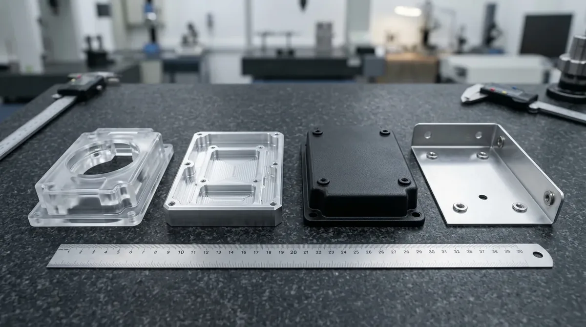
4. Reverse Engineering: Converting Polygonal Meshes to Watertight NURBS / STEP Solids
While an optimized, watertight STL mesh can directly drive additive manufacturing, it remains fundamentally uneditable in mechanical engineering CAD environments. Subtractive CNC machining, injection mold tooling, and precision assembly integration mandate standard neutral solid exchange formats—specifically STEP (ISO 10303 AP203/AP214) or IGES. Transforming an organic polygonal mesh into a solid STEP B-Rep entity is accomplished through two distinct reverse engineering methodologies:
Methodology A: Algorithmic Auto-Surfacing (NURBS Patch-Fitting): For complex organic sculptures, prosthetic sockets, or consumer aesthetic styling surfaces where preserving freeform contour curvature is critical, automated NURBS surface fitting provides the fastest path to solid CAD. Using platforms like Geomagic Design X, Rhino (via Resurf/VSR), or Siemens NX:
- The healed polygon mesh is segmented into topological regions based on principal Gaussian curvature and mean curvature tensors.
- A four-sided patch curve network is projected across the mesh, establishing boundary curves between adjacent regions.
- Bi-cubic Non-Uniform Rational B-Spline (NURBS) surface patches are mathematically fitted to the underlying facets, enforcing C1 (tangent) and C2 (curvature) continuity across patch boundaries to prevent visual seam creases.
- Chordal deviation analysis evaluates the maximum orthogonal distance between the fitted NURBS surface and the source polygon vertices, maintaining a tight deviation band of ≤ 0.020 mm across functional surfaces.
- The software sews the interconnected surface patches into a closed volumetric quilt and converts the quilt into a solid B-Rep body ready for STEP export.
Methodology B: Hybrid Parametric Reconstruction: When the AI model represents a mechanical housing, electronic enclosure, or structural bracket, auto-surfacing is insufficient. Auto-surfacing merely turns faceted organic blobs into smooth organic blobs without providing functional planar mating faces, uniform wall thicknesses, or precision fastener locations. Hybrid parametric reconstruction bridges this gap by utilizing the AI mesh as an immutable reference “digital clay” scaffold:
- Datum Alignment: The mesh is oriented within the CAD coordinate system by identifying primary functional baselines. Datum Plane A is aligned to the intended base surface, Datum Axis B to a central rotational axis, and Datum Plane C to an alignment slot or symmetric center plane in accordance with ASME Y14.5.
- Cross-Sectional Slicing: Reference planes are intersected through the mesh at strategic stations (e.g., every 5.0 mm or at critical transition boundaries), generating 2D cross-sectional polyline slices.
- Parametric Sketch Extraction: Parametric sketch geometry—tangent arcs, concentric circles, linear extrusion walls, and draft angles—is fitted over the sliced polylines.
- Wall Thickness Uniformity: The solid shell feature creates a constant nominal wall thickness (typically 1.5 to 3.0 mm for injection molded plastics or functional SLA/SLS enclosures), preventing sink marks, internal thermal stresses, and non-uniform cooling warpage.
- Mechanical Hardware Integration: Engineers incorporate functional internal features, including structural stiffening gussets, snap-fit cantilever joints, O-ring sealing grooves, and screw bosses designed with counterbores to receive ultrasonic or thermal brass heat-set threaded inserts (such as M2.5, M3, or M4 inserts).
| Engineering Phase | Primary Software Tool | Core Algorithmic Operation | Target Geometric Benchmark | Deliverable Format |
|---|---|---|---|---|
| 1. Mesh Remediation | Blender / MeshMixer / MeshLab | Non-manifold repair, QEM decimation, VDB voxel fusion | 2-manifold, self-intersections removed | Watertight binary STL |
| 2. Region Segmentation | Geomagic Design X / Rhino | Gaussian/Mean curvature tensor classification | Clean planar, cylindrical, and freeform boundary zones | Segmented mesh quilt |
| 3. Auto-Surfacing | Geomagic Design X / FreeCAD | Bi-cubic B-spline patch fitting with C1/C2 continuity | Chordal deviation ≤ 0.020 mm | Watertight NURBS solid body |
| 4. Hybrid Parametric CAD | SolidWorks / Siemens NX | Cross-section slicing, analytic feature lofting, shelling | Uniform 1.5~3.0 mm walls, ASME Y14.5 datums | Parametric native CAD |
| 5. Manufacturing Release | Mastercam / PowerMill / Slicers | Toolpath generation, support generation, DFM review | ISO 2768-mK shop general tolerance | STEP AP214 / G-code / CLI |
5. Additive Manufacturing Validation: SLA, SLS, and DMLS Prototyping
Physical rapid prototyping bridges the crucial transition from virtual AI-generated concepts to tangible hardware validation. Additive manufacturing (3D printing) is uniquely suited for fabricating generative geometries because industrial 3D printers construct parts layer by layer, circumventing many traditional tool access and draft angle constraints. Depending on whether the prototype is intended for aesthetic styling review, functional snap-fit testing, or high-stress structural validation, distinct additive manufacturing processes are deployed:
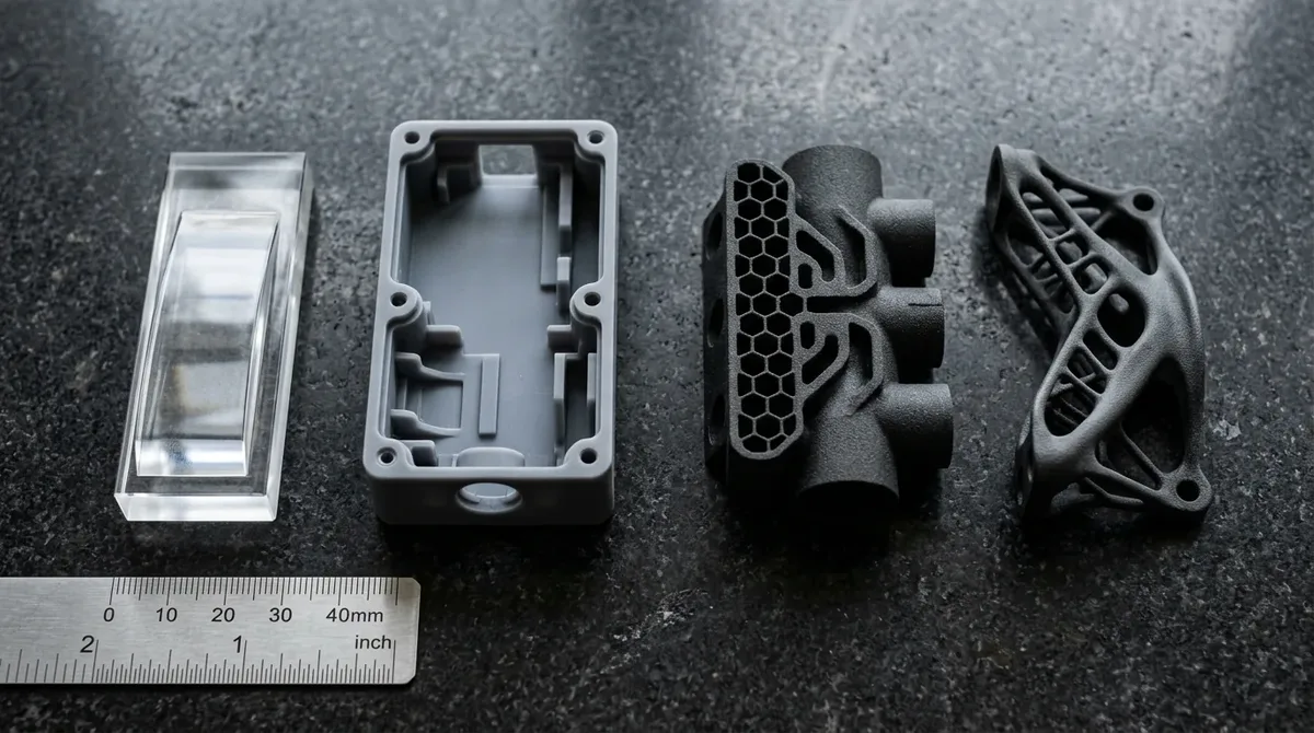
Stereolithography (SLA): SLA utilizes an ultraviolet (UV) laser (typically 355 nm or 405 nm) to selectively photopolymerize liquid photosensitive epoxy or acrylate resin layer by layer. Operating with layer resolutions between 0.025 mm and 0.050 mm, SLA delivers superior surface smoothness (as-printed Ra approximately 1.2 to 2.5 µm) and crisp feature resolution. It is the premier choice for ergonomic styling mockups, handheld consumer electronics housings, and transparent optical fluid enclosures. Following printing, parts undergo solvent wash (isopropanol) to remove uncured resin and controlled thermal/UV chamber post-curing to maximize polymer cross-linking density.
Selective Laser Sintering (SLS): SLS employs a high-power CO2 or fiber laser to sinter micronized engineering thermoplastic powder—primarily Polyamide 12 (Nylon PA12) or glass-bead reinforced PA12-GF—in a heated build chamber. A fundamental engineering advantage of SLS is that the surrounding unsintered powder bed acts as continuous self-supporting media during the build. This completely eliminates the need for sacrificial support structures, allowing AI-generated internal fluid channels, multi-chamber manifolds, and intricate organic lattices to be printed without support removal scarring. SLS PA12 components exhibit near-isotropic mechanical properties, achieving tensile strengths of 45 to 48 MPa and heat deflection temperatures (HDT) up to 163°C at 0.45 MPa, making them ideal for functional under-hood ducting, drone airframes, and snap-fit electronics enclosures.
Direct Metal Laser Sintering (DMLS / SLM): For aerospace, medical, and high-performance automotive applications, generative topology-optimized models must be produced in engineering metals. DMLS uses a precision fiber laser to completely melt fine metallic powders—such as Ti-6Al-4V Grade 5, AlSi10Mg aluminum, and 316L stainless steel—in an inert argon gas atmosphere. DMLS enables lightweight hollow internal structures that cannot be machined via traditional tooling. However, metal additive manufacturing requires careful thermal residual stress management: components must undergo vacuum furnace stress-relief annealing prior to electrical discharge wire cutting (wire EDM) from the build substrate plate to prevent severe stress-induced warping.
Our in-house additive manufacturing lab couples advanced multi-technology 3D printing with rigorous optical metrology inspection. By validating layer adhesion, volumetric density, and dimensional accuracy across SLA, SLS, and DMLS platforms, product development teams verify the physical feasibility of AI concepts within days, evaluating optical clarity, snap-fit mechanics, and generative structural lattices side by side.
| Process | Material Palette | Layer Thickness | Surface Finish (Ra) | Mechanical Rigidity | Ideal Prototyping Stage |
|---|---|---|---|---|---|
| Stereolithography (SLA) | Standard/Tough/Clear Photopolymer Resin | 0.025 ~ 0.050 mm | 1.2 ~ 2.5 µm (smooth) | Moderate; brittle if over-cured | Ergonomic styling, cosmetic mockups, proof-of-concept |
| Selective Laser Sintering (SLS) | PA12 (Nylon), PA11, PA12-GF Glass-Filled | 0.080 ~ 0.120 mm | 4.0 ~ 8.0 µm (grainy/matte) | High impact strength, isotropic | Functional testing, snap-fit assemblies, complex ducting |
| Direct Metal Laser Sintering (DMLS) | Ti-6Al-4V, AlSi10Mg, 316L Stainless Steel | 0.030 ~ 0.060 mm | 6.0 ~ 12.0 µm (as-sintered) | Ultra-high structural yield strength | Structural load-bearing components, thermal heat exchangers |
| PolyJet Multi-Material | Digital ABS, Tango elastomeric resins | 0.018 ~ 0.030 mm | 1.0 ~ 2.0 µm (high gloss) | Variable Shore A to Shore D | Overmolding mockups, dual-hardness seals, medical models |
6. Precision Subtractive Machining: 3/4-Axis VMC & Strategic 5-Axis CNC Integration
While additive manufacturing excels at complex organic forms, subtractive CNC machining remains the gold standard when prototypes require true engineering production materials (such as solid billet 6061-T6 aluminum, 304/316L stainless steel, PEEK, or Delrin/POM), proven isotropic mechanical properties, and precision dimensional tolerances. Transitioning an AI-derived solid CAD model into a CNC machining center requires addressing fundamental CAM toolpath kinematics and fixture workholding physics.
Shop-Floor Workhorse Reality: 3-Axis & 4-Axis VMC Dominance: In modern machine shops, high-speed 3-axis and 4-axis vertical machining centers (VMCs)—such as Brother high-speed tapping centers, Fanuc Robodrill, and Haas/Mazak vertical mills—represent 75% to 85%+ of overall machining capacity. Enclosures, mounting plates, sensor brackets, and chassis components derived from AI designs are machined most cost-effectively and rapidly on 3-axis VMC setups utilizing precision Kurt vises, modular zero-point clamping plates, or custom aluminum soft jaws. A 4th-axis rotary indexer allows multi-sided machining around a central axis in a single clamping setup, maintaining tight datum relationships across perpendicular faces.
Strategic Deployment of Simultaneous 5-Axis Machining: Full simultaneous 5-axis machining centers (such as trunnion A/C tilting tables or swivel-head B/C configurations) carry significantly higher hourly machine rates (typically 2 to 4 times the rate of a standard 3-axis mill) and demand complex CAM collision avoidance simulation. Therefore, 5-axis CNC machining is deployed strategically: it is reserved for parts with continuous multi-directional undercuts, complex organic aerodynamic impellers/blisks, deep sculpted mold cavities, and topological aerospace hardware where rigid tool access cannot be achieved via 3-axis or 4-axis positioning. For conventional housings, mislabeling a 3-axis part as “5-axis machined” represents an unneeded operational expense.
CAM Toolpath Challenges: Scallop Height & Ball-Nose Apex Dead Zones: Milling organic AI-derived freeform surfaces presents unique cutting mechanics challenges:
- Cusp and Scallop Height Mechanics: When finishing organic 3D contours with a spherical ball-nose end mill, adjacent tool passes leave microscopic material ridges known as cusps or scallops. The theoretical scallop height h is calculated as:
h ≈ b² / (8 · R)
where b is the cross-feed stepover distance and R is the effective cutter corner radius. To achieve an optical or SPI-spec finish (Ra ≤ 0.4 µm) with a traditional ball-nose tool, stepovers must be restricted to tiny increments (0.05 to 0.15 mm), leading to prolonged machining cycle times. - Overcoming the Apex Dead Zone: At the very center tip of a rotating ball-nose tool, the effective cutting diameter approaches zero (deff → 0). According to the linear cutting speed formula
vc = π · deff · n / 1000, the linear cutting speed at the apex drops to 0 m/min. When a 3-axis mill traverses flat or gently sloping surfaces with the tool tip perpendicular to the stock, the tool does not shear metal—it plows, rubs, and burnishes the workpiece, causing localized work-hardening, galling, and premature tool chipping. On 5-axis CNC centers, CAM programmers eliminate this issue by tilting the tool axis at a 15° to 25° lead/lag angle, engaging the sharp peripheral cutting flutes at optimal cutting velocity. - Circle-Segment (Barrel) Tooling Innovation: Modern CAM strategies for organic AI geometry increasingly utilize circle-segment (barrel and lens) cutters. Featuring large effective profile radii (Reff = 150 to 500 mm) on a compact shank, barrel cutters achieve equivalent or superior scallop heights with stepovers 4 to 8 times wider than conventional ball-nose tools, cutting finishing cycle times by 60% to 75%.
Realistic Tolerancing Standards: In accordance with industrial manufacturing standards, general non-critical tolerances for precision CNC milling adhere to ISO 2768-mK. Critical mechanical mating features—such as bearing bores, linear dowel pin holes, and precision ground slideways—are directly dimensioned on technical drawings with specific numerical tolerances of ±0.010 mm to ±0.020 mm. Ultra-precision features requiring ±0.005 mm tolerances are achieved through specialized slow-wire electrical discharge machining (wire EDM) or precision cylindrical/surface grinding. Claims of micro-inch or sub-0.005 mm tolerances across general milled parts are physically unrealistic in production environments due to thermal expansion gradients and machine tool elasticity.
| Geometric Feature | Additive Prototyping Constraint | Subtractive CNC Milling Constraint | Critical Metrology Benchmark |
|---|---|---|---|
| Internal Cavities & Pockets | SLS/DMLS require escape holes (≥ 3.0 mm) for powder evacuation | Depth-to-width ratio ≤ 4:1 to prevent tool deflection; corner radius R ≥ 1.15 × cutter R | CMM touch probe internal corner profile |
| Thin Wall Sections | Minimum 0.8 mm (SLA) to 1.2 mm (SLS) to prevent curling | Minimum 1.0 mm (aluminum) to 1.5 mm (plastics) to avoid chatter vibration | Ultrasonic thickness gauge / optical scan |
| Threaded Connections | Direct printed threads brittle; use ultrasonic brass heat-set inserts | CNC single-point thread milling or rigid tapping (6H/6g thread class) | Standard Go/No-Go thread plug gauges |
| Organic Undercuts | Self-supporting up to 45°; SLS handles undercuts without supports | Requires lollipop cutters, T-slot tools, or simultaneous 5-axis re-orientation | Zeiss CMM multi-point contour deviation report |
| Precision Bores & Datums | Print undersized; ream or secondary machine post-print | Precision boring head or circular helical interpolation (±0.010 mm) | Zeiss CMM true position ∅0.015 mm MMC |
7. Quality Inspection, Optical Metrology & ASME Y14.5 Verification
Verifying the physical accuracy of an AI-derived prototype requires a hybrid inspection methodology. Traditional coordinate measuring machines (CMMs) excel at probing discrete prismatic geometries—such as planes, cylinders, and bolt circle diameters—but are ill-suited for mapping continuous, non-analytic freeform organic contours. Conversely, purely visual inspection cannot verify precision mechanical tolerance fits.
To provide complete dimensional confidence, our inspection laboratory deploys a dual-track metrology verification framework:
- Non-Contact 2.5D Optical Vision Metrology: Non-contact 2.5D optical vision measuring systems (capturing up to millions of discrete surface coordinate points per scan with spatial volumetric accuracy of ±0.015 mm) digitize the entire physical prototype. The resulting point cloud is aligned to the nominal reverse-engineered STEP CAD solid using a Best-Fit Gaussian alignment algorithm. Metrology software generates a full-field 3D color deviation heatmap:
• Green Band (±0.025 mm): Indicates geometry conforming exactly within design tolerance.
• Red / Yellow Band: Indicates positive excess material, pointing to thermal warp expansion in additive prints or tool deflection in CNC milling.
• Blue Band: Indicates negative material undercut or over-cutting. - Zeiss Contact CMM Touch Probing: For all primary assembly interfaces, locating dowel pin holes, and sealing lands, contact touch-trigger ruby probes on a calibrated Zeiss CMM inspect geometric dimensioning and tolerancing (GD&T) features per ASME Y14.5-2018. The machine verifies Datum A flatness (≤ 0.010 mm), bore perpendicularity, and true position (∅0.015 mm maximum material condition).
- Surface Roughness Profilometry: Calibrated diamond-stylus contact profilometers measure surface micro-roughness (Ra, Rz) per ISO 4287 / ASME B46.1 across both as-printed additive surfaces and CNC-machined faces, verifying that cosmetic and sealing specifications are met.
Every functional prototype shipped from our facility is accompanied by full traceability documentation, including raw material mill test reports (MTR), heat treatment inspection records, and comprehensive dimensional inspection reports. This ensures complete engineering integrity as teams scale from generative concept mockups to production-grade hardware.
8. Frequently Asked Questions (FAQ)
You can directly 3D print an AI-generated mesh only if it is completely watertight (2-manifold) with positive uniform wall thickness. Most raw generative outputs contain non-manifold edges, self-intersecting polygons, zero-thickness shells, and inverted normals. Slicing software requires these defects to be repaired via half-edge topological healing or volumetric SDF voxelization before generating toolpaths.
Engineers use two primary reverse engineering workflows: automated NURBS patch-fitting (fitting networks of B-spline surfaces over organic contours with chordal deviations ≤ 0.020 mm for STEP export), and hybrid parametric reconstruction (using the AI mesh as a reference scaffold, slicing 2D cross-sections, and rebuilding parametric solid features with uniform wall thicknesses, screw bosses, and ASME Y14.5 datums).
Industrial 3D printing is ideal for rapid visual evaluation, complex organic ducting, and lightweight lattices. However, CNC machining is required when prototypes demand authentic isotropic engineering metals (such as 6061-T6 aluminum or 316L stainless steel), production plastics (PEEK, Delrin), tight geometric tolerances (±0.010 mm to ±0.020 mm), and superior surface finishes (Ra ≤ 0.4 µm) that additive processes cannot directly achieve.
Machining organic contours requires spherical ball-nose or advanced circle-segment (barrel) end mills. CAM programmers optimize cross-feed stepovers to control scallop ridge height (h ≈ b² / 8R). Furthermore, on 5-axis machining centers, the tool axis is tilted 15° to 25° to eliminate the ball-nose apex dead zone (where cutting speed drops to 0 m/min), preventing metal burnishing and achieving mirror-smooth surface finishes.
For rapid prototyping and DFM review, engineering teams submit 3D CAD files in neutral formats such as STEP (.stp), IGES (.igs), or watertight STL (.stl). Our in-house engineering team provides comprehensive DFM feedback and quotation within 24 hours, with rapid prototypes manufactured and inspected in as little as 4 to 8 business days.
Ready to Turn Your AI 3D Concepts into Precision Hardware?
Have an AI-generated concept mesh, polygonal model, or parametric CAD assembly ready for physical prototyping? AS Prototypes offers comprehensive digital mesh verification, industrial additive manufacturing (3D printing services including SLA, SLS, and DMLS), and tight-tolerance multi-axis subtractive precision CNC machining services down to ±0.010 mm.
Our senior engineering team provides comprehensive Design for Manufacturing (DFM) reviews within 24 hours, helping you transition seamlessly from generative digital geometry to production-grade physical prototypes in as little as 4 to 8 business days.
Upload 3D Models (STEP/STL/IGES) for Instant Engineering RFQ →







