

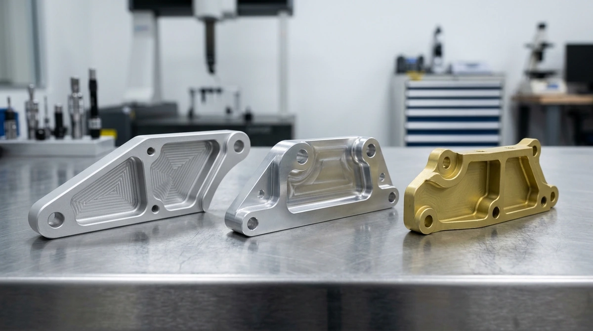
Quick Engineering Takeaways (BLUF)
- The General Workhorse: Aluminum 6061-T651 remains the industry standard for precision enclosures, mounting brackets, and robotics chassis, delivering a balanced 80% machinability rating, excellent anodizing receptivity, and superior cost-efficiency.
- The High-Stress Benchmark: Aluminum 7075-T651 offers extreme yield strength (≥ 503 MPa) rivaling structural steels, making it mandatory for aerospace airframes, defense brackets, and high-load racing uprights; specify T7351 temper when stress-corrosion cracking (SCC) mitigation is critical.
- Fatigue & Fracture Toughness: Aluminum 2024-T351 excels in cyclic loading and aerospace tension skins with high fracture toughness (KIC ≈ 34 MPa·m1/2), though its high copper content demands surface protection against galvanic corrosion.
- Distortion Control: Always specify stretched, stress-relieved tempers (T651 or T7351) over standard T6 to eliminate residual rolling stresses and prevent asymmetrical part bowing during aggressive roughing.
- Anodizing Dimensional Impact: MIL-A-8625 Type II film is 8–25 μm thick and adds 4–12 μm per surface (50% penetration / 50% buildup), while 40–50 μm Type III Hardcoat adds 20–25 μm per surface, requiring pre-machining dimensional compensation or precision thread masking.
Aluminum alloys represent the engineering foundation of modern precision manufacturing across aerospace, defense, telecommunications, robotics, and medical instrumentation. Their exceptional strength-to-weight ratio, high thermal conductivity (130–220 W/m·K), excellent electrical conductivity, and rapid chip formation characteristics make them the most widely specified metal category in CNC machine shops worldwide. However, selecting the incorrect alloy grade or improper heat-treatment temper can trigger catastrophic production issues, including severe machining-induced part distortion, built-up edge (BUE), poor surface roughness, or rapid fatigue failure under cyclic service loads.
Achieving micron-level dimensional fidelity on CNC machined aluminum components requires an integrated understanding of metallurgy, cutting tool dynamics, cutting fluid chemistry, and post-machining surface finishing. This guide examines the metallurgical classifications, mechanical property trade-offs, high-speed cutting parameters, Design for Manufacturing (DFM) guidelines, and quality assurance protocols necessary to optimize aluminum alloy selection for custom precision CNC machining.
1. Metallurgy & Classification: Wrought vs. Cast Aluminum Alloys
Aluminum alloys are metallurgically categorized into two primary divisions: wrought alloys and cast alloys. Wrought aluminum alloys undergo mechanical working processes—such as hot rolling, cold drawing, extrusion, or open/closed die forging—from cast billets. This mechanical deformation breaks down cast dendritic structures, fragments intermetallic inclusions, refines crystal grain boundaries, and heals micro-porosity. Consequently, wrought alloys consistently deliver superior tensile yield strength, elongation, fracture toughness, and fatigue endurance compared to cast alternatives.
In contrast, cast aluminum alloys (such as A380, A356, and AlSi10Mg) are melted and poured directly into sand molds, investment shells, or high-pressure die casting tooling to produce complex, near-net geometries with intricate internal passages. While casting reduces raw material waste on high-volume production, cast alloys possess inherent shrinkage porosity, micro-voids, and brittle silicon-rich phases that limit dynamic mechanical performance and make achieving optical-grade anodized finishes impossible. Precision CNC machining overwhelmingly utilizes wrought billets and extruded plates to guarantee 100% internal density and predictable structural performance.
The 4-Digit Wrought Alloy Designation System
The Aluminum Association (AA) 4-digit classification system identifies wrought alloys based on their principal alloying elements, which dictate their precipitation hardening mechanisms and physical characteristics:
- 1xxx Series (Pure Aluminum ≥ 99.0%): Non-heat treatable. Highly ductile, exceptional electrical conductivity (≥ 60% IACS) and thermal conductivity (≈ 220 W/m·K), but low mechanical strength (yield ≈ 30–100 MPa). Primarily used for busbars, electrical shielding, and chemical tanks.
- 2xxx Series (Copper 1.9%–6.8%): Heat treatable. Alloying with copper yields high tensile strength and superior fatigue endurance through Al2Cu (θ′) precipitate hardening. Exhibits good machinability but poor weldability and lower atmospheric corrosion resistance, requiring protective anodizing or alclad coatings. Predominant in aerospace tension structures (2024, 2014).
- 3xxx Series (Manganese 1.0%–1.5%): Non-heat treatable. Manganese provides solid-solution strengthening, yielding moderate mechanical strength with high ductility and excellent formability. Highly resistant to general atmospheric and chemical attack (3003, 3105).
- 4xxx Series (Silicon 4.5%–12.0%): Non-heat treatable (mostly). Silicon lowers the melting point and dramatically reduces thermal expansion. Commonly used for welding wire (4043) and specialized wear-resistant forged pistons (4032).
- 5xxx Series (Magnesium 0.8%–5.0%): Non-heat treatable (strain-hardenable). Magnesium provides solid-solution strengthening, superior fatigue resistance, and exceptional marine salt-water corrosion resistance. Highly weldable, but prone to gumminess during CNC milling if chip breakers are inadequate (5052, 5083).
- 6xxx Series (Magnesium & Silicon 0.4%–1.5%): Heat treatable. Forms magnesium silicide (Mg2Si) precipitates during artificial aging. Delivers an optimal balance of machinability, structural strength, weldability, corrosion resistance, and aesthetic anodizing receptivity (6061, 6063, 6082). Represents over 70% of structural CNC milling volume.
- 7xxx Series (Zinc 1.0%–8.0%, Magnesium & Copper): Heat treatable. Precipitation hardening via metastable η′ (MgZn2) phases yields ultra-high tensile yield strength exceeding 500 MPa. Serves as the premier structural metal for critical aerospace airframe members, military hardware, and high-stress performance machinery (7075, 7050, 7068).
Understanding Temper Designations & Stress Relief
Specifying the chemical alloy composition represents only half of the engineering equation; the mechanical temper designation dictates ultimate strength, ductility, and internal residual stress state. The most critical tempers encountered in precision CNC machining include:
- O (Annealed): Fully recrystallized condition exhibiting maximum ductility and lowest yield strength. Specified for extreme cold forming or severe deep-drawing prior to secondary machining.
- H (Strain-Hardened): Applied to non-heat-treatable alloys (3xxx, 5xxx). Sub-divisions such as H32 indicate strain hardening followed by low-temperature thermal stabilization to prevent property drift over time.
- T6 (Solution Heat-Treated & Artificially Aged): Material is soaked at elevated temperature (≈ 530°C for 6061), water quenched to freeze solid solution, and artificially aged (≈ 175°C) to precipitate coherent hardening phases. Delivers peak tensile yield strength.
- T651 (Stress-Relieved by Controlled Stretching): Following solution heat-treatment and quenching, the plate or billet is subjected to a controlled mechanical stretch of 1.5% to 3.0% permanent set prior to artificial aging. This stretching process mechanically relieves severe internal thermal quenching stresses. For precision CNC milling involving aggressive material removal, deep cavities, or thin floor sections, specifying T651 temper is mandatory to prevent severe part warping, twisting, and bowing.
- T7351 (Overaged for Stress-Corrosion Resistance): Subjected to two-stage overaging following controlled stretching. While tensile yield drops by approximately 10% to 15% compared to T651, T7351 eliminates susceptibility to catastrophic intergranular stress-corrosion cracking (SCC) under continuous tensile loads in aggressive environments.
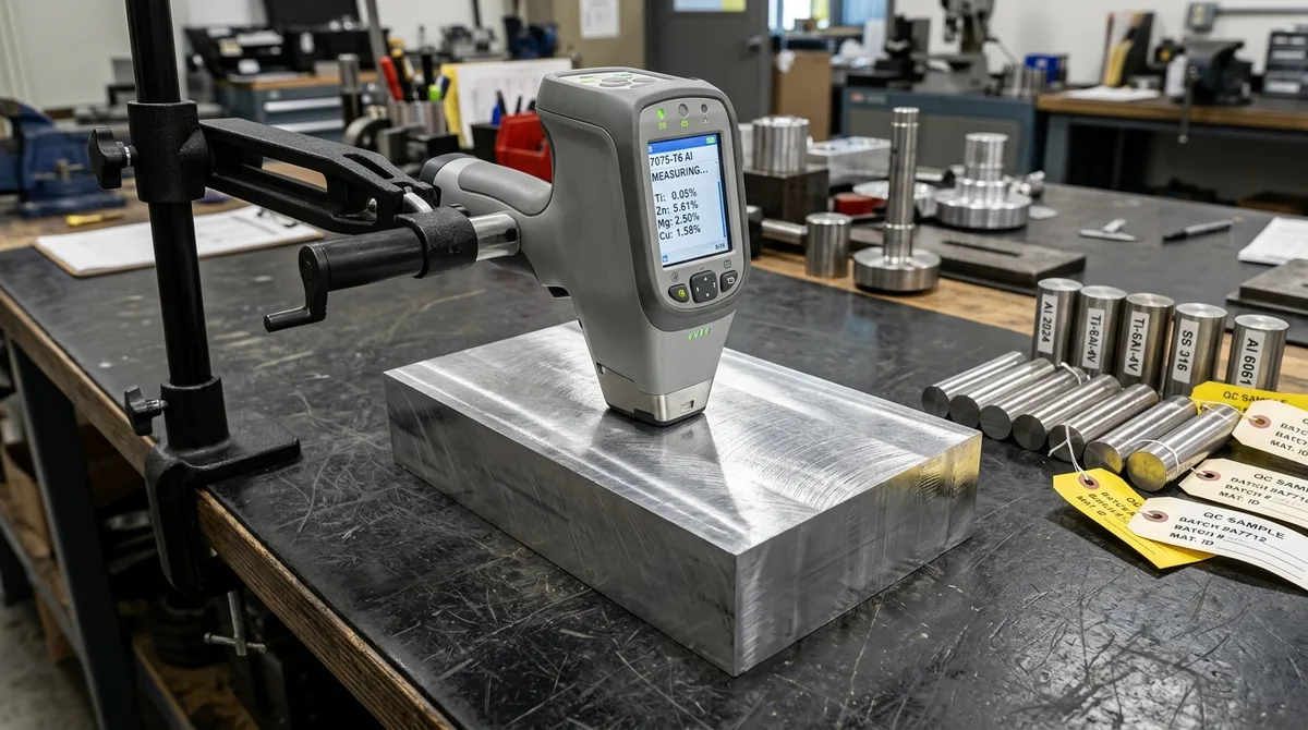
Before raw aluminum stock enters the machine shop, material authenticity must be validated against mill test certifications. Our quality inspection facility utilizes handheld X-ray fluorescence (XRF) spectrometry to perform non-destructive Positive Material Identification (PMI) on incoming raw billets. By measuring characteristic secondary X-ray emissions, the instrument instantly verifies elemental alloying concentrations—such as confirming zinc, magnesium, and copper ratios in aerospace 7075-T6 stock—eliminating the risk of alloy mix-ups before high-value machining begins.
2. Flagship CNC Machining Alloys: Comparative Engineering Analysis
While dozens of aluminum formulations exist, six flagship wrought alloys account for the vast majority of precision CNC machined components. Evaluating mechanical properties, thermal characteristics, machinability ratings, and raw stock availability allows mechanical design engineers to select the optimal grade without incurring unnecessary material premiums or manufacturing cycle bottlenecks.
| Alloy & Temper | Yield Strength (MPa) | Ultimate Tensile (MPa) | Elongation (%) | Hardness (HBW) | Thermal Cond. (W/m·K) | Machinability Index | Anodizing Quality |
|---|---|---|---|---|---|---|---|
| 6061-T651 | 276 | 310 | 12 – 17 | 95 | 167 | 80% (Good) | Superior (Clear/Color) |
| 7075-T651 | 503 | 572 | 9 – 11 | 150 | 130 | 70% (Fair-Good) | Moderate (Hardcoat Best) |
| 2024-T351 | 324 | 469 | 14 – 18 | 120 | 121 | 75% (Good) | Fair (Staining Risk) |
| 5052-H32 | 193 | 228 | 12 – 18 | 60 | 138 | 60% (Gummy) | Good (Protective Only) |
| 6063-T6 | 214 | 241 | 12 – 16 | 73 | 200 | 75% (Good) | Superior (Architectural) |
| 7050-T7451 | 469 | 524 | 10 – 12 | 140 | 157 | 70% (Fair-Good) | Moderate (Hardcoat Best) |
Alloy Deep-Dive & Strategic Fit
Aluminum 6061-T651 (The Universal Standard): 6061 represents the default baseline for CNC machined mechanical components. Alloying with 0.8–1.2% magnesium and 0.4–0.8% silicon provides medium-to-high mechanical strength, excellent fracture toughness, and reliable chip formation when using high-rake polished carbide end mills. Furthermore, 6061-T651 exhibits superior receptivity to both MIL-A-8625 Type II cosmetic color anodizing and Type III hardcoat. From custom robotics chassis to optic mountings and liquid-cooled cold plates, 6061 provides the lowest total component manufacturing cost.
Aluminum 7075-T651 (The High-Strength Aerospace Heavyweight): Principally alloyed with 5.1–6.1% zinc, 2.1–2.9% magnesium, and 1.2–2.0% copper, 7075-T651 delivers mechanical yield strength exceeding 500 MPa—surpassing standard mild structural steels while maintaining one-third the mass density (2.81 g/cm³ vs. 7.85 g/cm³). Due to its high hardness (150 HBW), 7075 machines with crisp, clean chip fracture, allowing fine surface finishes without burring. However, its copper and zinc content renders it susceptible to micro-galvanic cell formation and stress-corrosion cracking. Consequently, components exposed to outdoor, marine, or aerospace environments require MIL-A-8625 Type III hardcoat anodizing or chemical conversion passivation.
Aluminum 2024-T351 (The Cyclic Fatigue & Tension Specialist): With 3.8–4.9% copper, 2024-T351 exhibits superior yield strength (324 MPa) combined with exceptional fracture toughness (KIC ≈ 31–37 MPa·m1/2) and resistance to cyclic fatigue crack propagation. Aerospace design engineers routinely specify 2024-T351 for fuselage skins, tension bulkheads, wing lower tension webs, and precision mechanical fasteners where cyclic load reversal would cause early micro-cracking in other alloys. However, 2024 is non-weldable and exhibits poor corrosion resistance; it is prone to yellowish staining during decorative anodizing, making Type II colored finishes difficult to maintain consistently.
Aluminum 5052-H32 (The Marine & Sheet Metal Workhorse): Containing 2.2–2.8% magnesium and 0.15–0.35% chromium, 5052-H32 is non-heat treatable and achieves its properties via cold strain hardening. It provides unmatched resistance to marine salt spray, neutral salt environments (ASTM B117 > 1,000 hours), and industrial chemicals. In CNC machining, 5052 requires sharp cutting tools and generous flood coolant; its lower hardness (60 HBW) can lead to material adhesion on tool cutting edges (built-up edge) if cutting speeds or chip loads are insufficient. It is predominantly chosen for precision sheet metal enclosures, welded fuel tanks, and marine electronics housings.
Aluminum 6063-T6 (Architectural & Heatsink Alloy): 6063 features lower magnesium and silicon levels than 6061, yielding slightly lower mechanical strength but an exceptionally smooth extruded surface finish. It achieves superior thermal conductivity (200 W/m·K) and produces mirror-smooth finishes when machined. Furthermore, 6063 provides the most uniform, streak-free cosmetic appearance under clear or dyed Type II anodizing, making it the premier choice for exterior-facing consumer electronic enclosures, optical bezels, and complex extruded fin heat sinks.
Aluminum 7050-T7451 (Thick-Section Airframe Forgings): When machining thick structural blocks exceeding 50 mm in cross-section, standard 7075 suffers from quench sensitivity, leading to substantial strength drops at the core. Aluminum 7050 substitutes copper and zirconium for chromium, maintaining high mechanical strength (≥ 469 MPa yield), superior fracture toughness, and exceptional stress-corrosion resistance throughout massive plate thicknesses. It is the premier alloy for monolithic aerospace bulkheads, landing gear support ribs, and defense turret mounts.
3. Machining Kinematics, Tooling Dynamics & Cutting Parameters
Precision CNC machining of aluminum alloys differs fundamentally from steel and titanium machining. Aluminum possesses an elastic modulus of approximately 69 GPa (one-third of steel) and a moderate specific cutting force (kc1.1 ≈ 700–1,100 N/mm²). Because cutting forces are relatively low, modern machine shops can run spindle speeds between 12,000 and 24,000 RPM, achieving aggressive metal removal rates (MRR) exceeding 500 cm³/min. However, managing high-speed chip evacuation and preventing built-up edge (BUE) demands strict cutting tool and kinematic parameter optimization.
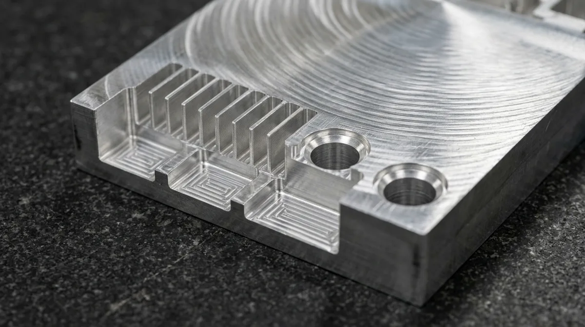
To validate CNC milling kinematics, dynamic feed rates, and chip evacuation strategies before committing to production tooling, machine shops utilize standardized aluminum DFM benchmark coupons. High-speed 3-axis and 4-axis vertical machining centers (VMCs) perform rapid trochoidal pocketing and peripheral contouring to evaluate cutting forces across varying wall thicknesses and pocket depths. High-pressure flood coolant delivered directly to the cutting flutes flushes chips away instantaneously, eliminating heat buildup and material adhesion.
Cutting Tool Geometry & Coating Selection
The physical affinity between aluminum and tungsten carbide tool binders can cause aluminum to weld onto the tool rake face, leading to catastrophic tool failure and torn surface finishes. To eliminate built-up edge (BUE), cutting tools must incorporate specific geometric attributes:
- Rake & Relief Angles: Specify high positive radial rake angles (15°–25°) and sharp cutting edges. High rake angles shear aluminum chips cleanly with minimal cutting pressure, reducing heat input into the workpiece.
- Mirror-Polished Flutes: Flute surfaces must be micro-polished to an optical mirror finish (Ra < 0.05 μm). Ultra-smooth flutes drastically reduce chip sliding friction, enabling rapid evacuation during high-speed trochoidal milling.
- Flute Count:
- 2-Flute End Mills: Deliver maximum chip gullet clearance, ideal for deep pocket roughing, heavy slotting, and gummy alloys (5052, 1100).
- 3-Flute End Mills: Provide optimal balance of core tool rigidity and chip space. Ideal for high-speed dynamic milling and peripheral finishing in 6061 and 7075.
- ≥ 4-Flute End Mills: Restricted to light peripheral finish skimming only; pocketing with 4 or more flutes causes chip packing and cutter breakage in aluminum.
- Tool Coatings: Standard TiN or TiAlN coatings contain titanium and aluminum, which chemically bond with hot aluminum chips. For aluminum CNC milling, use uncoated polished carbide or specialized Diamond-Like Carbon (DLC) coatings. For highly abrasive high-silicon cast alloys (>10% Si) or metal-matrix composites, Polycrystalline Diamond (PCD) tipped tooling provides extended tool life.
| Operation | 6061-T651 Surface Speed vc (m/min) | 7075-T651 Surface Speed vc (m/min) | Chip Load fz (Ø12mm Tool, mm/tooth) | Axial Depth ap | Radial Width ae |
|---|---|---|---|---|---|
| Dynamic Roughing (HSM) | 600 – 1,200 | 500 – 900 | 0.15 – 0.25 | 1.5 – 2.5 × D | 0.08 – 0.15 × D |
| Slotting / Full Pocketing | 350 – 600 | 300 – 500 | 0.08 – 0.14 | 0.5 – 1.0 × D | 1.0 × D |
| Side Wall Finishing | 800 – 1,500 | 600 – 1,100 | 0.05 – 0.10 | 1.0 – 2.0 × D | 0.02 – 0.05 × D |
| Face Milling (Fly Cutter) | 1,000 – 2,500 | 800 – 1,800 | 0.10 – 0.20 | 0.5 – 1.5 mm | 0.65 – 0.80 × D |
| Carbide Drilling | 150 – 250 | 120 – 200 | 0.12 – 0.28 (mm/rev) | Through / Blind | 1.0 × Drill Ø |
4. Thermal Management, Distortion Control & DFM Guidelines
The primary challenge when CNC machining thin-walled, asymmetric, or high-aspect-ratio aluminum components is post-machining dimensional distortion. Aluminum alloys feature a linear coefficient of thermal expansion (α ≈ 23 × 10−6/K)—nearly double that of carbon steel (α ≈ 11.5 × 10⁻⁶/K). A temperature rise of just 15°C during heavy roughing can cause a 300 mm aluminum plate to expand by over 0.10 mm:
ΔL = α × L0 × ΔT = (23 × 10−6 K−1) × 300 mm × 15 K = 0.1035 mm
When the component cools back to the 20°C ambient inspection temperature, it shrinks below nominal drawing dimensions, leading to out-of-tolerance rejections. Mitigating thermal distortion requires high-pressure through-spindle coolant delivery (50–70 bar) utilizing semi-synthetic water-soluble emulsions (concentration maintained strictly at 8%–10% Brix) to ensure instantaneous heat dissipation at the shear zone.
Controlling Machining-Induced Residual Stress
When machining large aerospace pockets or hogging out over 70% of a raw billet’s volume, asymmetric material removal upsets the equilibrium of internal residual stresses, producing severe part bowing (the “banana effect”). To eliminate warping and ensure sub-0.02 mm flatness across large plates, our machine shop enforces a 4-step stress management protocol:
- Specify Stretched Billets (T651/T7351): Always procure plate conforming to ASTM B209 with controlled stretching relief. Never use extruded bars or standard T6 stock for deep-pocket components.
- Symmetric Material Removal: Rough Side A, leaving 0.5 mm to 0.8 mm stock on all surfaces. Flip the part and rough Side B symmetrically. This balances stress release across the neutral axis.
- Intermediate De-Clamping & Stress Relief: Release primary high-force clamping vises. Allow the component to rest freely on the fixture plate for 15–30 minutes to permit natural stress relaxation.
- Torque-Controlled Re-Clamping & Finish Pass: Re-clamp using calibrated torque wrenches or vacuum fixture chucking with minimal holding force (just sufficient to overcome finishing tool cutting thrust). Execute finishing toolpaths at maximum spindle speed and light radial step-overs.
Core DFM Rules for Aluminum CNC Components
- Internal Pocket Corner Radii: Never design sharp 90° inside vertical corners. Specify internal radii R ≥ 0.25 × pocket depth. Furthermore, always make the drawing corner radius at least 0.5 mm larger than the standard milling cutter radius (e.g., specify R3.5 mm for a Ø6 mm tool) to prevent cutter jamming, severe tool deflection, and chatter marks in corners.
- Minimum Wall & Floor Thickness: Unsupported vertical walls should maintain a minimum thickness t ≥ 0.8 mm; for tall walls, enforce an aspect ratio of height-to-thickness H/t ≤ 8:1 to prevent vibrational harmonic chatter. Floor sections should maintain t ≥ 1.0 mm to prevent breakthrough under tool axial thrust.
- Thread Engagement Depth: Aluminum is softer than steel fasteners. Enforce minimum thread engagement lengths of 1.5 × nominal bolt diameter for 6061-T651 and 2.0 × diameter for softer 5052-H32. Whenever possible, utilize fluteless roll forming taps instead of cutting taps; cold forming compresses the aluminum grain structure, yielding 30% higher shear pull-out strength without generating chips inside blind holes.
- Deep Cavity Aspect Ratios: Limit pocket depths to ≤ 4 × cutter diameter. Pockets exceeding 4:1 depth-to-diameter ratios require long-reach tool holders, which suffer from exponential tool tip deflection (δ ∝ L3 / [E · I]), forcing significant reductions in cutting feeds and increasing cycle times.
5. Surface Finishing, Anodizing Tolerancing & Corrosion Protection
Raw CNC machined aluminum components naturally form a microscopic, passive aluminum oxide film (Al2O3) approximately 2–5 nanometers thick upon exposure to atmospheric oxygen. While this native film provides baseline protection against clean ambient air, it is porous and readily compromised by halides, acidic moisture, or mechanical abrasion. Industrial applications demand engineered surface treatments to enhance wear resistance, corrosion protection, electrical grounding, or cosmetic appearance.
The Dimensional Physics of Anodizing: Growth vs. Penetration
Unlike electroplated coatings (such as chrome or nickel) that deposit entirely onto the external metal surface, anodic oxidation transforms the aluminum substrate electrochemically into an amorphous aluminum oxide ceramic layer. This chemical transformation follows a fundamental physical rule:
Anodizing Dimensional Shift: 50% Penetration into Substrate & 50% Outward Growth
Understanding this 50/50 ratio is essential for managing precision tolerances on bearing bores, dowel pin holes, and threaded features:
- MIL-A-8625 Type II (Sulfuric Acid Anodizing): Typical total coating thickness ranges from 8 μm to 25 μm (0.008–0.025 mm). With 50% outward growth, an external shaft diameter increases by 8–25 μm (+0.008 to +0.025 mm total OD). Conversely, an internal bore diameter decreases by the same amount (−0.008 to −0.025 mm total ID). Available in clear or dyed colors (black, blue, red, gold).
- MIL-A-8625 Type III (Hardcoat Anodizing): Conducted at near-freezing electrolyte temperatures (0°–4°C) and high current densities to produce an ultra-dense ceramic coating 40 μm to 50 μm thick. Delivers surface hardness comparable to hardened steel (≈ 400–500 HV, roughly 45–50 HRC equivalent). However, outward growth adds 20–25 μm per surface, which will cause precision H7 reamed holes or class 6H threads to seize if not properly compensated for in pre-machining dimensions.
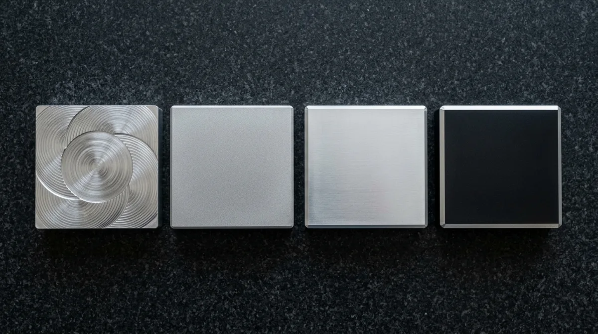
Achieving consistent visual appearance and precise dimensional compliance across machined aluminum components requires careful selection of pre-treatment and anodizing parameters. Standardized engineering test coupons evaluate the tactile and visual progression from as-machined circular toolpath milling to fine bead blasting, Type II sulfuric clear anodizing, and MIL-A-8625 Type III black hardcoat anodizing. Resting flat on an inspection granite surface, each finish demonstrates the controlled transition from raw metal to a dense, wear-resistant protective oxide layer.
| Finishing Process | Specification Standard | Typical Thickness | Dimensional Change per Surface | Corrosion Resistance (ASTM B117) | Surface Hardness | Electrical Conductivity |
|---|---|---|---|---|---|---|
| As-Machined (Standard) | ISO 4287 (Ra 1.6 μm) | None | ±0.000 mm | < 24 Hours | Base Metal (60–150 HBW) | Fully Conductive |
| Bead Blasting (#120) | Satin Matte (Ra 1.2–2.0) | None (Subtractive) | −0.002 to −0.005 mm | < 24 Hours | Base Metal | Fully Conductive |
| Type II Anodize (Class 1/2) | MIL-A-8625 Type II | 8 – 25 μm | +0.004 to +0.012 mm | 336 – 1,000 Hours | 300 – 350 HV | Non-Conductive (Insulator) |
| Type III Hardcoat Anodize | MIL-A-8625 Type III | 40 – 50 μm | +0.020 to +0.025 mm | 1,000 – 2,000 Hours | 400 – 500 HV (≈ 45–50 HRC) | High Dielectric Strength |
| Chemical Film (Alodine) | MIL-DTL-5541 Type II | < 1 μm | Negligible (< 0.001 mm) | 168 – 336 Hours | Base Metal | Conductive (EMI/RFI Shielding) |
| Electroless Nickel (ENP) | ASTM B733 | 10 – 30 μm | +0.010 to +0.030 mm | 500 – 1,000 Hours | 500 – 1,000 HV (Heat Treated) | Fully Conductive |
6. Quality Assurance, Geometric Tolerancing & Metrology Protocols
Dimensional verification of precision aluminum components requires comprehensive metrology tools capable of validating complex Geometric Dimensioning and Tolerancing (GD&T) schemes across varying temperatures. General machining dimensions adhere to ISO 2768-mK standards for linear and angular features. Critical mating interfaces—such as bearing journals, guide rail locating faces, and dowel pin bores—are directly held to numerical drawing tolerances of ±0.010 mm to ±0.020 mm. For ultra-precision hydraulic valves or slide components, wire EDM and precision jig grinding achieve ±0.005 mm.
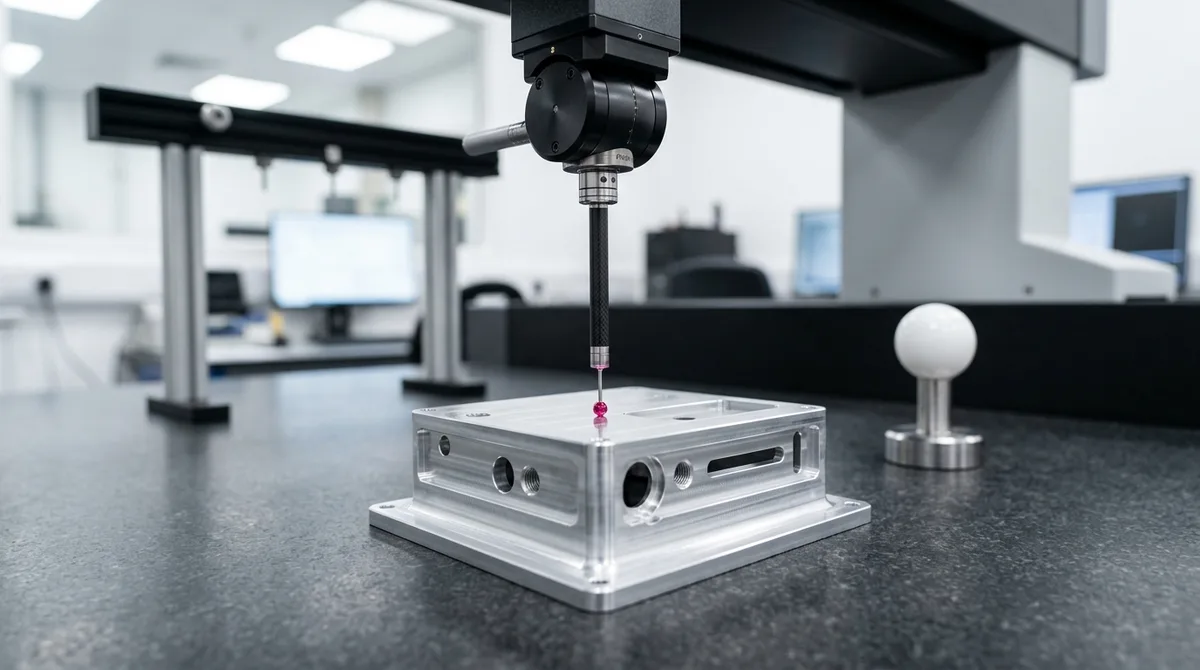
To verify complex geometric tolerances without introducing operator measurement variance, precision machined aluminum housings undergo First Article Inspection (FAI) on coordinate measuring machines (CMM) in an environmentally controlled metrology cleanroom held at 20°C ± 0.5°C. Calibrated ruby touch trigger probes contact primary datum surface A to establish reference planes, verifying flatness, bore concentricity, and true position callouts down to ±0.010 mm against native 3D CAD geometry.
Comprehensive Quality & Material Documentation
- Traceable Material Test Reports (MTR): Complete EN 10204 Type 3.1 mill test documentation accompanies raw billets, verifying chemical spectrometry analysis, mechanical tensile yield, ultimate tensile strength, and percentage elongation.
- First Article Inspection (FAI): Complete Comprehensive First Article Inspection (FAI) documentation correlating ballooned 2D engineering drawings with 100% measured dimensional data across initial prototype runs.
- Surface Roughness Profilometry: Calibrated diamond-stylus profilometers verify surface finish parameters (Ra, Rz) per ISO 4287 standards, ensuring sealing surfaces meet required leak-tight micro-finishes.
- Hardness Testing: Benchtop Rockwell (HRB) and portable Webster/Brinell hardness testers verify that solution heat-treatment and artificial aging cycles meet temper specifications before shipping.
7. Engineering Selection Framework: Selecting the Optimal Aluminum Alloy
When evaluating aluminum alloys for a new hardware development program, engineering teams should follow a structured decision hierarchy that balances functional mechanical requirements against manufacturability and cost drivers:
- Define the Primary Loading Environment:
- Static high mechanical load: Select 7075-T651 (highest strength-to-weight ratio).
- Dynamic cyclic fatigue / tension: Select 2024-T351 (superior crack growth resistance).
- General structural rigidity & mounting: Select 6061-T651 (most economical and readily available).
- Assess Environmental Exposure & Corrosion Risk:
- Salt water, marine, or harsh outdoor immersion: Select 5052-H32 (unwelded or welded) or 6061-T651 with MIL-A-8625 Type III Hardcoat. Avoid 2024.
- High-stress corrosive atmospheres: Select 7075-T7351 or 7050-T7451 to prevent stress-corrosion cracking.
- Evaluate Joining & Assembly Methods:
- TIG/MIG Fusion Welding: Specify 6061 or 5052. Never specify 7075 or 2024 for fusion-welded assemblies due to hot micro-cracking in the heat-affected zone (HAZ).
- Bolted / Pinned Assemblies: 6061-T651, 7075-T651, and 2024-T351 are all fully suitable; specify roll-formed threads or stainless steel wire helical inserts (Heli-Coil) for high-torque cyclic fastening.
- Determine Surface Aesthetics & Dimensional Tolerances:
- Vibrant cosmetic color anodizing: 6061-T651 or 6063-T6 produce bright, uniform colors.
- Ultra-hard abrasive wear resistance: Specify 6061-T651 or 7075-T651 with MIL-A-8625 Type III Hardcoat, factoring in 50% outward thickness growth on critical dimensions.
- Electrically conductive EMI/RFI shielding: Specify MIL-DTL-5541 Type II chemical conversion film on 6061-T651.
Frequently Asked Questions
Standard 6061-T6 retains significant internal thermal residual stresses induced during water quenching from the solution heat-treat furnace. When a CNC milling cutter removes substantial material from one side of a T6 block, this residual stress balance is disrupted, causing the workpiece to bow, twist, or cup (“banana effect”). The T651 temper incorporates a controlled mechanical stretch of 1.5% to 3.0% permanent set after quenching, which mechanically unloads and neutralizes internal residual stresses, ensuring exceptional dimensional stability during aggressive roughing.
MIL-A-8625 Type III hardcoat anodizing penetrates 50% into the aluminum substrate and builds up 50% above the original surface. A standard 50 μm (0.050 mm) hardcoat layer creates 25 μm (0.025 mm) of outward growth per surface. Consequently, external shaft diameters increase by 0.050 mm (+0.025 mm per side), while internal hole and bore diameters decrease by 0.050 mm (−0.025 mm per side). Critical bearing bores, reamed pin holes, and fine threads must either be pre-machined oversized/undersized to compensate for growth or masked using precision silicone plugs during chemical processing.
While 7075-T651 provides peak tensile yield strength (≥ 503 MPa), it is highly susceptible to intergranular stress-corrosion cracking (SCC) when subjected to sustained tensile stresses in humid, marine, or industrial environments. The T7351 temper utilizes a proprietary two-stage overaging thermal cycle that alters grain boundary precipitates, virtually eliminating SCC susceptibility. Although T7351 sacrifices approximately 10% to 15% of peak yield strength (≈ 435 MPa), it is strongly recommended for mission-critical aerospace, military, and subsea structures operating under continuous tensile pre-loads.
Built-up edge occurs when hot aluminum chips weld to the cutting edge due to friction and high cutting pressure. Preventing BUE requires: (1) using sub-micron carbide tools with high positive rake angles (15°–25°) and mirror-polished flutes (Ra < 0.05 μm); (2) avoiding titanium-based coatings like TiN or TiAlN, instead using uncoated polished carbide or Diamond-Like Carbon (DLC) coatings; (3) maintaining high chip loads (fz ≥ 0.10 mm/tooth) to ensure heat leaves with the chip rather than transferring into the tool; and (4) delivering high-pressure, water-soluble flood coolant directly into the cut zone.
Generally, no. Standard fusion welding methods (TIG or MIG) should not be performed on 7075 aluminum. The high zinc and copper content creates extreme hot-cracking sensitivity in the weld pool and severe micro-porosity in the heat-affected zone (HAZ), resulting in dramatic joint strength reduction and immediate susceptibility to stress corrosion. If an assembly requires structural welding alongside high strength, engineers should specify 6061-T651 (welded then re-heat treated) or high-magnesium 5083/5052 alloys instead of 7075.
Request an Engineering DFM Review for Precision Aluminum Machining
Need tight-tolerance CNC milled, turned, or 5-axis contoured aluminum components? AS Prototypes provides agile prototyping and low-volume production with general ISO 2768-mK tolerances and tight tolerances down to ±0.010 mm (±0.0004″) on critical datum features. Our engineering team conducts comprehensive Design for Manufacturing (DFM) reviews within 24 hours, supported by verified Mill Material Test Reports (MTR), full in-house MIL-spec anodizing, and Zeiss CMM metrology verification.







