


- Monolithic Unibody Subtractive Kinematics: Precision aluminum phone housing CNC machining transforms a solid 400-gram extruded aluminum billet into a rigid 28-gram structural chassis, evacuating over 92% of the parent raw metal while maintaining critical wall thicknesses down to 0.60 mm (±0.015 mm).
- Alloy Metallurgy & Optical Anodizing: 6063-T651 serves as the gold standard for velvet satin anodizing due to minimal iron (Fe < 0.35%) and silicon impurities, preventing optical hazing; 6013-T6 and 6061-T651 provide elevated yield strength (up to 330 MPa) for drop-impact resistance; 7075-T651 offers aerospace-grade rigidity (>500 MPa yield) but requires low-temperature, low-voltage electrolytic baths to avoid zinc galvanic pitting.
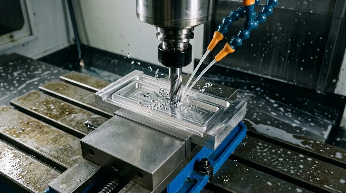
- Shop-Floor Machine Tool Workhorse: High-speed 3-axis and 4-axis立式钻攻中心/加工中心 (VMCs with 24,000 to 30,000 RPM BT30/HSK spindles) represent 75% to 85%+ of dedicated chassis production capacity. Simultaneous 5-axis milling is strategically deployed for complex 3D curved corners, camera island transitions, and compound-angled side ports.
- Nano-Molding Technology (NMT) for RF Bands: CNC micro-endmills cut 0.8 to 1.2 mm antenna isolation slits, followed by chemical T-treatment nano-etching (20 to 30 nm re-entrant pores) and high-pressure injection of PPS/PBT engineering plastic, generating molecular-level mechanical interlocking with shear bond strength exceeding 20 MPa and an IP68 hermetic seal.
- Distortion Management & Vacuum Clamping: Thin floor deflection under cutting forces is eliminated using multi-chamber vacuum chucks with UV-curable water-soluble acrylic adhesives and symmetrical balanced roughing passes to counteract residual quench stress release.
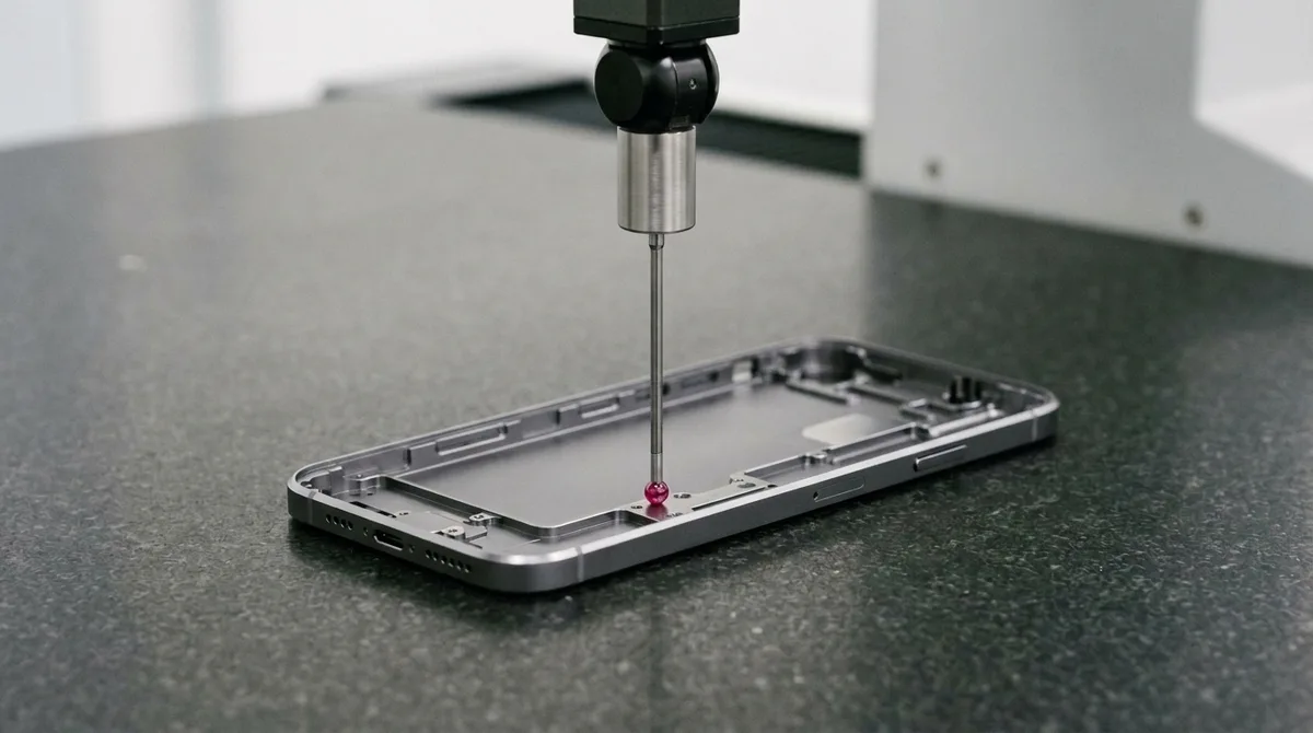
- Coordinate Metrology & GD&T Standards: Precision components are verified on bridge-type Zeiss Coordinate Measuring Machines (CMM) with motorized ruby scanning probes, adhering to ISO 2768-mK general tolerances and holding critical mating features, bearing bores, and display glass ledges to ±0.010 mm to ±0.020 mm.
In high-end consumer electronics, ruggedized field tablets, and handheld medical instrumentation, the external mechanical enclosure defines the user experience, structural survival, and thermal management. While stamped sheet metal and thin-wall plastic injection molding dominate budget hardware, flagship electronic devices demand the torsion-resistant chassis rigidity, thermal conductivity, cool metallic hand-feel, and seamless aesthetic perfection of an all-metal unibody chassis. Monolithic chassis engineering eliminates flimsy snapped seams, maximizing internal battery volume and shielding delicate logic boards.
Executing precision aluminum phone housing CNC machining requires orchestrating high-speed cutter kinematics, advanced metallurgy, nano-scale chemical bonding, and microscopic surface finishing. Manufacturing an enclosure where the finished part represents less than 8% of the initial raw extruded billet demands comprehensive control over residual material stress relief, dynamic tool deflection, and micro-machining tolerances held to ±0.010 mm across multi-station setups.
- 1. Mechanical Anatomy & Engineering Requirements of a Smartphone Unibody
- 2. Metallurgy & Alloy Selection: 6000-Series vs. 7000-Series Aluminum
- 3. The 5-Station CNC Machining Architecture: From 400g Billet to 28g Chassis
- 4. Nano-Molding Technology (NMT): Hermetic Antenna RF Integration
- 5. Thin-Wall Mechanics, Vacuum Fixturing & Residual Stress Warpage Control
- 6. Precision Port Machining & Single-Crystal Diamond Chamfering
- 7. Multi-Stage Surface Finishing: Automated Blasting & Velvet Satin Anodizing
- 8. Metrology, GD&T & Coordinate Measuring Machine (CMM) Verification
- 9. DFM Architecture & Precision Machining Tolerance Matrix
- 10. Manufacturing Architecture Comparison: CNC Billet vs. Die Casting vs. Stamping
- 11. Frequently Asked Questions (FAQ)
1. Mechanical Anatomy & Engineering Requirements of a Smartphone Unibody
A flagship smartphone unibody enclosure serves as both the primary structural exoskeleton and the core thermal radiator of the mobile device. In traditional three-piece smartphone architectures, an internal die-cast magnesium midframe is sandwiched between a front glass digitizer and a plastic or glass rear panel. While modular, this legacy approach introduces multiple joint interfaces, mechanical creaks, thermal boundary resistance, and thicker overall device profiles.
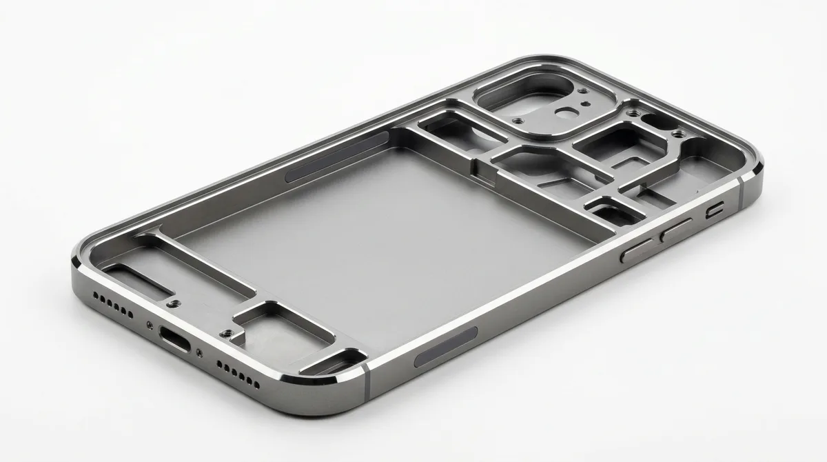
Modern monolithic unibody enclosures integrate the perimeter sidewalls, internal component dividing bulkheads, threaded standoff bosses, speaker acoustic chambers, and rear exterior shell into a single continuous piece of structural aluminum alloy. This monolithic architecture maximizes the internal volumetric packaging efficiency, allowing engineers to dedicate more space to high-capacity lithium-ion polymer batteries and multi-lens optical periscope camera assemblies while maintaining a sleek, sub-8.0 mm chassis thickness.
From a mechanical perspective, the aluminum enclosure must withstand severe torsional bending loads and survive standardized 1.5-meter to 2.0-meter multi-angle drop tests onto steel plates without permanent plastic deformation. Simultaneously, the enclosure functions as an isotropic heat spreader, rapidly conducting thermal energy away from high-density multi-core mobile processors and power management integrated circuits (PMICs) through internal graphite heat pipes directly to the outer aluminum surface.
The manufacturing challenge lies in the sheer volume of metal removal. A standard extruded billet weighing approximately 400 grams is progressively machined until only 28 to 32 grams of intricate metal skeleton remains. Removing over 92% of the material inevitably releases deep internal residual stresses that can warp thin 0.6 mm floors, distort perimeter display bonding ledges, and compromise hermetic IP68 water resistance if machining dynamics are not tightly governed.
2. Metallurgy & Alloy Selection: 6000-Series vs. 7000-Series Aluminum
Selecting the optimal aluminum alloy for handheld unibody manufacturing involves balancing mechanical yield strength, fracture toughness, high-speed CNC machinability, and optical anodizing response. Because consumer electronics are scrutinized directly under bright ambient lighting, optical surface clarity after sulfuric acid anodizing is as critical as tensile yield strength.
6000-Series Alloys (Al-Mg-Si): The Optical Finishing Standard
6000-series aluminum alloys rely on magnesium silicide (Mg2Si) precipitate hardening. These alloys offer exceptional plastic formability during raw billet extrusion, outstanding corrosion resistance, and predictable chip formation during high-speed milling operations.
6063-T651 Aluminum: Revered across the consumer electronics industry as the premier grade for satin architectural and cosmetic anodizing. 6063 maintains exceptionally tight metallurgical limits on iron (Fe < 0.35%) and silicon (Si 0.20% to 0.60%). Iron intermetallic phases such as Al3Fe and AlFeSi scatter light and create visible milky streaks or dark pinpoints under transparent anodized coatings. With ultra-low iron purity, 6063 produces an optically flawless, glass-like alumina layer with vibrant color saturation. However, its moderate yield strength (≈ 215 MPa) makes it susceptible to localized denting during severe impact.
6013-T6 / 6061-T651 Aluminum: To address the yield strength limitations of 6063, aerospace-developed 6013 introduces controlled additions of copper (0.6% to 1.1%), silicon (0.6% to 1.0%), and magnesium (0.8% to 1.2%). This composition accelerates precipitate nucleation during artificial aging, boosting yield strength to over 330 MPa—a 53% increase over 6063. This elevated strength provides excellent resistance against chassis bending and pocket-crush loads while maintaining clean high-speed cutting dynamics and uniform anodizing color reception.
7000-Series Alloys (Al-Zn-Mg-Cu): Maximum Structural Hardness
7000-series alloys are precipitation-hardened by the η-phase (MgZn2) and represent the peak of commercial aluminum mechanical strength. When hardware designers require zero-flex chassis rigidity for ultra-thin foldable devices or heavy rugged industrial data collectors, 7000-series alloys are the premier metallurgical choice.
7075-T651 Aluminum: Yielding at over 503 MPa with an ultimate tensile strength exceeding 570 MPa, 7075 delivers structural performance comparable to structural steels at one-third the density. A unibody machined from 7075-T651 is virtually immune to permanent bending under standard 4-point flexure testing. However, 7075 presents specific surface engineering constraints: its high zinc (5.1% to 6.1%) and copper (1.2% to 2.0%) content forms galvanic micro-couples in standard sulfuric acid anodizing electrolytes. If bath temperature rises above 20°C, localized galvanic etching produces yellowish clouding and microscopic pits. Consequently, 7075 anodizing demands tightly refrigerated baths (14°C to 16°C) and specialized organic acid buffering agents.
7003-T6 Aluminum: Developed specifically as a weldable and extrudable Al-Zn-Mg alloy with reduced copper content (Cu < 0.20%). 7003 achieves a yield strength of 290 to 320 MPa, bridging the gap between 6013 and 7075 while providing substantially superior optical color consistency during decorative electrolytic dyeing.
| Alloy Grade & Temper | Key Alloying Elements | Yield Strength (MPa) | Tensile Strength (MPa) | Thermal Conductivity (W/m·K) | Anodizing Optical Clarity | Primary Device Application |
|---|---|---|---|---|---|---|
| 6063-T651 | Mg: 0.70%, Si: 0.40%, Fe < 0.35% | 215 | 245 | 201 | Pinnacle (Streak-free, deep velvet luster) | Flagship consumer smartphones, premium tablets |
| 6013-T6 | Mg: 1.0%, Si: 0.8%, Cu: 0.9% | 330 | 390 | 178 | Excellent (Minimal hazing, uniform saturation) | High-strength mobile frames, aerospace IoT units |
| 6061-T651 | Mg: 1.0%, Si: 0.6%, Cu: 0.28% | 276 | 310 | 167 | Very Good (Standard commercial consistency) | Rugged field electronics, medical handhelds |
| 7003-T6 | Zn: 5.5%, Mg: 0.8%, Cu < 0.20% | 310 | 360 | 155 | Good (Requires tight electrolyte control) | Impact-resistant smartphone chassis, foldables |
| 7075-T651 | Zn: 5.6%, Mg: 2.5%, Cu: 1.6% | 503 | 572 | 130 | Moderate (Demands low-temp chilled baths) | Defense-grade terminals, drop-proof chassis |
3. The 5-Station CNC Machining Architecture: From 400g Billet to 28g Chassis
Producing a smartphone unibody enclosure from solid aluminum requires a multi-station sequential manufacturing line. A single continuous CNC setup is impossible due to the necessity of flipping the component, machining perimeter split-lines for antenna isolation, and performing intermediate nano-molding and stress-relief operations.
In high-volume precision manufacturing, high-speed 3-axis and 4-axis立式钻攻中心 (VMCs with BT30/HSK spindles operating at 24,000 to 30,000 RPM) represent 75% to 85%+ of dedicated production capacity. These specialized tapping and milling centers provide ultra-fast axis acceleration (up to 1.5G to 2.0G) and sub-second tool changes, delivering maximum cutting productivity. Five-axis centers are integrated strategically at dedicated stations to machine compound side apertures, angled camera bezels, and 3D flowing perimeter blends.
Station 1: External Profiling & Sacrificial Clamping Tabs (CNC-1)
The raw stock begins as a precision saw-cut rectangular extrusion bar (typically 170 mm × 85 mm × 12 mm). The billet is clamped along its bottom perimeter in a multi-station pneumatic vise.
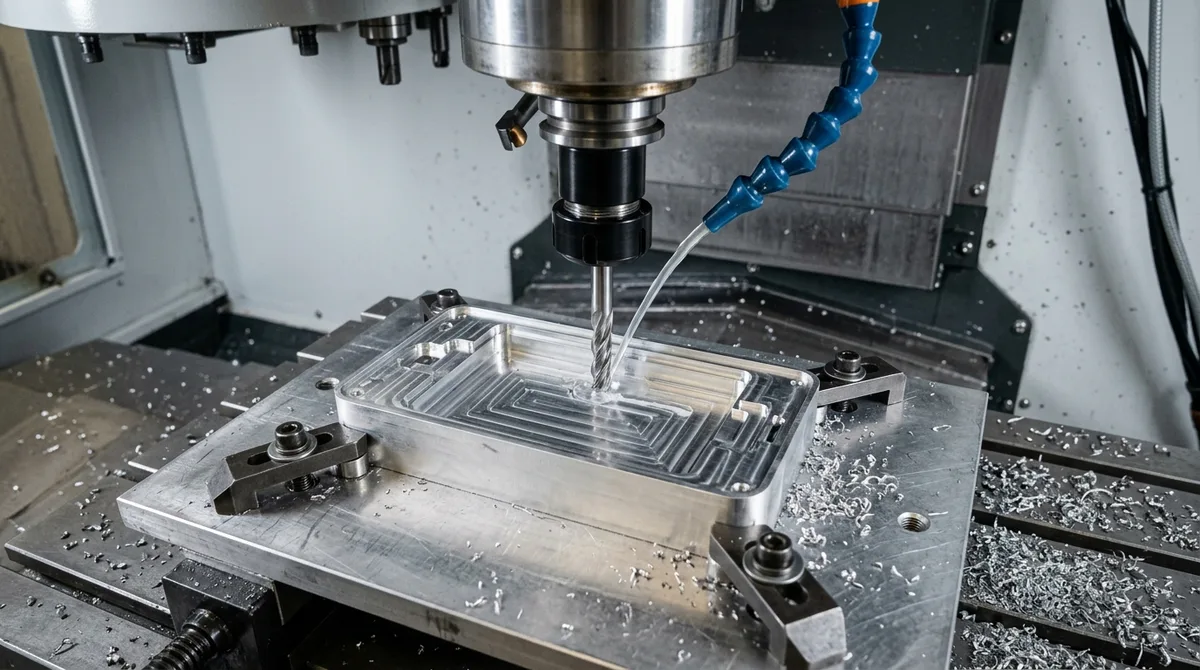
High-speed solid carbide face mills (Ø50 mm, 5 flutes, 12,000 RPM) skim the top surface to establish primary Datum A. High-speed bull-nose endmills (Ø10 mm, R1.0 mm, 24,000 RPM) sculpt the 3D ergonomic exterior curvature of the rear shell, transitional corner radii, and perimeter chamfers. Concurrently, peripheral cutters mill two sacrificial clamping rails and four precision locating pin holes (Ø3.0 mm H7) into the bottom perimeter tabs, which will serve as the geometric locating datums for all subsequent setups.
Station 2: Internal Bulk Cavity Evacuation & Roughing (CNC-2)
The billet is inverted and seated onto hardened steel locating pins engaging the Station 1 datum holes, clamped rigidly from the top sacrificial perimeter tabs.
Station 2 executes the most aggressive metal removal phase of the entire process, carving out the massive internal hollows: the primary battery compartment, the motherboard and logic board recess, the multi-lens optical image stabilization (OIS) camera housing, the speaker resonant acoustic chamber, and the vibration actuator cavity. Adaptive high-feed trochoidal clearing paths maintain a constant tool radial engagement (ae = 8% to 12% of tool diameter) at axial depths of ap = 2.0D. Using dense synthetic flood emulsion (8% to 10% oil concentration, 20 bar pressure), cutting chips are evacuated instantly to prevent chip packing and localized thermal buildup. Station 2 leaves a uniform 0.35 mm finishing allowance across all internal floors and walls.
Station 3: Antenna Slot Slitting & Nano-Molding Preparation (CNC-3)
Before the internal cavities can be micro-finished to their final nominal 0.6 mm wall thickness, the unibody must be prepared for antenna isolation. Solid metal blocks radio frequency propagation; therefore, the outer perimeter frame must be strategically severed.
Solid carbide micro-slitting cutters and high-precision Ø1.0 mm endmills machine continuous 0.8 mm to 1.2 mm wide antenna isolation slits through the perimeter rim. These slits physically isolate distinct metallic zones of the frame, transforming them into cellular, Wi-Fi, and GPS antenna radiators. The part is then unmounted for chemical nano-etching and plastic insert injection molding (NMT), detailed in Section 4.
Station 4: Thin-Floor Finishing & Side Feature Machining (CNC-4)
Following plastic injection molding and deflashing, the hybrid metal-plastic chassis returns to CNC Station 4. At this stage, the external datum tabs are severed, and the workpiece is seated into a customized vacuum nest that supports every square millimeter of the thin floor.
Micro-endmills (Ø2.0 mm and Ø1.5 mm DLC-coated carbide tools) finish the battery and logic board floor thicknesses down to 0.60 mm (±0.015 mm). Dedicated 4th-axis rotary indexers and compact right-angle spindle heads machine the side-key apertures (power button, volume rocker), the SIM card tray slot, the USB-C interface port, and the acoustic speaker grille perforations (an array of micro-holes down to Ø0.8 mm).
Station 5: Single-Crystal Diamond Chamfering (MCD / SPDT) (CNC-5)
The final subtractive operation executes the iconic mirror-bright specular chamfers that frame the perimeter of the unibody and highlight the camera module housing. Single-point monocrystalline diamond (MCD) fly-cutters rotate at 24,000 RPM to shave a microscopic 0.25 mm bevel at 45 degrees, detailed in Section 6.
| Station | Machine Configuration | Primary Manufacturing Operation | Typical Cutting Tools | Critical Tolerances | Workholding Method |
|---|---|---|---|---|---|
| CNC Station 1 | 3-Axis High-Speed VMC (24,000 RPM) | Datum A facing, exterior 3D curvature, clamping tabs | Ø50mm face mill, Ø10mm bull-nose endmill | Datum A flatness ≤ 0.020 mm | Pneumatic perimeter vise jaws |
| CNC Station 2 | 3-Axis High-Speed VMC (30,000 RPM) | Internal bulk pocketing (battery, logic, camera) | Ø6mm & Ø8mm 3-flute adaptive roughers | Pocket depth ±0.025 mm | Locating pins + perimeter clamps |
| CNC Station 3 | 3-Axis / 4-Axis Drilling Center | Antenna isolation slit milling, NMT gate wells | Ø1.0mm micro-endmills, slitting saws | Slit width ±0.015 mm | Hydraulic internal expanding fixture |
| CNC Station 4 | 4-Axis / 5-Axis Multi-Head VMC | 0.6mm floor micro-finishing, USB-C & SIM slots | Ø1.5mm DLC endmills, right-angle heads | Wall thickness ±0.015 mm | Vacuum chuck + UV adhesive backing |
| CNC Station 5 | Ultra-Precision SPDT CNC Mill | Single-crystal diamond perimeter chamfering | Monocrystalline natural diamond fly-cutter | Chamfer width ±0.010 mm, Ra < 0.015 μm | High-precision contour vacuum nest |
4. Nano-Molding Technology (NMT): Hermetic Antenna RF Integration
The fundamental physical conflict of an all-metal smartphone chassis is electromagnetic attenuation: a continuous aluminum enclosure acts as an impenetrable Faraday cage, completely blocking high-frequency cellular (5G NR Sub-6 and mmWave), Wi-Fi 6E/7, Bluetooth 5.3, GNSS, and Near-Field Communication (NFC) signals. To restore radio transparency, hardware architects partition the perimeter aluminum frame into tuned electromagnetic resonating segments, physically separated by thin dielectric plastic bands.
Historically, early smartphones bonded plastic antenna inserts into milled aluminum gaps using structural epoxy or polyurethane adhesives. However, glued joints suffered catastrophic adhesive failure under thermal cycling (-20°C to +60°C) and torsional shock, compromising the structural frame and breaching IP67/IP68 water ingress seals. Modern unibody manufacturing resolves this via Nano-Molding Technology (NMT)—a hybrid metallurgical-polymeric fusion process.
The Chemical T-Treatment Nano-Etching Mechanism
Following Station 3 antenna slitting, the degreased aluminum housing is immersed in a multi-stage chemical T-treatment bath. An initial mild alkaline dip cleanses native oxides, followed by immersion in a specialized aqueous organic amine or acidic fluoride formulation at 50°C to 60°C. This chemical reaction selectively dissolves grain boundaries and sub-grain dislocation nodes in the aluminum surface.
Rather than producing macroscopic roughness, the T-treatment generates a dense, uniform network of microscopic re-entrant pores across the aluminum surface. These pores measure approximately 20 to 30 nanometers in diameter, penetrating 100 to 200 nanometers into the aluminum substrate. Crucially, the pores exhibit an inverted funnel or dovetail geometry—the opening diameter at the surface is narrower than the internal cavity diameter.
High-Pressure Insert Injection Molding
The nano-etched aluminum unibody is preheated to 120°C to 140°C and loaded into a high-precision multi-cavity injection molding tool. The mold clamps around the antenna slits, and an engineered thermoplastic resin—predominantly polyphenylene sulfide (PPS) or polybutylene terephthalate (PBT) modified with glass-fiber reinforcement and elastomeric impact modifiers—is injected at temperatures between 290°C and 310°C under extreme hydraulic pressures of 1,200 to 1,500 bar.
Under these intense pressures, the molten low-viscosity polymer flows directly into the 20-nanometer surface pores. Upon cooling, the plastic locks physically into the re-entrant cavities, creating billions of nanoscale mechanical anchors per square millimeter. The resulting joint does not rely on chemical adhesion; it represents pure mechanical anchoring at the molecular level, delivering shear bond strengths exceeding 20 to 25 MPa.
Following injection, the unibody returns to CNC Station 4. High-speed carbide endmills machine away the molded plastic runner gates and flush-trim the polymer flush with the outer aluminum contour. The step height transition between the aluminum frame and the plastic antenna band is held to less than ±0.008 mm, creating a completely seamless, tactilely imperceptible transition that guarantees hermetic IP68 water and dust protection under differential pressure helium testing.
5. Thin-Wall Mechanics, Vacuum Fixturing & Residual Stress Warpage Control
The engineering paradox of smartphone unibody machining is the pursuit of razor-thin walls (0.55 mm to 0.65 mm) within an expansive 160 mm × 75 mm footprint. Carving such thin structures triggers severe structural instability, tool chatter, and residual stress distortion.
The Classical Mechanics of Thin-Plate Flexure
In classical Kirchhoff-Love thin-plate mechanics, the flexural rigidity D of an unsupported plate is governed by the material elastic modulus E, Poisson’s ratio ν, and—most critically—the cube of the wall thickness t:
D = (E · t³) / [12 · (1 – ν²)]
Because flexural stiffness scales with the third power of thickness, reducing an aluminum wall from 1.2 mm down to 0.6 mm does not merely halve its rigidity—it reduces its structural resistance to deflection by a staggering 87.5% (an eight-fold reduction in stiffness). Under dynamic cutting forces, an unsupported 0.6 mm aluminum floor acts like an elastic drumhead. Cutting vibrations induce severe resonance chatter, resulting in visible wavy surface washboards, micro-cracking, and wall thickness variations exceeding ±0.05 mm.
Advanced Vacuum Clamping & Phase-Change Backing
To machine micro-thin floors with tight ±0.015 mm tolerances, conventional edge clamping or mechanical jaws are completely unviable. Instead, precision manufacturing utilizes advanced vacuum fixturing and phase-change chemical backing:
Multi-Zone Microporous Vacuum Fixturing: The fixture nest is precision-machined from sintered microporous ceramic or hardened stainless steel, replicating the exact 3D exterior curvature of the unibody. An elastomeric perimeter O-ring seals the vacuum chamber, while localized vacuum ports pull a constant negative pressure of -95 kPa to -98 kPa. This pulls the thin floor uniformly against the ceramic nest, eliminating diaphragm flexure during vertical tool engagement.
UV-Curable Water-Soluble Resin Backing: For ultra-deep cavities or complex multi-tier battery steps, vacuum alone cannot dampen high-frequency radial harmonic chatter. Here, manufacturing engineers deploy UV-curable, water-soluble temporary filling adhesives (e.g., Aquabond or Light-Weld formulations). A liquid photopolymer is dispensed into the rough-machined cavity and exposed to 365 nm UV light for 15 to 30 seconds, instantly polymerizing into a rigid, non-compressible solid backing. The cutter mills through both the aluminum and the supporting resin as if cutting solid billet. Once machining finishes, immersing the housing in 60°C warm water completely dissolves the resin within 3 minutes, leaving zero residue and zero mechanical deformation.
Neutralizing Residual Extrusion Stresses
Standard extruded aluminum bars contain substantial internal residual stresses induced during water quenching after hot extrusion. When heavy roughing removes 92% of the material asymmetrically, the internal stress equilibrium is shattered, causing the remaining thin floor to oil-can (bow outward or inward by up to 0.5 mm).
To eliminate warpage, unibody production enforces strict metallurgical and toolpath protocols: First, raw stock is mandated in the T651 stress-relieved temper, which undergoes 1.5% to 3.0% permanent plastic stretching after solution heat treatment to mechanically neutralize quench stresses. Second, CAM programmers implement symmetrical balanced milling paths: roughing passes alternate symmetrically from the center outward, balancing internal stress releases across the neutral bending axis. Finally, a semi-finishing rest dwell is introduced before final floor finishing, allowing the workpiece to equilibrate thermally to the 20°C flood coolant temperature.
| Structural Feature | Nominal Dimension | DFM Minimum Limit | Recommended Tooling & Strategy | Machining Tolerance | Failure Mode if Breached |
|---|---|---|---|---|---|
| Battery Cavity Floor | 0.60 mm | 0.50 mm (with stiffener ribs) | Ø2.0mm DLC endmill + vacuum chuck | ±0.015 mm | Diaphragm oil-canning, puncture under drop test |
| Perimeter Sidewall | 1.00 mm – 1.20 mm | 0.75 mm | Trochoidal sidewall profiling, short L/D | ±0.015 mm | Chassis bending, display glass adhesive popping |
| Display Bonding Ledge | 1.20 mm width × 0.25 mm depth | 0.90 mm width × 0.20 mm depth | Precision shoulder endmill (single pass) | ±0.010 mm | Glass digitizer proud or sunken, glue squeeze-out |
| Internal Corner Radii | R1.00 mm – R1.25 mm | R0.30 mm (USB/SIM slots) | Ø2.0mm endmill; Ø0.5mm micro-mill for slots | ±0.020 mm | Excessive tool wear, chatter marks, cutter breakage |
| Threaded Standoff Bosses | M1.4 × 0.3 thread (depth 2.5 mm) | M1.2 × 0.25 (depth 2.0 mm) | Form-tapping (roll tapping) without chips | Thread gauge 6H pass | Thread stripping under torque, chip contamination |
| Acoustic Speaker Holes | Ø0.80 mm | Ø0.50 mm | 40,000 RPM high-speed micro-drills | ±0.015 mm | Burr formation blocking acoustic mesh, drill break |
6. Precision Port Machining & Single-Crystal Diamond Chamfering
A flagship unibody enclosure features numerous intricate apertures penetrating its perimeter walls: the USB-C interface port, the mechanical SIM card tray slot, volume and power button pockets, and microphone sound ports. Machining these features through hardened aluminum and NMT plastic inserts requires specialized multi-axis toolheads.
Because the main spindle axis is perpendicular to the rear chassis face, side ports must be machined either via a 4th-axis rotary indexer rotating the housing 90 degrees or via high-speed right-angle aggregate spindle heads. USB-C ports present a unique challenge: the opening requires a rectangular profile with corner radii as small as R0.30 mm to accommodate standard connector shells. High-speed micro-endmills (Ø0.5 mm, 40,000 RPM air spindles) execute high-speed trochoidal contouring under dense air-oil mist to clear these tight corners without cutter breakage.
Monocrystalline Diamond Chamfering (MCD / SPDT) Mechanics
To elevate the enclosure from a utilitarian component to a luxury consumer product, designers integrate single-crystal diamond chamfers along the perimeter rim and around the camera module aperture. These mirror-bright, 45-degree specular highlights visually frame the satin-anodized chassis body.
Standard polycrystalline diamond (PCD) or tungsten carbide cutters cannot achieve this optical mirror effect. PCD consists of microscopic diamond grains bound by cobalt; microscopic grain boundaries along the cutting edge produce micro-scratches on aluminum. In contrast, Single-Crystal Monocrystalline Diamond (MCD) tools are ground from a single natural or high-pressure high-temperature (HPHT) synthetic diamond crystal along the {100} or {110} crystallographic plane.
The cutting edge of an MCD tool possesses zero grain boundaries, achieving a microscopic edge sharpness radius of ρ ≤ 20 nm. Operating at 20,000 to 28,000 RPM with a feed rate of 1,500 to 2,500 mm/min, the single-crystal diamond tool shears the aluminum alloy in the true ductile cutting regime. The metal is sheared smoothly without micro-tearing or brittle fracture, producing an optical surface finish with surface roughness Ra < 0.015 μm (SPI A-1 specular finish). Under ambient lighting, the diamond-cut bevel behaves like a polished optical prism, creating a stunning visual contrast against the surrounding satin bead-blasted surface.
7. Multi-Stage Surface Finishing: Automated Blasting & Velvet Satin Anodizing
The tactile sensation of a mobile unibody—its velvet-like warmth, resistance to skin oil fingerprints, and deep color saturation—is determined entirely by the post-machining surface treatment protocol. Even minute cutter scallop marks or microscopic tool passes will reflect light unevenly if surface preparation is executed incorrectly.
Step 1: Chemical Ultrasonic Degreasing & Micro-Etching
The fully machined housing is submerged in multi-frequency ultrasonic baths containing mild alkaline aqueous degreasers in deionized water at 55°C. This removes all traces of synthetic machining coolants, hydraulic oils, and handling residues. Next, a controlled chemical micro-etch in sodium hydroxide (NaOH, 40 to 50 g/L at 50°C for 20 to 30 seconds) dissolves a microscopic 1 to 2 μm layer of surface aluminum, rounding sharp micro-machining ridges without blunting critical functional edges. An immediate nitric acid desmutting bath (HNO3, 20% vol) strips away insoluble intermetallic alloying smut (iron, silicon, and copper precipitates).
Step 2: Robotic Multi-Axis Automated Zirconia Bead Blasting
Manual sandblasting is strictly banned in smartphone unibody production because human operators cannot maintain uniform nozzle distance, blast angle, and dwell time across complex curved surfaces. Variations of even 0.5 bar blasting pressure create visible dark patches after anodizing.
Automated unibody production deploys 6-axis robotic arms manipulating precision blast nozzles inside climate-controlled blast cabinets. Spherical ceramic zirconia (ZrO2) micro-beads (#280 to #320 mesh, diameter 45 to 63 μm) bombard the enclosure under a tightly regulated pneumatic pressure of 2.2 to 2.6 bar. Unlike angular aluminum oxide grit that cuts jagged micro-gouges, spherical zirconia beads deliver a micro-peening action, generating a dense, non-directional crater topography with an average surface roughness of Ra 0.65 to 0.85 μm. This diffuse matte micro-texture completely conceals underlying extrusion grain orientations and light reflections.
Step 3: MIL-A-8625 Type II Sulfuric Acid Anodizing
The bead-blasted unibody is racked onto precision titanium spring-finger fixtures and immersed in an electrochemical bath containing 160 to 180 g/L of sulfuric acid (H2SO4) and 5 to 10 g/L of dissolved aluminum ions. The bath temperature is maintained at 18.0°C ± 0.5°C using titanium immersion cooling coils and high-volume electrolyte circulation pumps.
Applying a constant current density of 1.2 to 1.5 A/dm² drives an electrochemical conversion reaction: oxygen ions migrate to the aluminum anode, growing a porous ceramic anodic oxide film (γ-Al2O3) directly from the parent metal to a calibrated depth of 12 to 18 μm. This anodic film consists of billions of hexagonal columnar cells, each containing a central nanopore measuring 12 to 15 nanometers in diameter.
Step 4: Nanoporous Organic Dyeing & Spectrophotometric Color Control
Immersing the unibody in computer-controlled organic or inorganic dye baths allows dye molecules to diffuse into the hexagonal nanopores. Color consistency across production lots is governed by spectrophotometric colorimetry under calibrated D65 retail daylight illuminants. The color variance between production batches is held strictly to ΔE ≤ 0.80 across the CIELAB color space, ensuring that separate production runs of Space Grey, Midnight Blue, or Champagne Gold are visually indistinguishable.
Step 5: Hydrothermal Nickel Acetate Sealing & Cold Laser Marking
To lock the dye molecules permanently inside the oxide film, the unibody is immersed in a deionized water solution containing nickel acetate hydrate (5 to 7 g/L) at 96°C to 98°C for 20 to 25 minutes. The high thermal energy hydrates the amorphous Al2O3 into crystalline boehmite (AlOOH), swelling the pore walls shut. Sealing delivers a sealed surface micro-hardness exceeding 350 HV, making the chassis highly resistant to coin abrasion, key scratches, and sweat-induced chemical degradation (surpassing 96 hours of ASTM B117 neutral salt spray exposure).
Finally, ultra-short pulse picosecond or femtosecond fiber lasers (1064 nm wavelength) engrave regulatory FCC/CE logos, device serialization, and internal 2D Data Matrix QR codes. The ultra-fast laser pulses ablate microscopic surface dye molecules via cold photochemical ablation without thermally scorching the surrounding anodic oxide layer.
8. Metrology, GD&T & Coordinate Measuring Machine (CMM) Verification
Validating an ultra-thin unibody enclosure requires a comprehensive metrology framework. Because the aluminum chassis mates directly with brittle glass digitizers, flexible printed circuits, and optical camera modules, geometric errors of even 0.025 mm will cause display delamination or camera focus misalignment.
The ASME Y14.5-2018 GD&T Datum Hierarchy
Quality verification adheres to ASME Y14.5-2018 standards, establishing an absolute datum reference frame for the unibody:
- Datum A (Primary Plane): Established by the flat bottom mounting surface of the internal chassis floor. Flatness across the full 160 mm length must be held within 0.030 mm.
- Datum B (Secondary Feature): The precision reamed primary locating pin hole (Ø3.0 mm H7). Perpendicularity to Datum A is maintained within 0.010 mm.
- Datum C (Tertiary Feature): The secondary alignment slot on the opposite end of the chassis, establishing angular orientation with a true position tolerance of Ø0.015 mm at Maximum Material Condition (MMC).
- Display Bonding Rebate Profile: The peripheral ledge that supports the front glass display must maintain a surface profile tolerance within 0.025 mm relative to Datums A, B, and C.
- NMT Plastic-to-Metal Step Height: Measured across the external perimeter split-lines; flushness must not exceed ±0.008 mm.
Coordinate Measuring Machine (CMM) Inspection Routine
Dimensional qualification is performed in a climate-controlled cleanroom quality laboratory maintained at 20.0°C ± 0.5°C and 45% relative humidity. Parts are allowed to soak for 2 hours to achieve full thermal equilibrium prior to measurement.
High-precision bridge-type Zeiss Coordinate Measuring Machines (CMM) equipped with motorized continuous-scanning ruby stylus probes (stylus diameter Ø1.0 mm to Ø1.5 mm) execute automated inspection cycles. The scanning probe collects thousands of continuous spatial coordinates along the 3D freeform exterior surfaces, comparing the scanned point cloud directly against nominal 3D CAD STEP files.
In addition to coordinate metrology, non-destructive eddy-current coating thickness gauges (ISO 2360) measure the anodic oxide layer thickness at 12 dedicated points across the exterior and interior faces, verifying an anodic film depth of 14 ± 2 μm. Optical glossmeters (60-degree geometry) verify the matte satin texture (maintaining gloss units between 18 and 24 GU), while cross-hatch tape adhesion testing (ASTM D3359 Method B) confirms a 5B rating (zero paint or coating delamination).
9. DFM Architecture & Precision Machining Tolerance Matrix
Designing a unibody smartphone enclosure that transitions smoothly from engineering prototype verification (EVT) to high-volume manufacturing (DVT/PVT) requires strict adherence to Design for Manufacturing (DFM) rules. Ignoring subtractive machining limits results in excessive cycle times, frequent cutter breakage, and high scrap rates.
Essential DFM Guidelines for Hardware Engineers
- Maintain Standard Internal Pocket Corner Radii: Internal cavity corners must never specify sharp 90-degree transitions. Always specify corner radii of R ≥ 1.0 mm to R1.25 mm. This permits standard Ø2.0 mm solid carbide endmills to cut efficiently without entering 180-degree tool engagement, eliminating tool chatter and breakage. Tight radii down to R0.30 mm should be restricted exclusively to USB-C ports and SIM tray apertures where specialized micro-tooling is unavoidable.
- Standardize Floor and Wall Thicknesses: Avoid multi-tiered floor steps with sharp transitions. Maintain a uniform nominal floor thickness of 0.60 mm (±0.015 mm). If localized thinning to 0.50 mm is necessary to clear battery swelling allowances, integrate diagonal reinforcing stiffener ribs (0.8 mm width × 0.4 mm height) to restore torsional rigidity. Perimeter sidewalls should maintain a nominal thickness of 1.0 mm to 1.2 mm.
- Implement Roll-Form Tapping for Micro-Threads: Miniature internal screw bosses (M1.2 × 0.25, M1.4 × 0.3, and M1.6 × 0.35) should specify cold-forming (roll-tapping) rather than cutting taps. In ductile aluminum alloys like 6063 and 6061, roll taps displace metal into the thread profile without producing chips. This eliminates blind-hole chip contamination, work-hardens the thread flanks, and increases thread pull-out shear strength by 25% to 35%. Always ensure thread depth provides at least 3.0× the nominal screw diameter of engaged thread length.
- Display Glass Rebate Engineering: The perimeter ledge supporting the front glass display should be designed with a width of 1.20 mm to 1.50 mm and a rebate depth of 0.25 mm (±0.010 mm). This accommodates standard pressure-sensitive acrylic adhesive (PSA) tapes (0.15 mm thickness) while providing a 0.10 mm glue squeeze-out expansion groove, ensuring the glass sits exactly flush with the aluminum bezel.
10. Manufacturing Architecture Comparison: CNC Billet vs. Die Casting vs. Stamping
When engineering mobile device enclosures, product architects must weigh upfront tooling investments (NRE), unit costs, lead times, structural stiffness, and aesthetic surface quality. The table below provides a comprehensive engineering comparison of the four primary enclosure manufacturing architectures:
| Manufacturing Architecture | Production Sequence | Wall Thickness Capability | Structural Rigidity & Feel | Anodizing Quality | Tooling Investment (NRE) | Optimal Production Scale | Ideal Applications |
|---|---|---|---|---|---|---|---|
| Full Unibody CNC Milling (Solid Billet) | Extruded Billet → 5-Station CNC → NMT → Bead Blast → Anodize | 0.60 mm ± 0.015 mm | Maximum; monolithic rigidity, cool metallic touch | Flawless (SPI-A1 velvet satin luster, uniform color) | Low to Moderate (Dedicated CNC fixtures & vacuum nests) | 100 to 50,000+ units (Agile prototyping & flagship production) | Flagship smartphones, rugged tablets, medical monitors, high-end IoT |
| Aluminum Die Casting + CNC Finishing | High-Pressure Die Cast → Flash Trim → CNC Features → Paint | 1.20 mm – 1.80 mm | Moderate; internal micro-porosity, brittle under drop impact | Poor (High silicon causes black discoloration; requires powder coat) | High (Hardened H13 steel die casting molds) | >50,000 units (Volume-driven economies of scale) | Mid-range industrial terminals, telecommunication baseboxes |
| Sheet Metal Stamping + CNC Hybrid | Progressive Stamping → CNC Edge Trim → Laser Welding | 0.80 mm – 1.20 mm | Good; high tensile strength, but internal bosses must be welded | Very Good (5052/6061 sheet stock anodizes cleanly) | Moderate to High (Progressive stamping die sets) | 20,000 to 200,000 units | Mid-tier electronic appliances, automotive display bezels |
| Glass / Polycarbonate Composite Chassis | Injection Mold Frame → Glass Thermoforming → Structural Adhesive | 1.00 mm – 1.50 mm | Moderate; susceptible to shattering, requires internal midframe | N/A (Optical PVD coatings & silk-screen printing) | High (Precision injection & glass bending tooling) | >100,000 units | Budget consumer phones, wearable consumer health bands |
11. Frequently Asked Questions (FAQ)
Machining internal cavities releases residual extrusion stress, which can cause thin 0.6 mm floors to bow or oil-can. We mitigate this through a three-fold protocol: using stress-relieved T651 temper stock, implementing staged symmetric roughing passes that balance internal stresses across the neutral axis, and utilizing customized vacuum chuck nests with specialized water-soluble UV-cured adhesives that rigidly support thin walls during final micro-finishing.
6063-T6 contains minimal iron and silicon impurities, delivering the pinnacle of optical clarity and streak-free color saturation during sulfuric acid anodizing, making it the premier cosmetic alloy with moderate yield strength (215 MPa). In contrast, 7075-T651 delivers monumental aerospace-grade yield strength (503 MPa), virtually eliminating drop-test chassis bending; however, its high zinc and copper content requires specialized refrigerated anodizing baths to prevent galvanic pitting and discoloration.
NMT achieves a hermetic bond by chemically etching 20 to 30 nanometer re-entrant pores into the aluminum surface using a specialized T-treatment dip. High-pressure insert injection molding forces molten polyphenylene sulfide (PPS) or PBT resin into these micro-pores under 1,200 to 1,500 bar. The plastic solidifies into billions of nanoscale mechanical anchors, achieving shear bond strengths exceeding 20 MPa and a helium-tested IP68 seal without messy adhesives.
Display glass bonding ledges should specify a width of 1.20 to 1.50 mm and a rebate depth of 0.25 mm with a ±0.010 mm tolerance, accommodating standard pressure-sensitive adhesive tapes and preventing glass protrusion. USB-C interface ports require a profile tolerance within ±0.015 mm and internal corner radii of R0.30 mm, machined using specialized 40,000 RPM high-speed micro-endmills under dense air-oil mist lubrication.
Automated multi-axis robotic zirconia bead blasting bombards the unibody with spherical #280 to #320 mesh ceramic micro-beads under 2.2 to 2.6 bar pressure. This micro-peening action generates a dense, omnidirectional matte micro-texture (Ra 0.65 to 0.85 μm) that conceals directional cutter scallop marks and extrusion grain lines, creating the velvet satin tactile touch and uniform light diffusion characteristic of flagship hardware.
Bring Precision Unibody Enclosures from CAD to Physical Reality
From rapid proof-of-concept CNC milling and NMT antenna integration to velvet satin robotic bead-blasting and Type II custom color anodizing, AS Prototypes delivers production-grade unibody enclosures with comprehensive DFM engineering support and 24-hour quotation response.
Request a Unibody Enclosure DFM Review






