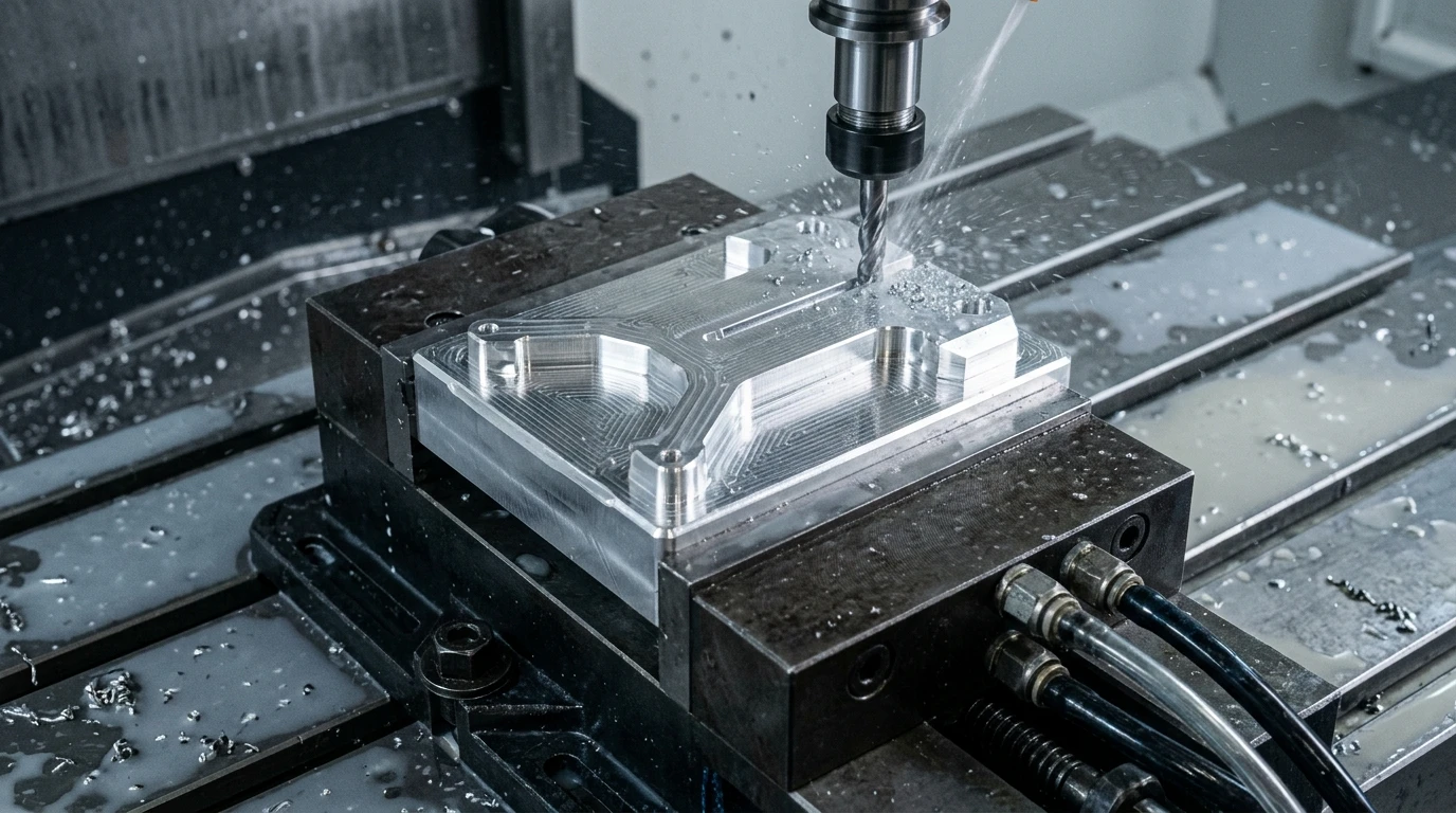
Machining complex parts requires more than just high-power CNC spindles. The cutting path guided by your code dictates total cycle time, cutter life, and part accuracy.
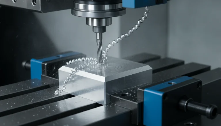
This path is known as the CNC machining toolpath. It directs every movement of the cutter across the raw metal stock.
Consequently, skilled CAM programmers spend hours optimizing toolpaths before cutting metal. In addition, proper toolpath planning stops tool chatter, cuts cycle times, and protects high-value parts.
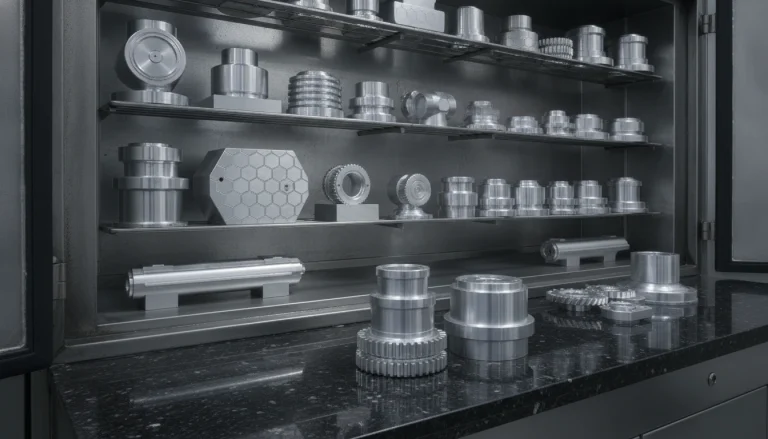
At AS Prototypes, our machinists leverage advanced precision CNC machining services to build tight-tolerance components. In this guide, we compare 2D and 3D paths, adaptive milling rules, and multi-axis strategies.
Understanding 2.5D vs 3D Toolpaths
CNC toolpaths fall into two main families based on cutter movement.
First, 2.5D toolpaths move the cutter along planar boundaries in X and Y with automated Z-level stepdowns, helical ramping, and depth increments. For example, facing, adaptive pocketing, and 2.5D profile milling use these structured multi-depth motions.
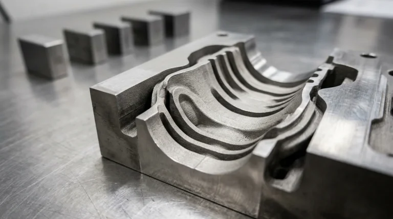
In contrast, 3D toolpaths drive all three axes at the same time. This continuous multi-axis motion is essential for organic shapes, curved molds, and aero surfaces.
Furthermore, modern CAM tools feature adaptive clearing algorithms. Instead of taking full-width heavy slot cuts, adaptive paths maintain a steady tool engagement angle.
| Toolpath Strategy | Cutter Motion | Tool Engagement | Surface Finish (Ra) | Best Application |
|---|---|---|---|---|
| Face Milling | Planar 2D passes | 65% to 75% cutter diameter | 0.8 to 1.6 μm | Squaring stock and creating datum surfaces. |
| Trochoidal Adaptive | Dynamic circular peeling loops | Constant 10% to 15% radial step | Roughing stage | Deep pockets in titanium and hard steels. |
| 3D Scallop & Contour | Simultaneous 3-axis surface tracking | Very light finishing stepover | 0.4 to 0.8 μm | Injection mold cores, cavities, and optics. |
| 5-Axis Simultaneous | Continuous 5-axis swarf and point cut | Optimized lead and tilt angle | 0.2 to 0.4 μm | Turbine blisks, impellers, and bone plates. |
High-Speed Machining and Trochoidal Milling
Traditional roughing methods plunge end mills deep into corners. As a result, cutting forces spike, tools deflect, and cutters frequently snap.
Trochoidal milling solves this problem. It uses smooth spiral motions and shallow radial cuts paired with deep axial passes.
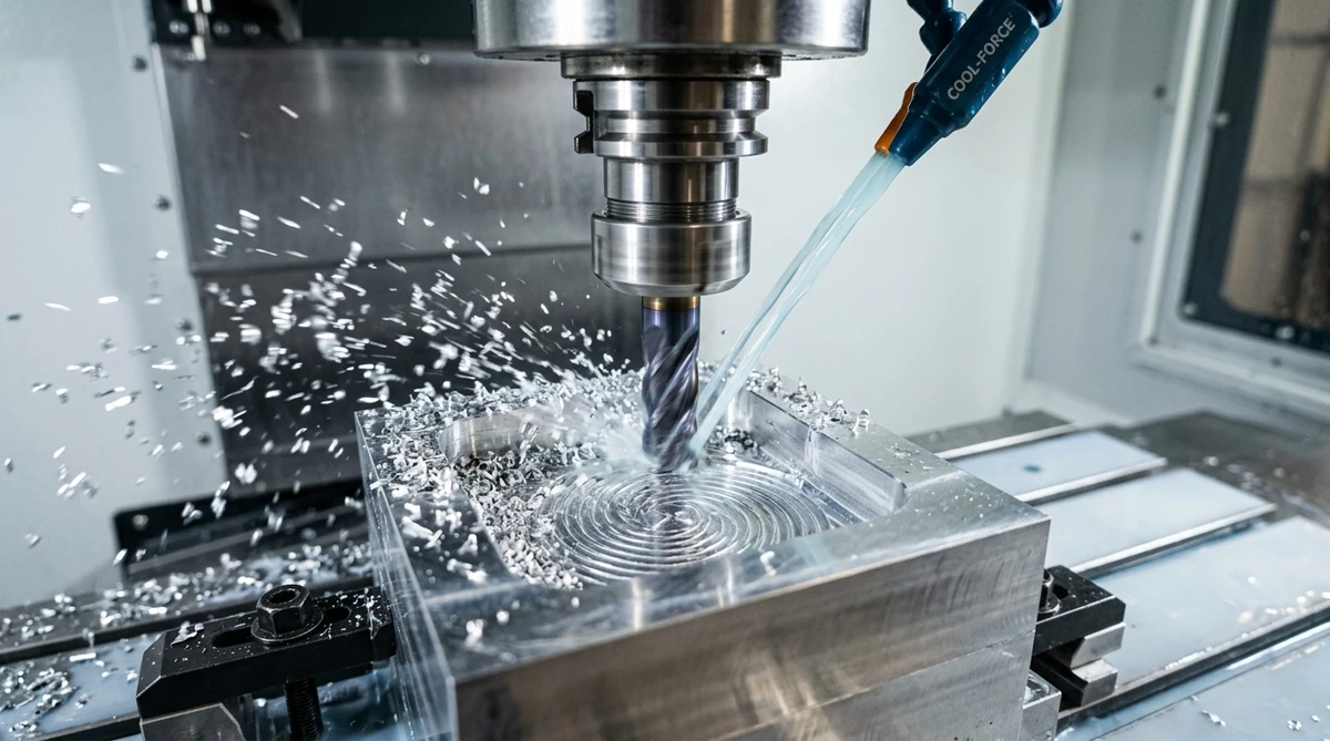
Because the cutting load remains constant, spindle speeds can run much faster. Therefore, roughing cycle times drop by up to 50 percent while tool life triples.
In addition, heat leaves the part inside the flying chips rather than heating the stock. This stops thermal warping on thin-walled aerospace housings.
| Milling Operation | Recommended Tool | Radial Stepover (% Dia) | Axial Depth of Cut | Coolant Strategy |
|---|---|---|---|---|
| Adaptive Roughing | 3-Flute or 4-Flute Rougher | 10% to 15% | 1.5x to 2.5x Tool Diameter | High-pressure blast or flood coolant. |
| Wall Profiling | Multi-Flute Finishing Mill | 0.1 mm to 0.2 mm | Full Wall Height (rigid setups L/D ≤ 2) or Stepped Axial Stepdowns (deep pockets L/D > 3 to prevent cantilever deflection) | Flood coolant to wash chips away. |
| 3D Scallop Finish | Ball-Nose or Bull-Nose Mill | 3% to 8% | 0.05 mm to 0.1 mm | Mist or air blast on hardened tool steel. |
| Deep Hole Drilling | Through-Coolant Carbide Drill | 100% (Full Diameter) | Peck cycle per 2x Diameter | Internal high-pressure through coolant. |
Advanced 5-Axis Multi-Axis Toolpaths
Standard 3-axis mills cannot reach undercut pockets or steep internal corners. Machinists must set up the part multiple times, which introduces datum stack errors.
In comparison, our 5-axis machining centers tilt and rotate the workpiece continuously. As a result, cutters use shorter, stiffer tools that resist chatter.
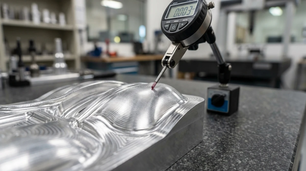
Moreover, 5-axis swarf cutting uses the side of the tool rather than its tip. This produces mirror-like surface finishes across complex aerospace vanes.
Adaptive clearing maintains a constant tool engagement angle. This eliminates cutter shock load, cuts heat buildup, and extends tool life dramatically.
2D paths move along X and Y while Z stays at fixed step depths. In contrast, 3D toolpaths move all three axes together to sculpt curved surfaces.
5-axis toolpaths tilt the cutter so it stays in its sweet cutting zone. This avoids cutting with the zero-speed center tip of ball-nose end mills.
Need Tight-Tolerance Multi-Axis CNC Machining?
AS Prototypes deploys state-of-the-art 3-axis and 5-axis CNC machining centers to produce high-precision parts in aluminum, titanium, and engineering plastics. Upload your CAD models today for expert DFM review and an instant quote.
Upload CAD Files for Instant Quote