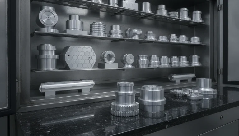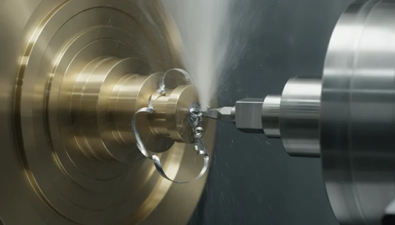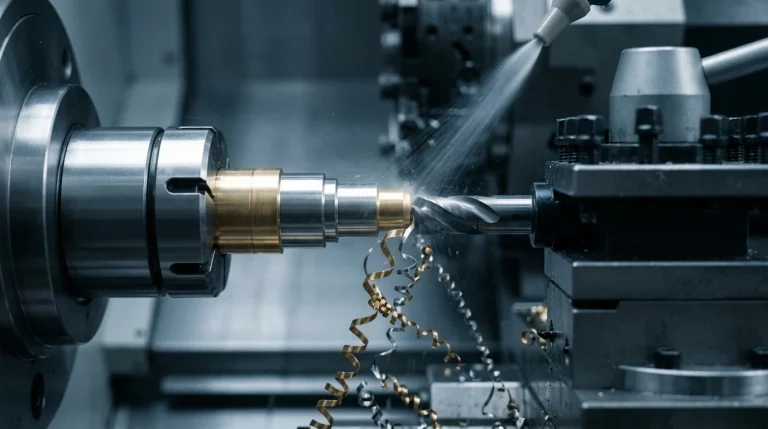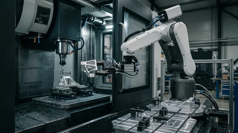
Aluminum alloys—chiefly 6061-T6, 7075-T6, and 2024-T3—form the structural backbone of modern precision prototyping, aerospace airframes, automotive battery housings, and optical electronics. Celebrated for high strength-to-weight ratios, excellent thermal conductivity, and natural corrosion resistance, aluminum is widely regarded by machinists as an “easy-to-cut” material. Yet, in high-volume production and complex prototype milling, treating aluminum like a forgiving metal is a recipe for costly scrap: gummy chip welding, severe tool chatter in deep pockets, catastrophic cutter gumming, and warped thin walls caused by residual thermal stress.
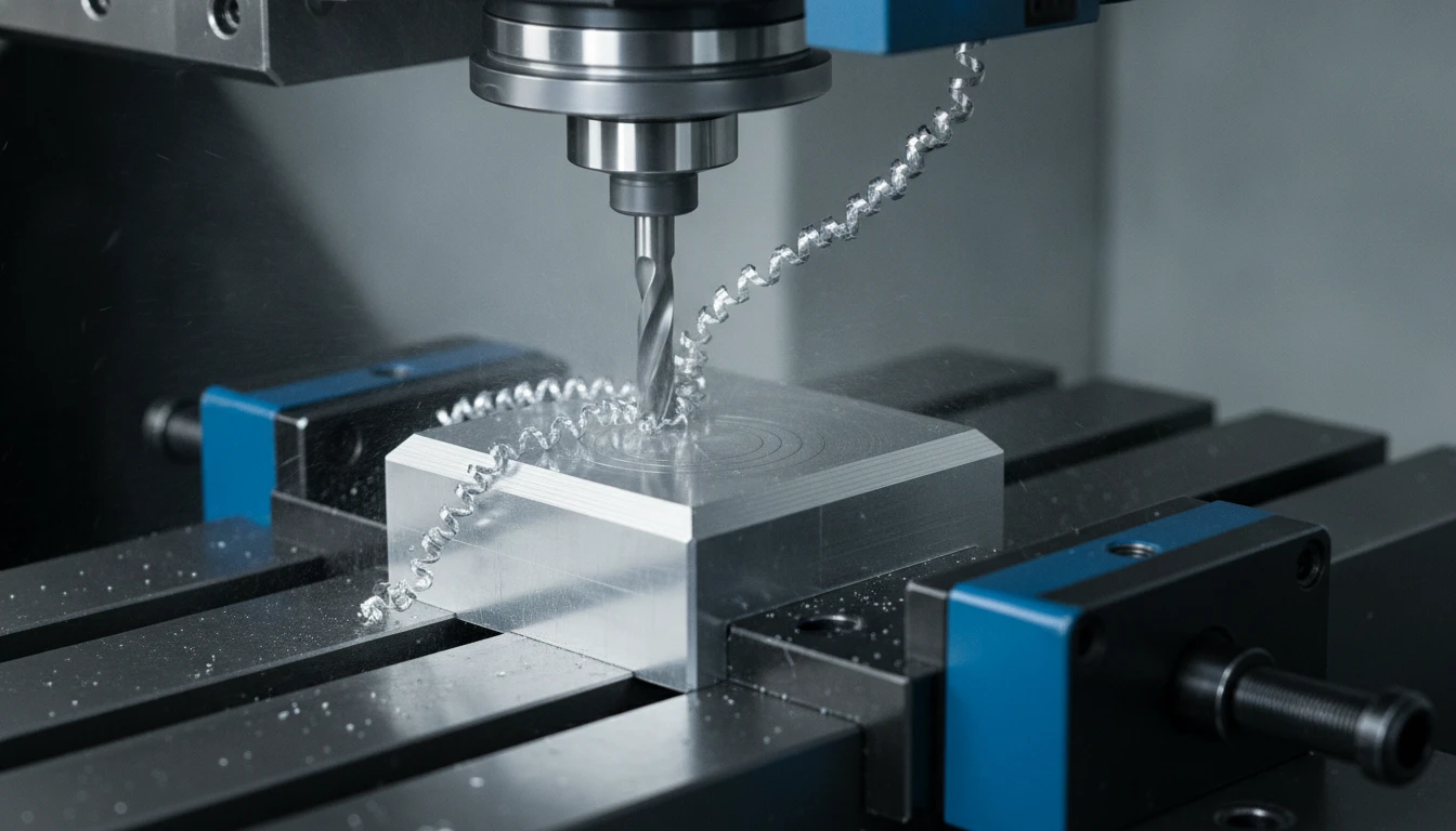
To overcome these challenges and unlock maximum productivity, leading manufacturing facilities deploy High-Speed Machining (HSM). Modern HSM is not merely running an older CNC mill at full throttle; it is an integrated engineering discipline that synthesizes Carl Salomon’s cutting temperature curves, radial chip thinning compensation, constant tool engagement kinematics, and specialized lubricious coatings. Operating at spindle speeds between 15,000 and 24,000+ RPM and cutting velocities exceeding 1,200 m/min, HSM slashes cycle times by up to 60% while achieving sub-micron surface finishes and zero thermal distortion.
In this technical guide, AS Prototypes deconstructs the thermodynamics, toolpath mechanics, cutter geometries, and coolant dynamics required to master high-speed aluminum milling.
The Thermodynamics of HSM: Carl Salomon’s Curve & Heat Evacuation
A persistent misconception among novice machinists is that higher cutting speeds generate runaway heat that destroys carbide cutters. In reality, modern metal-cutting physics proves the exact opposite when operating in the high-speed regime, as first hypothesized by German inventor Carl Salomon.
In conventional low-speed milling (cutting speed $V_c$ between 100 and 300 m/min), cutting temperature rises proportionally with velocity, peaking around 600°C to 800°C. However, once cutting velocity surpasses an alloy’s critical inflection threshold ($V_c \ge 1,000$ to 1,500 m/min in aluminum), an astonishing thermodynamic phenomenon occurs:
- Adiabatic Shear Banding: The plastic shear deformation in the primary shear zone takes place faster than heat can physically conduct into the workpiece or the carbide tool substrate.
- Chip Heat Entrainment: Over 80% to 90% of the total thermal energy generated during the cut is carried away instantaneously inside the plastically sheared, rapidly evacuated solid chips.
- Cold Workpiece Machining: Because the heat leaves with the chip, the temperature of the finished workpiece rarely exceeds 150°C to 200°C (often staying below 80°C in flood-cooled setups). Thermal expansion of the workpiece is virtually eliminated, guaranteeing tight dimensional tolerances (±0.01 mm) and preventing warping on delicate 0.8 mm thin walls.
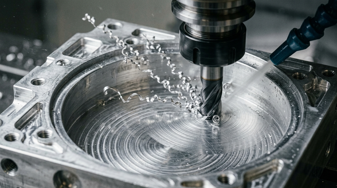
Toolpath Kinematics: Precision CNC Milling & Chip Thinning
1. Constant Tool Engagement Angle (Trochoidal Milling)
In legacy CNC programming, end mills executed traditional linear raster or offset pocket toolpaths. When an end mill plunged into an inside 90° corner, the tool’s angle of engagement ($ heta_e$) spiked instantly from 90° to 180°. This localized shock load quadrupled radial cutting forces, deflected the tool shank, induced loud harmonic chatter, and frequently snapped carbide cutters.
Modern high-speed machining employs Trochoidal Milling (Dynamic / Adaptive Clearing):
- Constant Radial Immersion: By continuously adjusting circular interpolation loops and trochoidal step-overs, the CAM algorithm maintains a strictly constant engagement angle (typically $ heta_e = 30^\circ$ to $45^\circ$).
- Full Axial Depth Engagement: Because radial engagement ($a_e$) is kept small (typically 5% to 15% of tool diameter $D$), the cutter can safely engage at full flute length (axial depth $a_p = 2 imes$ to $3 imes D$).
- Massive Material Removal Rates (MRR): Using the entire flute distributes wear evenly along the cutting edge rather than concentrating it on the tip, pushing MRR beyond 500 to 700 cm³/min on 5-axis machining centers.
2. The Radial Chip Thinning Factor (RCTF)
When the radial depth of cut ($a_e$) drops below 50% of tool diameter ($D$), the actual maximum chip thickness ($h_{max}$) produced at the cutting edge is significantly smaller than the programmed feed per tooth ($f_z$):
h_max = f_z × √(a_e / D)
If an engineer programmes a light finishing pass or dynamic trochoidal stepover ($a_e = 10\% D$) without compensating for chip thinning, the actual chip thickness shrinks to under 0.02 mm. Instead of shearing clean metal, the tool rubs, burnishes the surface, causes severe work-hardening, and welds gummy aluminum to the flank face.
To preserve ideal shearing physics, modern CAM software calculates the Chip Thinning Compensation Feed Rate, boosting programmed linear feed rates by 2.0× to 3.5×. Spindles spinning at 20,000 RPM routinely feed at 8,000 to 15,000 mm/min without compromising edge integrity.
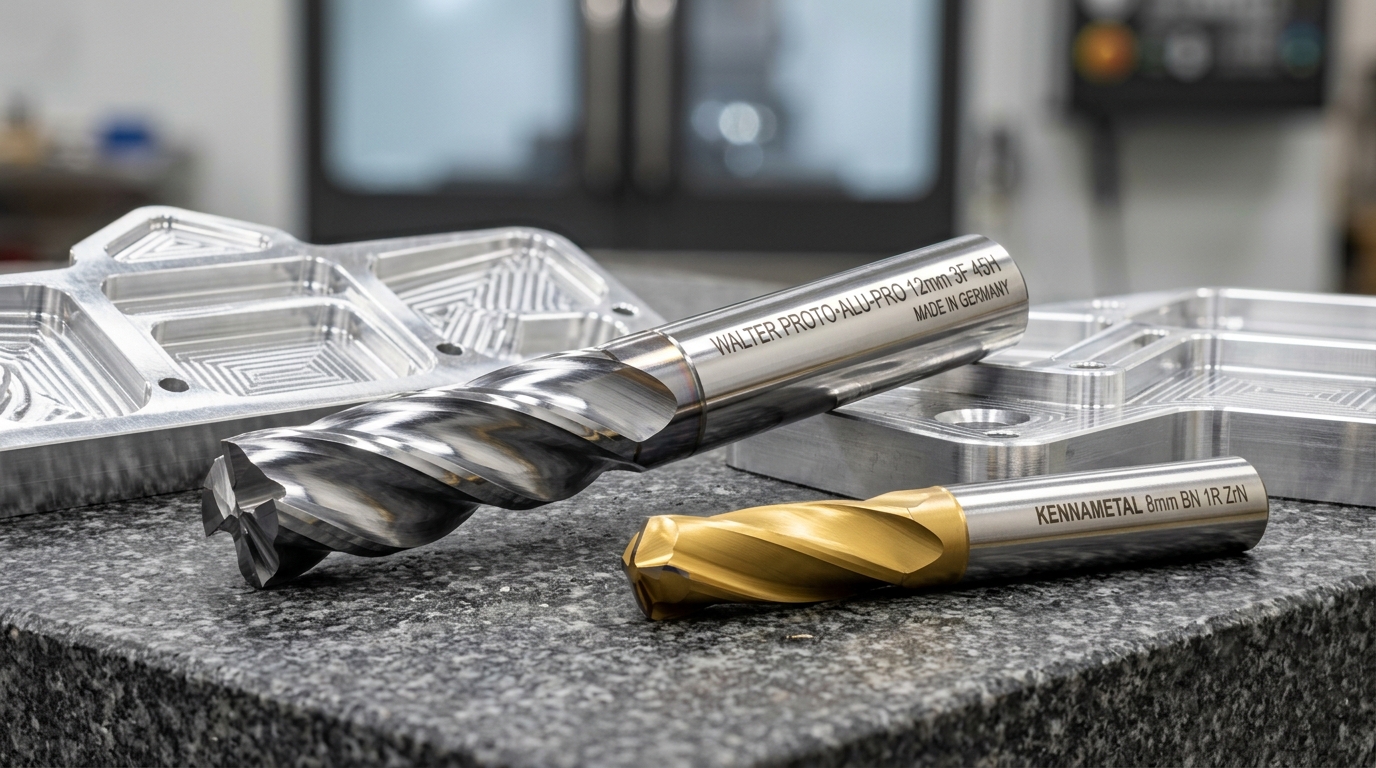
Cutter Geometries & Coatings Engineered for Aluminum
Aluminum is ductile, soft, and chemically prone to galling. Standard 4-flute steel end mills will pack with chips and shatter within seconds. Precision aluminum milling demands tailored tool architecture:
1. 3-Flute vs. 2-Flute Geometry with 45° High Helix
- 2-Flute Cutters: Offer maximum chip flute space for deep slotting and heavy plunging where chip evacuation is paramount.
- 3-Flute Cutters: The ultimate balance for high-speed dynamic milling. Provides 50% more cutting edges per revolution than a 2-flute tool while maintaining generous chip gullets, delivering higher table feed rates and superior harmonic dampening.
- 45° to 55° High Helix: Creates an upward shearing action that ejects chips vertically out of deep pockets while directing cutting forces down into the machine table rather than laterally against thin walls.
2. Mirror-Polished Flutes & Low-Friction Coatings
The primary failure mode in aluminum milling is Built-Up Edge (BUE)—microscopic aluminum particles welding to the cutting face due to extreme localized pressure and frictional heat:
- Mirror-Polished Flutes: Polishing the carbide flute gullets to a mirror finish (Ra ≤ 0.05 μm) reduces surface friction, preventing chips from sticking.
- Zirconium Nitride (ZrN) Coating: A brilliant golden PVD coating with virtually zero chemical affinity to non-ferrous aluminum, maintaining razor sharpness while offering an ultra-low friction coefficient (μ ≈ 0.15).
- Diamond-Like Carbon (DLC) & PCD: For abrasive cast aluminum alloys containing high silicon (e.g., A380 with > 9% Si or AlSi10Mg additive parts), amorphous DLC coatings or brazed Polycrystalline Diamond (PCD) tips resist abrasive tooth rounding, lasting 20× longer than standard carbide.
Coolant Strategies: High-Pressure Flood vs. MQL vs. Air Blast
In high-speed aluminum milling, chip recutting is the silent killer. If an end mill strikes a loose aluminum chip already evacuated from the cut, cutting forces spike, chipping the razor edge and embedding burrs into the finish.
- High-Pressure Through-Spindle Coolant (TSC, 30 to 70 Bar): Injects high-velocity coolant directly through internal tool channels, flushing chips instantly out of deep pockets and drilling blind holes without thermal shock.
- Minimum Quantity Lubrication (MQL): In high-speed 5-axis contouring, MQL atomizes a micro-droplet aerosol of biodegradable vegetable ester oil directly onto the tool-workpiece interface using high-pressure compressed air (6 to 8 bar). The air blast evacuates chips while the oil film eliminates frictional heat.
- Vortex Chilled Air Blast: For dry prototype milling where coolant residue must be avoided (e.g., medical or cleanroom enclosures), vortex tubes deliver compressed air at -20°C, freezing the chip and preventing chip gumming.
Alloy Machinability: 6061-T6 vs. 7075-T6 vs. Cast Aluminum
| Aluminum Alloy | Key Alloying Elements | Machinability Characteristics | Optimal Cutting Speed (Vc) | Tooling & Coating Recommendation |
|---|---|---|---|---|
| Al 6061-T6 | Mg, Si (0.8–1.2%) | Ductile, highly formable; prone to BUE if speed is too low; excellent anodizing response | 800 to 1,500 m/min | 3-flute 45° helix, mirror-polished uncoated carbide or ZrN |
| Al 7075-T651 | Zn (5.1–6.1%), Mg, Cu | High tensile strength (570 MPa); crisp, brittle chip formation; exceptional mirror finish | 1,000 to 2,200 m/min | High-rigidity 3-flute carbide with corner radii, ZrN or TiB2 coating |
| Al 2024-T3 / T4 | Cu (3.8–4.9%), Mg, Mn | Aerospace airframe alloy; short breaking chips; requires corrosion protection post-cut | 900 to 1,800 m/min | 3-flute high-shear carbide, generous high-pressure flood coolant |
| Cast A380 / ADC12 | Si (7.5–9.5%), Cu, Fe | Highly abrasive due to hard silicon precipitates; rapid abrasive flank wear on carbide | 600 to 1,200 m/min | PCD (Polycrystalline Diamond) tipped or thick CVD diamond coated end mills |
Engineering Comparison: Conventional vs. High-Speed Aluminum Milling
| Machining Parameter | Conventional Low-Speed Milling | High-Speed Machining (AS Prototypes) | Engineering & Economic Benefit |
|---|---|---|---|
| Spindle Speed Range | 3,000 to 8,000 RPM | 15,000 to 24,000+ RPM | Triples cutting velocity into the Salomon heat-evacuation zone |
| Axial / Radial Cut Ratio | Shallow step-down (0.1–0.2 D) & wide step-over | Deep axial (1.5–3.0 D) & light radial (5–15% D) | Distributes wear across entire flute length, extending tool life |
| Material Removal Rate (MRR) | 60 to 150 cm³/min | 400 to 750+ cm³/min | Cuts cycle times by 40% to 65% on pocketed aerospace chassis |
| Workpiece Thermal Distortion | Moderate to high (heat conducts into part) | Near zero (85%+ heat leaves in rapidly evacuated solid chips) | Enables deflection-free machining of 0.5 mm thin walls & fins |
| Surface Finish (Ra) | Ra 1.6 to 3.2 μm (tool marks & chatter) | Ra 0.4 to 0.8 μm (Specular luster) | Direct cosmetic finish ready for Type II/III anodizing |
AS Prototypes: Your Partner for Precision CNC Aluminum Machining
Achieving micron-level tolerances and pristine cosmetic finishes in aluminum requires deep mastery of machine kinematics, cutting thermodynamics, and tooling dynamics. At AS Prototypes, our facility is equipped with high-speed 3-axis, 4-axis, and simultaneous 5-axis CNC machining centers running spindle speeds up to 24,000 RPM.
Every aluminum component undergoes comprehensive Design for Manufacturing (DFM) analysis—evaluating wall thickness transitions, corner radius optimization, and stress-relieved billet clamping—to deliver pristine parts on time and on budget.
When radial stepover ae is below 50% of the cutter diameter, the cutting tooth leaves the cut before reaching maximum chip thickness, producing a thinner average chip (hm). Feed per tooth must be accelerated to maintain nominal cutting pressure and prevent rubbing.
Under high surface footage (Vc > 800 m/min), plastic shear occurs faster than heat can conduct into the parent workpiece. Over 85% of cutting thermal energy is carried away inside the ejected solid chips.
Uncoated polished carbide tools with sub-micron grain structures, or specialized DLC (Diamond-Like Carbon) coatings, are preferred. Titanium-based coatings (TiN, AlTiN) must be avoided because aluminum has high chemical affinity for titanium at cutting temperatures, causing severe galling.
Accelerate Your CNC Aluminum Machining Projects
Whether you require a single high-precision aerospace prototype in 7075-T6, complex 5-axis electronic chassis in 6061-T6, or low-volume production batches with high-durability Type II/III anodizing per MIL-A-8625, AS Prototypes provides the high-speed machining excellence your project demands.
Submit Your 3D CAD Files for Instant Aluminum Machining DFM & Quotation →