In mechanical design and precision CNC manufacturing, achieving a permanent, backlash-free mechanical joint without the weight, bulk, or dynamic vulnerability of threaded fasteners, keys, or adhesives is a frequent engineering objective.
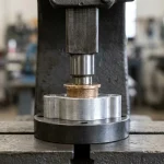
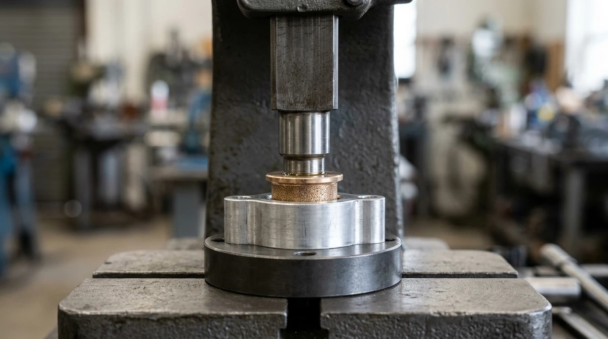
A press fit (also classified as an interference fit or force fit) achieves this by deliberately manufacturing a shaft with an external diameter slightly larger than the mating bore diameter of the hub or housing. In precision manufacturing, mastering press fit tolerance ensures repeatable dimensional stability and predictable production scaling.
When pressed together under controlled axial tonnage or differential thermal assembly (shrink fitting), the elastic deformation of the mating metal surfaces generates high normal contact pressure across the mating interface. This contact pressure produces substantial frictional resistance, enabling the joint to transmit high torsional moments, endure axial thrust, and maintain strict coaxial runout under severe reversing dynamic loads.
However, calculating and executing the correct press fit tolerance is a critical engineering challenge. If the interference is insufficient, dynamic vibration or thermal expansion differentials can cause micro-slippage, fretting fatigue, or joint walk-out. Conversely, excessive interference generates hoop stresses that exceed the material’s yield strength (Sy), precipitating permanent hub distortion, stress-corrosion cracking, bearing raceway pre-loading, or catastrophic brittle burst during installation.
At AS Prototypes, we produce mission-critical rotating shafts, precision gear hubs, and bearing housings held to micron-level tolerances. This engineering guide details the ISO 286 limit and fit system, Lamé thick-walled cylinder equations for contact pressure, insertion force calculations, thermal shrink-fit mechanics, and shop-floor Design for Manufacturing (DFM) rules.
- Core Focus & DFM Scope: Actionable shop-floor engineering guidelines for press fit tolerance, covering material selection, geometric tolerancing, and defect prevention.
- Achievable Tolerance Envelope: General features hold ISO 2768-mK; critical bearing bores, dowel pins, and mating datums hold ±0.010 to ±0.020 mm (±0.0004″ to ±0.0008″), with Wire EDM/grinding to ±0.005 mm (±0.0002″).
- Machining & Surface Integrity: High-speed 3-axis and 4-axis VMCs (with simultaneous 5-axis for complex contours) delivering as-machined Ra 0.8 µm (32 µin) to Ra 0.4 µm (16 µin) per ASME B46.1.
- Metrology & Process Control: On-machine spindle probing paired with 20°C (68°F) climate-controlled Zeiss CMM coordinate verification and calibrated Go/No-Go plug/ring gauges.
- Ex-Factory Turnaround: 4 to 8 business days for as-machined rapid prototypes; 7 to 12 business days for anodized, plated, or multi-operation production runs (excluding 3–5 days air transit).
1. The Fundamentals of Press Fits: Clearance, Transition, and Interference
To establish the correct dimensional envelope on engineering drawings, international standards—principally ISO 286 and ANSI B4.1—categorize cylindrical fits into three fundamental classes based on the relative positioning of the tolerance zones of the mating hole and shaft:
- Clearance Fit: The lower limit of the hole is always greater than or equal to the upper limit of the shaft (Dhole ≥ Dshaft). There is always positive clearance, allowing free relative motion (such as rotating journal bearings or linear guide bushings, e.g., H7/g6, H7/f7).
- Transition Fit: The tolerance zones of the hole and shaft overlap. Depending on the actual manufactured dimensions within tolerance, the assembly may exhibit a slight clearance or a slight interference (e.g., H7/k6, H7/m6). These fits are employed for precise locational alignment where components must be assembled or disassembled easily with a hand mallet or light arbor press without structural deformation.
- Interference (Press) Fit: The upper limit of the hole is always smaller than the lower limit of the shaft (Dshaft > Dhole). Positive material overlap exists across the entire tolerance band. Assembly requires substantial mechanical force, hydraulic pressing, or thermal differential expansion.
2. Hole-Basis vs. Shaft-Basis Tolerancing Systems
When specifying interference tolerances on 2D technical drawings, manufacturing engineers choose between two international reference frameworks:
The Hole-Basis System (Standard Practice)
In the hole-basis system, the basic nominal diameter is assigned to the hole, and the hole’s lower deviation is fixed at zero, denoted by the uppercase letter H (e.g., H7, H8). The desired fit (clearance, transition, or interference) is achieved entirely by varying the shaft’s external diameter tolerance zone, designated by lowercase letters (e.g., g6 for clearance, k6 for transition, p6/s6/u6 for interference).
Why Hole-Basis is the Global Standard: Internal bores are constrained by standard cutting tool diameters. Producing an H7 bore utilizes standard reamers, precision boring heads, plug gauges, and standard honing mandrels. Varying the external shaft diameter via CNC turning, Swiss screw machining, or cylindrical centerless grinding is vastly more adaptable and economical on modern production equipment.
The Shaft-Basis System
In the shaft-basis system, the upper deviation of the shaft is fixed at zero, designated by the lowercase letter h (e.g., h6, h7), while the hole tolerance zone is varied using uppercase letters. This system is primarily applied when multiple mating components with different fit requirements (e.g., a rotating pulley, a stationary bearing, and a retaining collar) must mount onto a single continuous length of precision ground, pre-drawn cold-finished shafting.
3. ISO 286 Press Fit Classifications and Selection Chart
The ISO 286 system provides standardized letter-number combinations designating the magnitude of interference and the precision grade of manufacturing. Below is an engineering reference table detailing standard ISO hole-basis interference fits commonly machined and assembled at AS Prototypes:
| ISO Fit Class | Classification | Nominal Ø Range | H7 Hole Tol (μ m) | Shaft Tol (μ m) | Interference (μ m) | Assembly Technique | Typical Engineering Applications |
|---|---|---|---|---|---|---|---|
| H7 / k6 | True Transition / Locational | 18 – 30 mm | 0 to +21 | +2 to +15 | -19 clr to +15 int | Lead mallet / light arbor press | Precision dowel pins, ball bearing inner rings subject to light loads. |
| H7 / m6 | Transition / Snug Drive | 18 – 30 mm | 0 to +21 | +8 to +21 | -13 clr to +21 int | Arbor press with alignment jig | Gearbox output shafts, replaceable bronze guide bushings, demountable sprockets. |
| H7 / p6 | Light Press / Locational Interference | 18 – 30 mm | 0 to +21 | +22 to +35 | +1 to +35 int | Manual or hydraulic arbor press | Permanent bronze journal bushings, keyed drive shafts, non-slipping pulleys. |
| H7 / r6 | Medium Drive Fit | 18 – 30 mm | 0 to +21 | +28 to +41 | +7 to +41 int | Hydraulic press with anti-seize | Semi-permanent couplings, cast iron valve guides, heavy-duty industrial sprockets. |
| H7 / s6 | Heavy Force Fit | 18 – 30 mm | 0 to +21 | +35 to +48 | +14 to +48 int | Heavy hydraulic press / thermal assist | Permanent press-fit gear rims on steel hubs, locomotive axle assemblies, motor armatures. |
| H7 / u6 | Shrink / Severe Force Fit | 18 – 30 mm | 0 to +21 | +48 to +61 | +27 to +61 int | Induction heat hub + cryogenic shaft | Extreme torque transmission without keys, turbine rotor discs, heavy forged machinery. |
4. Mathematical Formulation: Contact Pressure, Stresses & Assembly Force
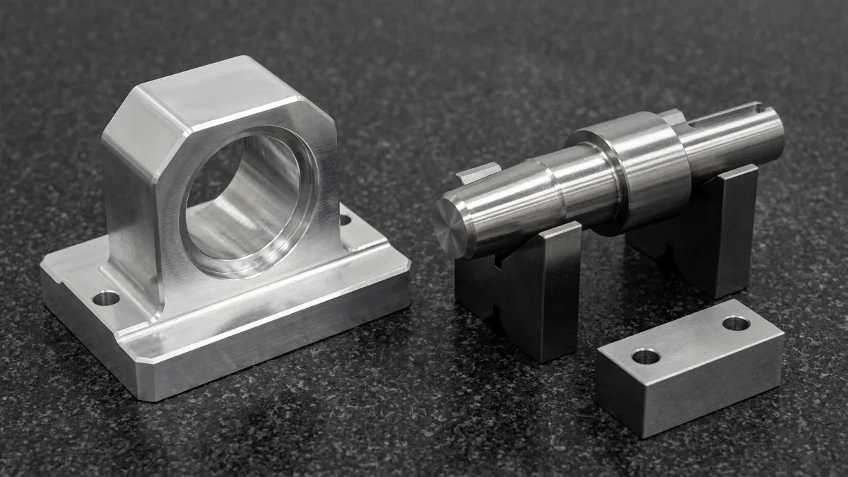
Calculating a press fit requires quantitative mechanics to guarantee that the minimum interference transmits the required torque without slipping, while the maximum interference does not cause permanent plastic yield in either component.
Step 1: Diametral Interference Boundaries
The total diametral interference (δ) is defined by the difference between the actual shaft diameter (Ds) and the actual hole diameter (Dh):
δmin = Ds,min – Dh,max
Step 2: Effective Interference and Surface Finish Correction
When two machined components are forced together, the microscopic surface asperities (roughness peaks) are flattened, sheared, or plastically burnished. Consequently, the effective interference (δeff) that generates elastic contact pressure is smaller than the measured pre-assembly dimensional interference:
Engineering Note: On rough-turned surfaces (Ra = 3.2 μ m), asperity flattening can eliminate up to 7.7 μ m of calculated interference. This is why AS Prototypes enforces precision cylindrical grinding or diamond burnishing (Ra ≤ 0.4 μ m) on all press-fit journals.
Step 3: Interface Contact Pressure via Lamé Thick-Walled Cylinder Theory
Assuming both the outer hub (subscript h) and the inner shaft (subscript s) behave elastically, the interface contact pressure (p) across the nominal mating diameter (D) is derived from Lamé’s equations for thick-walled cylinders:
Where:
- D = Nominal interface diameter (mm)
- Do = Outer diameter of the hub or housing (mm)
- Di = Inner bore diameter of a hollow shaft (mm); for a solid shaft, Di = 0, simplifying the shaft term to ((1 – νs)) / (Es)
- Eh, Es = Modulus of Elasticity for hub and shaft materials (MPa or N/mm2)
- νh, νs = Poisson’s ratio of hub and shaft materials
Step 4: Stress Distribution and von Mises Yield Verification
Under internal pressure p, the hub experiences maximum tensile circumferential (hoop) stress (σt) and compressive radial stress (σr) at its innermost bore (r = D / 2):
σr,max = -p
Using the von Mises failure criterion for ductile materials under plane stress, the equivalent stress (σv) must remain safely below the material’s yield strength (Sy) with an adequate safety factor (SF ≥ 1.5):
Step 5: Axial Press-In Force & Transmissible Torque
The maximum axial force (Fpress) required to assemble the components mechanically at room temperature is given by:
Where L is the axial length of the joint engagement and μ is the coefficient of static friction during pressing (μ ≈ 0.12 – 0.15 with extreme-pressure assembly lubricant; μ ≈ 0.18 – 0.25 dry clean steel-on-steel).
Similarly, the maximum torque (Ttrans) the joint can transmit before slipping circumferentially is:
5. Thermal Shrink Fitting vs. Mechanical Cold Pressing
For heavy interference fits (such as ISO s6 or u6), mechanical pressing at ambient temperature demands enormous tonnage and introduces severe risks of galling, metal pickup, and bore scuffing. In these scenarios, differential thermal expansion (shrink fitting) is the industry gold standard.
Thermal Expansion Mechanics
The change in diameter (Δ D) of a component when subjected to a temperature differential (Δ T) is governed by its linear coefficient of thermal expansion (α):
Where cassembly is the temporary clearance required during insertion (typically 0.015 – 0.030 mm) to prevent freezing or binding mid-stroke.
Shop Floor Thermal Methods
- Heating the Outer Hub: Controlled induction heating (typically to 150°C – 250°C) evenly expands the housing bore without altering the core metallurgical microstructure or drawing back quenched temper. Open oxy-acetylene torch heating must be strictly prohibited due to local overheating, localized annealing, and metallurgical warping.
- Cryogenic Chilling of the Inner Shaft: Immersing the shaft in dry ice (-78.5°C) or liquid nitrogen (-196°C) contracts the shaft diameter. Cryogenic cooling eliminates oxidation scale and thermal discoloration on polished surfaces.
- Combined Dual Thermal Method: Heating the housing moderately (+120°C) while cryogenically chilling the shaft (-196°C) provides massive clearance margins for large-diameter marine, mining, and aerospace assemblies.
6. Metrology and Quality Assurance for Tight Tolerance Press Fits
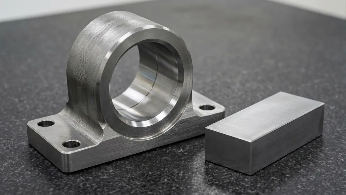
When working with interference tolerances where the total process window is frequently under 15 μ m (0.015 mm), standard shop-floor measurement practices are insufficient. AS Prototypes integrates a rigorous metrology validation protocol:
1. Temperature-Controlled Environment (20°C ± 0.5°C)
Steel expands by approximately 11.5 μ m / (m · °C), while aluminum expands by 23 μ m / (m · °C). A 10°C temperature variance during inspection will distort a 50 mm aluminum bore measurement by more than 11 μ m—exceeding the entire H7 tolerance band! All critical press-fit components undergo a minimum 4-hour thermal soaking period in our ISO Class 7 metrology laboratory before final inspection.
2. Traceable Bore & Shaft Metrology Tools
- Pneumatic Air Gages: Non-contact pneumatic gaging measures internal bores with sub-micron repeatability (0.1 μ m) while detecting geometric taper, lobing, and out-of-roundness simultaneously.
- Three-Point Internal Micrometers: Calibrated directly against verified Class XX master setting rings before every measurement batch.
- Coordinate Measuring Machines (CMM): High-precision scanning CMMs verify true cylindrical form, concentricity, and perpendicularity to adjacent datum faces.
7. Design for Manufacturing (DFM) Rules for Reliable Press Fits
Decades of precision machining and mechanical assembly have produced key DFM principles that eliminate assembly line failures:
Rule 1: Always Specify Lead-In Chamfers
Square mating edges are the primary cause of galling, metal shaving, and cocking. Always design a 15° to 20° shallow lead chamfer on the leading end of the shaft with an axial length of 1.5 – 3.0 mm, accompanied by a generous entry radius on the housing bore mouth.
Rule 2: Maintain Optimal Length-to-Diameter Ratios (L/D)
Keep the engagement ratio between 0.8 ≤ L/D ≤ 1.5. An L/D < 0.5 allows the shaft to wobble or tilt out of square during initial insertion. An L/D > 2.0 creates excessive insertion force, leading to stick-slip galling before full axial engagement is achieved.
Rule 3: Incorporate Relief Bleed Grooves on Blind Bores
Press-fitting a solid shaft or bushing into a blind hole compresses the trapped air inside the cavity. Under high-speed hydraulic pressing, this air pressure acts as a pneumatic spring, resisting full seating or pushing the bushing back out once the press ram retracts. Provide a small axial air bleed flat (0.2 mm deep) or a cross-drilled vent hole in the housing.
Rule 4: Account for Dissimilar Metal Thermal Expansion
When pressing a steel bearing sleeve into an aluminum housing, operating temperature changes dramatically alter the fit. At elevated temperatures (+100°C), the aluminum housing expands more than twice as fast as the steel sleeve, potentially causing a loss of interference fit. In cryogenic environments, the housing shrinks faster, exponentially elevating contact pressure and potentially yielding the housing. Calculations must be verified at operating temperature extremes.
Shop-Floor Cost-Tolerance Trade-Offs & When NOT to Over-Specify
When releasing production drawings for press fit tolerance, applying blanket ±0.005 to ±0.010 mm (±0.0002″ to ±0.0004″) tolerances across non-mating clearance features increases machining cycle time by 2.0× to 3.5× without improving assembly performance. Our DFM engineers recommend specifying ISO 2768-mK on general structural walls while isolating tight GD&T callouts strictly to functional bearing bores, dowel pins, and sealing interfaces.
In our Shenzhen facility, prismatic 3-axis and 4-axis vertical machining centers (VMCs) with contoured soft jaws handle 80%+ of structural setups with maximum rigidity and cost efficiency, reserving simultaneous 5-axis contouring strictly for compound-angle ports and organic impellers. Every batch undergoes climate-controlled 20°C (68°F) Zeiss CMM verification prior to ex-factory release (4 to 8 business days for raw prototypes; 7 to 12 business days with MIL-A-8625 anodizing or ASTM A967 passivation).
🔗 Related CNC DFM & Metrology Engineering Guides:
To further optimize cycle time and dimensional stability in press fit tolerance, combine proper internal corner relief with datum-based coordinate inspection. Consult our shop-floor engineering guides on Maintaining Dimensional Stability in Thin-Wall Machining, Eliminating Sharp Internal Corners & Tool Deflection, and Precision CMM Metrology & GD&T Verification.
Frequently Asked Questions (FAQs)
What is the difference between a transition fit and an interference fit?
A transition fit has overlapping tolerance zones, meaning the assembled joint may result in either a slight clearance or a slight interference depending on the manufactured sizes. It is intended for precision location where parts can be easily assembled and disassembled without damage. An interference (press) fit always guarantees that the shaft is larger than the bore, creating a permanent, rigid joint that requires substantial force or thermal assistance to assemble.
How does surface finish affect the performance of a press fit?
Surface roughness has a direct effect on effective interference. During pressing, microscopic surface peaks (asperities) are crushed and flattened. On rough surfaces (Ra > 1.6 μ m), up to 60% of calculated interference can be lost due to asperity burnishing, drastically reducing holding torque. AS Prototypes applies precision grinding or micro-finishing (Ra ≤ 0.4 μ m) to ensure that measured interference accurately translates into elastic clamping pressure.
Why is extreme-pressure (EP) lubricant recommended during mechanical pressing?
Direct metal-to-metal sliding under intense contact pressure can cause localized microwelding, leading to severe galling, scratching, and seizure. Applying high-performance assembly paste containing molybdenum disulfide (MoS2) or anti-seize compound provides a durable boundary film that reduces friction, prevents surface tearing, and ensures smooth, progressive seating.
Engineered Tolerances for Flawless Mechanical Fits
Whether your mechanical design requires precision ISO H7/p6 bronze bushing assemblies, high-torque H7/u6 shrink fits, or custom tight-tolerance CNC turned shafts, AS Prototypes provides micron-level CNC machining, wire EDM, precision grinding, and full CMM inspection reports.
Upload Your CAD Drawings for DFM ReviewAll critical geometric tolerances—including true position, runout, perpendicularity, and profile of a surface—are verified in our climate-controlled inspection laboratory utilizing calibrated multi-axis High-precision coordinate measuring machines (CMM) and digital optical profilometers.
Unless otherwise specified on customer CAD drawings, precision CNC metal components are machined to tight ±0.010 mm to ±0.020 mm (±0.0004″ to ±0.0008″) precision on critical features (ISO 2768-mK general), and engineering plastics follow ISO 2768-mK.
Every production batch includes full First Article Inspection (FAI) dimensional reports, calibrated coordinate metrology data sheets, and traceable Mill Test Reports (MTR) verifying raw alloy chemical and mechanical properties.