

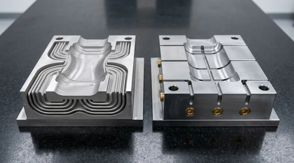
- Thermal Bottleneck: Part cooling accounts for 60% to 75% of the total injection molding cycle time. Traditional gun-drilled channels create severe thermal gradients across complex 3D profiles, whereas conformal circuits achieve uniform heat extraction.
- Cycle Time Compression: Implementing conformal cooling reduces cooling phase duration by 20% to 50%, delivering a net 15% to 35% cycle time reduction across high-volume automotive connectors, electronic housings, and deep-draw containers.
- Thermal Uniformity & Warpage: Conformal channels maintain an equidistant 1.5d to 2.0d boundary from the molding surface, compressing mold surface temperature variation (ΔT) from ±15°C–25°C down to ±1.5°C–2.0°C and eliminating differential shrinkage (ΔS_v).
- Additive Tooling Metallurgy: Laser Powder Bed Fusion (LPBF / DMLS) utilizes 1.2709 (Maraging Steel 300 / MS1) powder, heat-treated via 490°C precipitation aging to reach 50–54 HRC with tensile yield strength exceeding 1,900 MPa.
- Economic Crossover: Conventional tooling remains the cost-effective benchmark for low-volume production (<10,000 parts) and shallow parts; conformal cooling yields decisive ROI on high-volume production (>50,000 parts) where press-hour savings far outweigh initial additive insert fabrication costs.
- Thermodynamics & Transient Heat Transfer in Injection Mold Tooling
- Conventional Cooling: Kinematics, Baffles, Bubblers & Thermal Dead Zones
- Conformal Cooling Architecture & DMLS Additive Metallurgy (1.2709 Maraging Steel)
- Fluid Dynamics & CFD Rules: Turbulent Flow (Re > 10,000) & Self-Supporting Geometries
- Warpage Elimination, Differential Shrinkage & Polymer Crystallinity
- Engineering Data Matrices: Performance, Tooling Alloys & DfAM Parameters
- Post-Processing, CNC Finish Machining & Zeiss CMM Metrology
- Total Cost of Ownership (TCO) & Machine-Hour Economic Break-Even
- Coolant Filtration, Anti-Scaling & Closed-Loop Chiller Maintenance
- Frequently Asked Questions (FAQ)
In high-precision manufacturing, thermal management within the mold tool represents the single greatest lever governing production throughput, part dimensional stability, and unit manufacturing economics. In every commercial injection molding cycle, molten thermoplastic enters the cavity at temperatures ranging from 190°C to over 380°C under pressures exceeding 60 to 180 MPa. Before the tool can open and the ejector pins can advance without causing permanent structural deformation, the component must solidify below its heat deflection temperature (HDT) throughout its thickest nominal cross-section.
Consequently, the cooling phase systematically consumes between 60% and 75% of the total injection molding cycle time. When evaluating conformal cooling vs conventional cooling, tooling engineers are not simply choosing between additive and subtractive toolmaking routes; they are fundamentally choosing between non-uniform, geometrically restricted heat conduction and homogeneous, 3D contour-aligned thermodynamic equilibrium.
At AS Prototypes, our in-house precision injection molding and tooling engineering team couples transient finite-element Moldflow analysis with industrial Direct Metal Laser Sintering (DMLS). By manufacturing 1.2709 maraging tool steel cavity and core inserts with optimized internal fluid circuits, we help medical, automotive, and industrial hardware innovators eliminate intractable warpage and compress mold cycle times by 20% to 50%.
1. Thermodynamics & Transient Heat Transfer in Injection Mold Tooling
To understand why cooling geometry dictates injection molding economics, tooling engineers must examine the underlying thermodynamic laws governing polymer solidification. Thermoplastics are notorious thermal insulators. While mold steels exhibit thermal conductivities (k_steel) between 25 and 35 W/(m·K) and copper beryllium alloys reach 100 to 130 W/(m·K), engineering thermoplastics display thermal conductivities (k_polymer) of merely 0.12 to 0.30 W/(m·K)—nearly two orders of magnitude lower than the surrounding steel.
Heat dissipation through the part wall thickness is governed by Fourier’s law of one-dimensional transient conduction through an isotropic medium:
Here, α denotes the thermal diffusivity of the polymer (α = k / (ρ · C_p)), combining thermal conductivity (k), density (ρ), and specific heat capacity (C_p). Under standard one-dimensional assumptions for a flat plate of nominal thickness h_wall, solving the Fourier heat equation yields the classical analytical expression for the required cooling time (t_cool):
This governing equation highlights two critical physical realities:
- The Square-Law Thickness Penalty: Cooling time scales quadratically with part wall thickness (t_cool ∝ h_wall²). Doubling local wall thickness from 1.5 mm to 3.0 mm quadruples the required cooling duration. If a heavy boss or structural rib creates an isolated mass concentration, the entire press cycle must wait for that single hot spot to solidify.
- The Mold Surface Temperature Driver: The logarithmic term demonstrates that heat extraction efficiency is governed by the thermal gradient between the molten core (T_melt), the mold wall boundary (T_mold), and the safe ejection threshold (T_eject). If mold surface temperature spikes locally due to restricted fluid access, heat extraction collapses exponentially.
In conventional tooling, the steel wall distance between the coolant and the molding surface fluctuates dramatically across the part. Conformal cooling resolves this physical constraint by placing fluid circuits at a mathematically constant distance along every contour, establishing a balanced, isothermal heat flux vector across both core and cavity halves.
2. Conventional Cooling: Kinematics, Baffles, Bubblers & Thermal Dead Zones
Conventional injection mold cooling channels are manufactured using subtractive machining—specifically deep-hole gun drilling and CNC drilling. Gun drilling operates strictly along linear Cartesian vectors (X, Y, Z axes). While gun drilling is exceptionally efficient for machining straight, intersecting waterlines across flat mold plates, it is physically incapable of steering around 3D organic contours, sweeping freeform surfaces, or projecting deep into intricate core features.
To provide cooling to raised cores, deep ribs, and tall shut-offs, toolmakers have historically relied on three mechanical workarounds:
- Baffles: A drilled blind hole features a flat brass or stainless steel blade pressed down the center. Coolant flows up one side of the divider, crosses over the top blade tip, and returns down the opposing side.
- Bubblers: A central brass or stainless tube is threaded into the base of a blind drilled channel. Fluid pumps upward through the inner tube, exits at the crown, and cascades downward through the annular space between the tube outer diameter and the drilled hole.
- Thermal Pins / Heat Pipes: Sealed copper cylinders containing a wick structure and a two-phase working fluid (such as deionized water or acetone under partial vacuum) transfer heat via continuous capillary evaporation and condensation cycles into a remote waterline.
While these legacy methods remain functional for basic geometric profiles, they suffer from fundamental thermodynamic and hydraulic failure mechanisms that degrade mold performance over time:
Prior to reviewing detailed section cutaways, examining the physical geometry of conventional gun-drilled channels illustrates why stagnant boundary layers and thermal bottlenecks form in complex tooling. When gun drills intersect at sharp 90° right angles, sharp stagnation zones starve outer walls of fresh coolant flow, creating severe local hot spots.
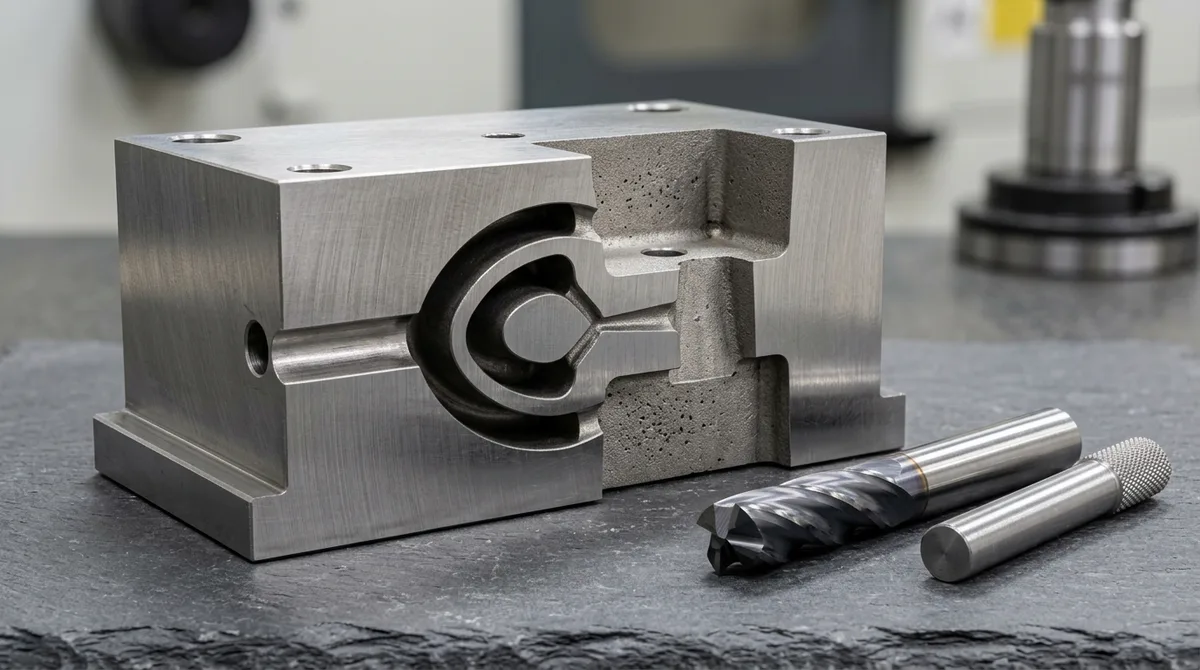
As illustrated in the cutaway tooling insert above, linear drilled circuits force coolant through sharp 90-degree junctions and abrupt expansions. This introduces three catastrophic thermal failure modes:
- Stagnant Flow Zones & Laminar Boundary Layers: Fluid velocities collapse at baffle crossover points and bubbler crowns. When flow velocity drops below the critical threshold, the fluid transitions from turbulent to laminar flow (Reynolds number Re < 2,300). A stagnant fluid boundary layer acts as an insulating blanket, dropping the convective heat transfer coefficient (h) from over 10,000 W/(m²·K) down to less than 1,200 W/(m²·K).
- Mineral Scale Accumulation & Fouling Crusts: Low-velocity dead zones promote the rapid precipitation of calcium carbonate (CaCO_3), rust scale, and biological slime from the chilled water loop. Mineral scale has an abysmal thermal conductivity of 0.5 to 1.5 W/(m·K). A microscopic 0.2 mm scale layer introduces thermal resistance equivalent to adding over 10 mm of solid tool steel between the channel and the part.
- Severe Core vs. Cavity Thermal Imbalance: In typical box-like or cup-shaped geometries, the external cavity plate easily accommodates multiple intersecting waterlines, while the interior core block is crowded with ejector pins, lifter blades, and stripper mechanisms. The core runs 20°C to 50°C hotter than the cavity. This asymmetrical heat extraction drives severe differential shrinkage (ΔS_v), warping sidewalls inward and generating high internal residual stresses.
3. Conformal Cooling Architecture & DMLS Additive Metallurgy (1.2709 Maraging Steel)
Conformal cooling fundamentally redefines mold thermal management by liberating fluid line geometry from Cartesian drill vectors. By utilizing Laser Powder Bed Fusion (LPBF)—commonly referred to in industrial tooling as Direct Metal Laser Sintering (DMLS)—internal cooling passages can follow organic, freeform 3D trajectories that snake uniformly beneath complex contoured cavities, weave around ejector pin sleeves, and penetrate deep into narrow standing ribs.
A direct side-by-side comparison of physical mold tooling highlights the profound architectural divergence between subtractive and additive cooling designs. Where conventional machining relies on straight drilled bores sealed with threaded brass pipe plugs, additive manufacturing integrates smooth, curvilinear internal passages directly within the crystalline matrix of the tool steel.
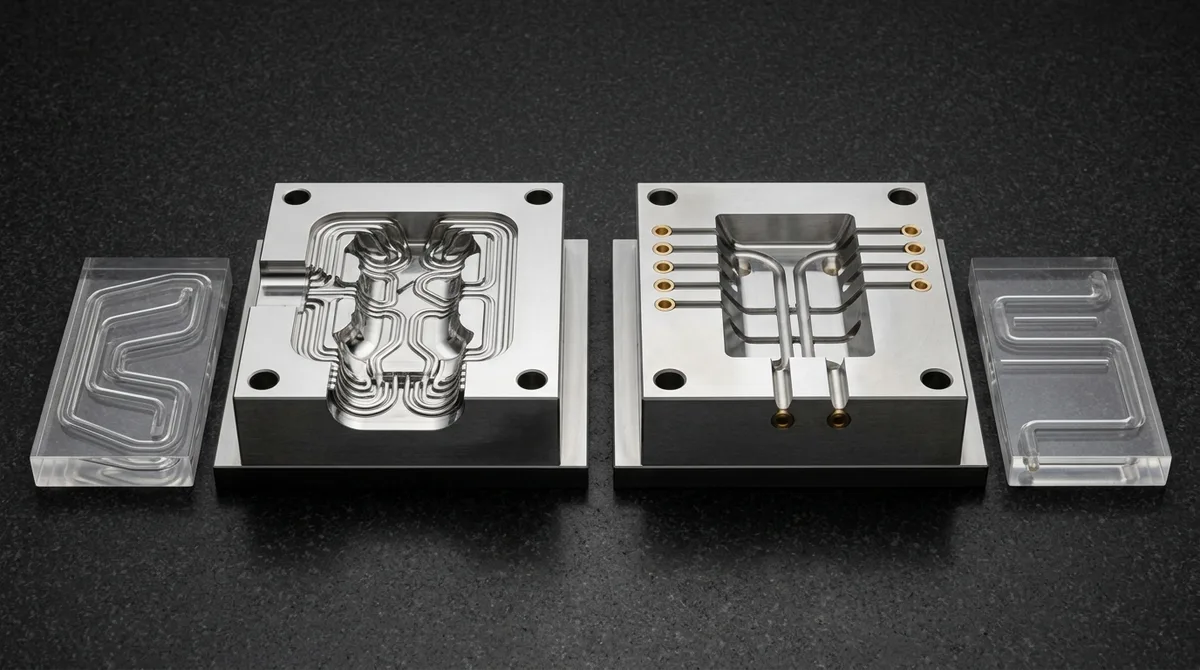
Manufacturing production-grade injection mold inserts via DMLS requires rigorous metallurgical control. Mold inserts endure cyclic clamping pressures exceeding 50 to 200 metric tons, abrasive polymer melt friction, and intense thermal shock cycles repeated hundreds of thousands of times. Standard rapid prototyping materials are utterly inadequate for this operating environment.
The global industrial benchmark alloy for DMLS conformal mold inserts is 1.2709 Maraging Steel (also designated as Maraging 300, 18Ni-300, or EOS MS1). Its unique chemical formulation and precipitation hardening mechanism provide the ideal balance of printability, crack resistance, thermal conductivity, and mechanical fatigue endurance:
- Chemical Composition: Fe balance, 17.0–19.0% Nickel, 8.5–9.5% Cobalt, 4.5–5.2% Molybdenum, 0.6–0.8% Titanium, and crucially, less than 0.03% Carbon.
- Low Carbon Martensite: Unlike conventional carbon tool steels (such as AISI H13 or D2) which form extremely brittle, high-stress martensite upon rapid laser solidification, 1.2709 forms a relatively ductile, low-carbon nickel-iron martensite. This prevents micro-cracking and delamination across complex internal overhangs during laser melting.
- Precipitation Hardening Heat Treatment: As-printed DMLS 1.2709 displays a moderate hardness of 33 to 37 HRC and yield strength around 1,100 MPa, allowing straightforward EDM wire-cutting and initial rough CNC machining. Inserts are subsequently placed in an inert vacuum furnace and aged at 490°C ± 5°C for 6 hours followed by furnace cooling. During this aging window, intermetallic compounds (predominantly Ni_3Mo, Ni_3Ti, and Fe_2Mo) precipitate uniformly within the martensitic matrix. Hardness surges to 50–54 HRC, while ultimate tensile strength surpasses 2,050 MPa with a yield strength exceeding 1,900 MPa.
- Thermal Conductivity Balance: 1.2709 exhibits a thermal conductivity of 21 W/(m·K) in the as-built state, rising to approximately 26 W/(m·K) after precipitation aging. While slightly lower than forged H13 (approx. 28–30 W/(m·K)), the ability to place conformal waterlines 3 mm from the molded skin outweighs the base steel conductivity differential by a factor of four.
Following complete laser powder bed consolidation, the build job undergoes careful depowdering inside an inert sealed glovebox station. Technicians brush away residual 1.2709 maraging steel powder using antistatic horsehair brushes and precision vacuum nozzles, unearthing the solid mold core inserts anchored to the stainless steel build plate by sacrificial support lattices before stress-relief heat treatment.

For applications molding corrosive resins—such as flame-retardant polymers releasing halogen acids, unplasticized PVC, or medical fluoropolymers—our tooling facility deploys Corrax stainless steel or 17-4PH precipitation-hardening stainless powder. Corrax delivers corrosion resistance matching AISI 316L while achieving heat-treated hardness levels of 46 to 50 HRC, completely eliminating internal channel pitting and rust contamination.
To optimize tooling economics, AS Prototypes routinely engineers Hybrid Tooling Inserts. Rather than printing an entire 150 mm tall core block from expensive maraging steel powder, our machine shop pre-machines a forged P20 or 1.2344 steel base plate with standard waterline manifolds and locating dowels. The pre-machined base is clamped into the DMLS build chamber, and the additive system prints only the top 30 to 50 mm conformal crown directly onto the pre-machined substrate. This hybrid manufacturing approach reduces laser print hours by 60% and slashes raw material consumption while preserving complete conformal cooling performance.
4. Fluid Dynamics & CFD Rules: Turbulent Flow (Re > 10,000) & Self-Supporting Geometries
Designing an effective conformal cooling circuit requires far more than simply offsetting a CAD spline from the part surface. Tooling engineers must balance fluid mechanics, hydraulic pressure losses, and Additive Manufacturing Design Rules (DfAM) to avoid cavitation, thermal short-circuits, and powder entrapment.
4.1 The Reynolds Number & The Turbulent Heat Transfer Regime
The convective heat transfer coefficient (h) between the channel wall and the circulating water is dictated by the dimensionless Reynolds number (Re):
Where ρ is fluid density (approx. 1,000 kg/m³ for water), v is average velocity (m/s), D_H is the hydraulic diameter (4 · Area / Perimeter), μ is dynamic viscosity (Pa·s), Q is volumetric flow rate (m³/s), and ν is kinematic viscosity (m²/s). The physical behavior of the coolant changes dramatically across flow regimes:
- Laminar Flow (Re < 2,300): Fluid travels in parallel streamlines with zero radial mixing. Water touching the steel wall heats up quickly and remains trapped against the boundary, forming a thermal insulation blanket. The convective heat transfer coefficient hovers around 500 to 1,500 W/(m²·K).
- Transition Flow (2,300 ≤ Re ≤ 4,000): Unstable, partially turbulent flow prone to intermittent separation and erratic heat extraction.
- Fully Turbulent Flow (Re ≥ 4,000 to Target Re ≥ 10,000): Chaotic fluid eddies continuously scrub the channel wall, destroying the thermal boundary layer and transporting cold core fluid directly against the heated steel. The heat transfer coefficient surges to 8,000–15,000+ W/(m²·K).
According to the empirical Dittus-Boelter correlation for turbulent flow in smooth channels:
Because the Nusselt number (Nu = h · D_H / k_fluid) scales with Re^0.8, maintaining a Reynolds number above 10,000 is vital. In production practice, AS Prototypes targets an operating Reynolds number between 10,000 and 15,000 across every conformal branch. Pushing Re beyond 20,000 yields diminishing heat transfer returns while driving frictional pressure drop (ΔP) exponentially upward.
4.2 Hydraulic Pressure Drop & Chiller Pump Capacity
The frictional head loss through a conformal cooling channel is governed by the Darcy-Weisbach equation:
Here, L represents total circuit length and f_D is the Darcy friction factor. In DMLS tooling, as-sintered channel walls exhibit an inherent surface roughness of Ra 5 to 12 μm. While this micro-roughness conveniently trips turbulence at lower velocities (enhancing heat transfer), it also elevates the friction factor f_D.
A frequent error among inexperienced tooling designers is connecting all conformal passages in a single, continuous series loop. This generates excessive circuit length (L > 2.5 meters), producing pressure drops exceeding 0.6 to 1.0 MPa (85 to 145 psi)—far exceeding the delivery head of standard factory mold temperature controllers (TCUs) and water chillers. When the pump dead-heads, flow collapses, turbulence is lost, and the mold overheats.
Our engineering protocol mandates dividing complex cooling topologies into balanced parallel circuits fed by large supply manifolds (Ø12 to Ø16 mm). Each parallel branch is engineered to maintain a pressure drop (ΔP) between 0.15 and 0.30 MPa (22 to 44 psi), ensuring robust flow velocities of 1.5 to 3.0 m/s without straining shop-floor pumping infrastructure.
4.3 Geometric DfAM Rules for Conformal Passages
Conformal passages must obey strict mechanical design limits to avoid part deformation under molding pressures and prevent build failures during additive manufacturing:
| Design Parameter | Nominal Target | Critical Limit | Engineering Risk / Failure Mechanism |
|---|---|---|---|
| Distance to Mold Cavity (L) | 1.5 × Channel Diameter (d) | Min 1.0 × d (or ≥ 2.5 mm) | Cavity wall deflection, cyclic fatigue cracking under 150 MPa injection shock. |
| Channel Centerline Pitch (P) | 2.0 × to 2.5 × d | Max 3.5 × d | Pitch > 3.5d leaves thermal troughs between channels, generating temperature ripples. |
| Channel Hydraulic Diameter (d) | Ø5.0 mm to Ø8.0 mm | Min Ø3.0 mm, Max Ø12.0 mm | <3 mm risks powder clogging and silt buildup; >12 mm requires support structures. |
| Cross-Section Profile | Self-Supporting Teardrop / Oval | Roof Overhang Angle ≥ 45° | Circular channels >8 mm sag during printing, leaving loose sintered dross inside. |
| Bend Radius (R_bend) | R ≥ 1.5 × d | Min R = 1.0 × d | Sharp internal elbows induce vortex cavitation, flow stagnation, and severe erosion. |
To eliminate internal support structures that cannot be mechanically removed after printing, our DfAM engineers employ teardrop-shaped or diamond cross-sections with upper roof angles of 45° to 60°. This allows horizontal and angled passages up to 12 mm across to print completely self-supporting. Furthermore, for broad core blocks requiring massive thermal dissipation, we engineer Triply Periodic Minimal Surface (TPMS) gyroid lattice channels. Gyroid architectures maximize the surface area-to-volume ratio by over 300% compared to smooth bores while inducing passive fluid self-turbulation at lower Reynolds numbers.
5. Warpage Elimination, Differential Shrinkage & Polymer Crystallinity
While cycle time reduction drives direct press-hour cost savings, the elimination of part warpage and dimensional distortion frequently delivers even greater financial impact. In precision engineering applications—such as multi-pin automotive electrical connectors, medical fluid manifolds, optical housings, and thin-walled electronics chassis—post-mold distortion accounts for the vast majority of mold commissioning re-cuts and production scrap.
Thermoplastic part warpage stems from three distinct physical sources:
- Volumetric Shrinkage Variation (Differential Shrinkage): Variations in local packing pressure and cooling rate cause adjacent regions of the part to shrink at different rates.
- Cross-Thickness Temperature Asymmetry (Differential Cooling): When the core side of a mold runs hotter than the cavity side, the hotter side solidifies later and contracts more, inducing a bending moment that curls the part toward the hotter mold half.
- Molecular / Fiber Orientation Effects: In glass-filled resins (such as PA66-GF30 or PBT-GF20), fibers align along the flow direction. Thermal gradients interact with anisotropic shrinkage (longitudinal shrinkage approx. 0.2–0.5% vs. transverse shrinkage approx. 0.8–1.2%), twisting structural ribs.
The magnitude of residual stress (σ_res) induced across the wall thickness is governed by the thermal contraction gradient:
Where E is polymer elastic modulus, ν is Poisson’s ratio, α_linear is the linear coefficient of thermal expansion (CLTE), and ΔT_thickness is the temperature differential across the part cross-section at the moment of ejection. In conventional gun-drilled molds, ΔT_thickness routinely reaches 15°C to 30°C. In a high-modulus material like polyoxymethylene (POM) or polybutylene terephthalate (PBT), this thermal gradient generates internal stresses exceeding 20 to 35 MPa—far higher than the yield strength of the warm part—triggering severe post-ejection bow and twist.
Conformal cooling compresses ΔT_thickness to less than 1.5°C to 2.0°C throughout the entire mold boundary. Solidification proceeds symmetrically from both mold faces toward the geometric centerline of the wall. Symmetrical freezing eliminates the differential bending moment, locking the polymer chains into a stress-free crystalline structure and eliminating potato-chipping distortion.
Furthermore, in semi-crystalline thermoplastics (such as POM, PA6, PEEK, and PPS), the cooling rate directly dictates the degree of polymer crystallinity (X_c). A slow-cooling region in a conventional mold forms large, dense spherulite crystals, leading to high local shrinkage and micro-voids. A rapidly cooled thin section forms small, amorphous chains with lower shrinkage. Conformal cooling guarantees a uniform, controlled cooling rate across both thick and thin features, producing homogeneous crystalline morphology, consistent density, and predictable isotropic shrinkage.
6. Engineering Data Matrices: Performance, Tooling Alloys & DfAM Parameters
The following engineering reference matrices summarize the technical differences between conventional gun-drilled tooling and DMLS conformal cooling systems, providing hard data for tooling engineers and program managers:
| Engineering Metric | Conventional Gun-Drilled Cooling | DMLS Conformal Cooling Inserts | Typical Impact / Improvement |
|---|---|---|---|
| Cooling Time Share of Cycle | 60% to 75% of total cycle | 30% to 45% of total cycle | 20% to 50% net cooling reduction |
| Mold Surface ΔT Variation | ±12°C to ±25°C across cavity | ±1.5°C to ±2.0°C uniform | 80% to 90% reduction in thermal delta |
| Post-Mold Warpage & Bow | High (requires tuning & re-cuts) | Near-zero (<0.05 mm deflection) | 60% to 85% warpage reduction |
| Sink Mark Mitigation | Common at thick rib intersections | Eliminated via localized cooling | Prevents cosmetic blemish rejections |
| Convective Flow Regime | Often laminar (Re < 2,300) in baffles | Fully turbulent (Re ≥ 10,000) | Heat transfer coefficient jumps 8×–12× |
| Tooling Upfront Investment | Baseline standard tooling cost | Higher insert cost (DMLS build) | Offset rapidly by high-volume press savings |
| Tooling Fabrication Turnaround | Standard CNC machining schedule | Additive print + CNC post-machining | Comparable lead time via hybrid tooling |
| Tooling Material | Thermal Conductivity [W/(m·K)] | Hardness Range [HRC] | Tensile Yield Strength [MPa] | Primary Manufacturing Route |
|---|---|---|---|---|
| 1.2709 Maraging Steel (Aged) | 25 – 28 W/(m·K) | 50 – 54 HRC | 1,900 – 2,050 MPa | DMLS / LPBF Metal 3D Printing |
| Corrax Stainless Steel (Aged) | 17 – 19 W/(m·K) | 46 – 50 HRC | 1,450 – 1,600 MPa | DMLS / LPBF Metal 3D Printing (Corrosive) |
| AISI H13 / 1.2344 Tool Steel | 28 – 32 W/(m·K) | 48 – 52 HRC | 1,500 – 1,650 MPa | Subtractive CNC Milling & Gun Drilling |
| Beryllium Copper (C17200) | 105 – 130 W/(m·K) | 36 – 42 HRC | 950 – 1,150 MPa | Subtractive Machining (Pins & Inserts) |
| 7075-T651 Aluminum | 130 – 160 W/(m·K) | 145 – 155 HB | 480 – 505 MPa | Rapid Tooling Bridge Molds |
7. Post-Processing, CNC Finish Machining & Zeiss CMM Metrology
A printed DMLS insert is not ready for the molding press directly off the build platform. As-printed additive parts display surface roughness values of Ra 6 to 12 μm, contain internal stress fields from rapid laser heating, and possess unmolten metal powder trapped inside complex internal channels. Transforming a sintered blank into an ultra-precision mold insert demands a rigorous multi-stage post-processing and quality assurance protocol.
Our in-house tool manufacturing facility executes a six-step validation workflow for every conformal insert:
- Depowdering & Acoustic Purging: Immediately upon build completion, the insert undergoes pneumatic vibration, ultrasonic bath cleaning, and high-pressure nitrogen flushing (0.8 MPa) to completely evacuate unmolten maraging steel spherical powder from narrow circuits. Every circuit is visually inspected using an industrial 3.0 mm flexible borescopic camera to guarantee 100% internal passage clearance.
- Vacuum Stress Relieving & Precipitation Aging: The insert is heat-treated in a vacuum furnace (vacuum level < 10^-3 mbar) at 490°C for 6 hours. The vacuum atmosphere prevents high-temperature oxidation or scale formation on the unpolished internal channel walls. This aging transformation elevates hardness to 50–54 HRC while relieving microstructural laser stresses.
- Wire EDM Plate Separation & Reference Grinding: The insert is cut from the build plate using slow-speed wire EDM (WEDM). High-precision surface grinding establishes master Datum planes A, B, and C with flatness and perpendicularity within ±0.003 mm.
- High-Speed CNC Finish Milling & Coordinate Boring: Parting lines, shut-off angles, core shut-offs, and ejector pin guide holes are finish-machined on high-speed CNC machining centers. Parting line shut-offs are milled to tolerances of ±0.010 mm to prevent flashing. O-ring sealing grooves around waterline ports are CNC-machined to ISO 3601-2 standards with depth tolerances of ±0.02 mm and side-wall surface finishes of Ra ≤ 0.8 μm to ensure hermetic sealing against mold base manifolds.
- Hydraulic Pressure Decay & Flow Rate Testing: Before mold assembly, the insert is mounted on a dedicated hydraulic test manifold. The circuit is charged with deionized water at 1.5 times the maximum operational supply pressure (1.2 MPa / 175 psi) and held for 30 minutes. Digital pressure decay transducers verify zero internal leakage into the cavity or parting line. An ultrasonic flow meter verifies that design flow rates (L/min) and pressure drops (ΔP) match Moldflow CFD simulation baselines.
- Zeiss Coordinate Measuring Machine (CMM) Metrology: Master dimensions, datum planarities, and 3D cavity profiles are fully inspected on a Zeiss bridge CMM in our climate-controlled metrology lab (20°C ± 0.5°C).
Verifying dimensional alignment on the coordinate measuring machine ensures that the thermal benefits of additive manufacturing do not compromise mechanical tool precision. In our metrology inspection lab, a Zeiss continuous scanning ruby probe inspects the critical datum faces, parting line perimeter, and core alignment features of a conformal cooling insert resting flat on a granite metrology table.
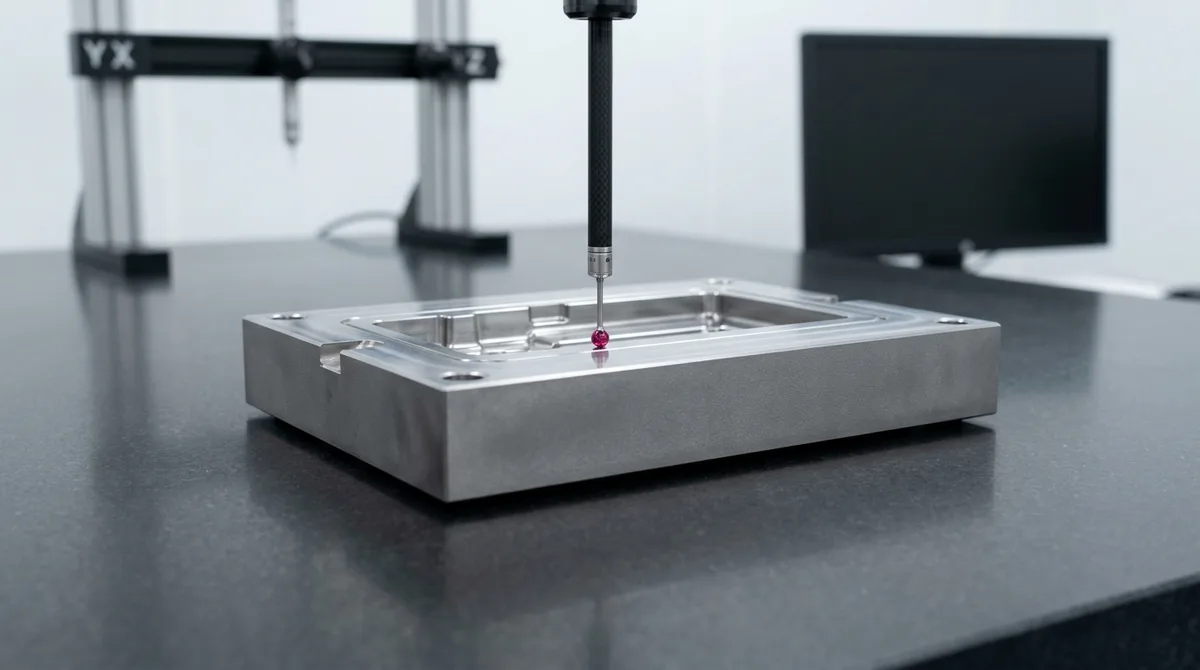
Every critical alignment bore and guide pin bushing is measured to verify conformance with ISO 2768-mK general tolerances and custom drawing tolerances (±0.010 mm to ±0.020 mm). This strict metrology protocol guarantees that the DMLS conformal insert drops seamlessly into the tool base with flawless alignment, zero water leakage, and exact core-cavity concentricity.
8. Total Cost of Ownership (TCO) & Machine-Hour Economic Break-Even
While the thermal and quality advantages of conformal cooling are undisputed, tooling decisions ultimately hinge on Total Cost of Ownership (TCO). A common misconception is that conformal cooling is always preferable or, conversely, that additive tooling is prohibitively expensive. In reality, the economic crossover between conventional and conformal cooling is determined by part geometry, resin behavior, and total production volume.
The total manufacturing cost per part (C_total) in an injection molding program is modeled as:
Where V represents total production run volume, C_tooling is the upfront mold non-recurring engineering (NRE) investment, C_material is part resin cost, R_machine is the fully loaded hourly machine rate (hourly operational rate for press, operator, auxiliary power, and chiller overhead), t_cycle is total cycle time in seconds, and N_cavities is the number of mold cavities.
The economic dynamics break down across distinct volume tiers:
- Low-Volume Prototyping & Bridge Tooling (< 10,000 units): Upfront tooling cost dominates the equation. The additional engineering, DMLS laser hours, and post-machining required for conformal inserts represent a substantial percentage of total program expense. The cycle time savings (e.g., shaving 6 seconds off 2,000 parts saves a mere 3.3 machine hours) cannot amortize the additive premium. In this volume regime, conventional machined tooling—especially rapid tooling in 7075-T651 aluminum or P20 steel—delivers the lowest total cost.
- Medium-Volume Production (10,000 to 50,000 units): Conformal cooling becomes highly competitive for parts exhibiting severe warpage risks, deep draw cores, or thick optical cross-sections. If conventional tooling requires secondary post-mold cooling fixtures, manual flame straightening, or yields scrap rates exceeding 3%, conformal cooling pays for itself purely through scrap elimination and quality yield.
- High-Volume Mass Production (> 50,000 to Millions of units): Machine-hour operating cost completely eclipses upfront tooling NRE. Consider a multi-cavity automotive housing running 300,000 cycles annually on a 250-ton electric molding press. If conformal cooling reduces cycle time from 28 seconds to 18 seconds (a 10-second reduction, or 35.7% cycle compression), it saves 833 machine hours per year. This frees up an entire quarter of machine capacity, slashes kilowatt-hour chiller consumption, and delivers full payback on the DMLS inserts within the first few weeks of full-rate production.
9. Coolant Filtration, Anti-Scaling & Closed-Loop Chiller Maintenance
A high-performance conformal cooling tool is only as effective as the fluid running through it. Because conformal passages possess smaller hydraulic diameters (Ø4 to Ø8 mm) and complex 3D sweeps compared to deep Ø12 mm gun-drilled lines, improper fluid maintenance can induce premature fouling and permanent tool damage.
To ensure multi-year, maintenance-free mold operation, toolrooms should implement four fluid quality standards:
- Closed-Loop Chilled Water Circuits: Conformal tooling should never be connected to open cooling towers or untreated municipal tap water. Hard water contains dissolved calcium and magnesium ions that rapidly form mineral scale on heated channel walls. Molds must operate on closed-loop Temperature Control Units (TCUs) filled with demineralized or reverse-osmosis (RO) water.
- High-Efficiency Microfiltration (≤ 50 μm): Inline stainless steel mesh filters (50-micron rating or finer) must be installed directly on the supply lines feeding the mold. This catches pipe rust flakes, pump seal debris, and foreign particles before they enter narrow conformal loops. Dual duplex filter housings allow filter cartridge cleaning without halting production.
- Corrosion & Biological Inhibitors: For maraging steel (1.2709) tools, coolant should be dosed with passivating corrosion inhibitors (such as molybdate or organic acid inhibitors) and a non-oxidizing biocide to prevent bacterial biofilm formation. When chilling water below 8°C, an inhibited ethylene glycol mixture (20% to 30% by volume) prevents freezing while maintaining Reynolds number turbulence.
- Periodic Chemical Cleaning & Descaling: If flow rate sensors detect an unexpected increase in circuit pressure drop (ΔP > 15% above benchmark baseline), the tool should undergo offline recirculating descaling. An inhibited citric acid or sulfamic acid solution (5% to 8% concentration at 40°C) is circulated for 60 to 90 minutes. Citric acid dissolves carbonate scale and iron oxides without attacking the underlying 1.2709 tool steel substrate, restoring pristine heat transfer performance.
10. Frequently Asked Questions: Conformal vs Conventional Cooling
Conformal cooling typically reduces total injection molding cycle time by 20% to 50%. The highest savings occur on thick-walled structural components, deep-draw boxes, automotive electrical connectors, and parts where conventional gun-drilled cooling lines cannot reach deep internal cores.
The industrial benchmark alloy is 1.2709 Maraging Steel (Maraging 300 / MS1), which reaches 50 to 54 HRC with yield strength exceeding 1,900 MPa after a 490°C precipitation aging heat treatment. For corrosive resins releasing halogen gases or acid fumes, precipitation-hardening Corrax stainless steel is specified.
Conformal channels can become clogged only if operated on dirty, untreated open-loop water. Toolmakers prevent particulate accumulation by running closed-loop chillers with demineralized water, installing 50-micron inline mesh filters, and maintaining turbulent flow (Re > 10,000) which naturally inhibits silt settling.
Conformal cooling maintains a constant 1.5d to 2.0d distance to the part skin, keeping mold surface temperature variations within ±1.5°C to ±2.0°C. Symmetrical, balanced heat extraction from both core and cavity halves eliminates differential volumetric shrinkage (ΔSv), preventing post-ejection bow, twist, and potato-chipping.
Conventional machined cooling is preferable for low-volume production (<10,000 units), flat or shallow components, and rapid prototyping bridge molds. In these applications, the additional DMLS print hours and engineering setup cannot be amortized by the modest machine-hour savings.
Accelerate Your Injection Mold Thermal Design
AS Prototypes provides advanced rapid tooling and custom injection molding solutions. Our engineering team combines transient Moldflow thermal simulations with industrial DMLS additive manufacturing to optimize cycle times and eliminate part warpage. Upload your 3D CAD files (STEP, IGES, or native CAD) to receive a comprehensive DFM thermal analysis within 24 hours.







