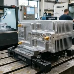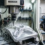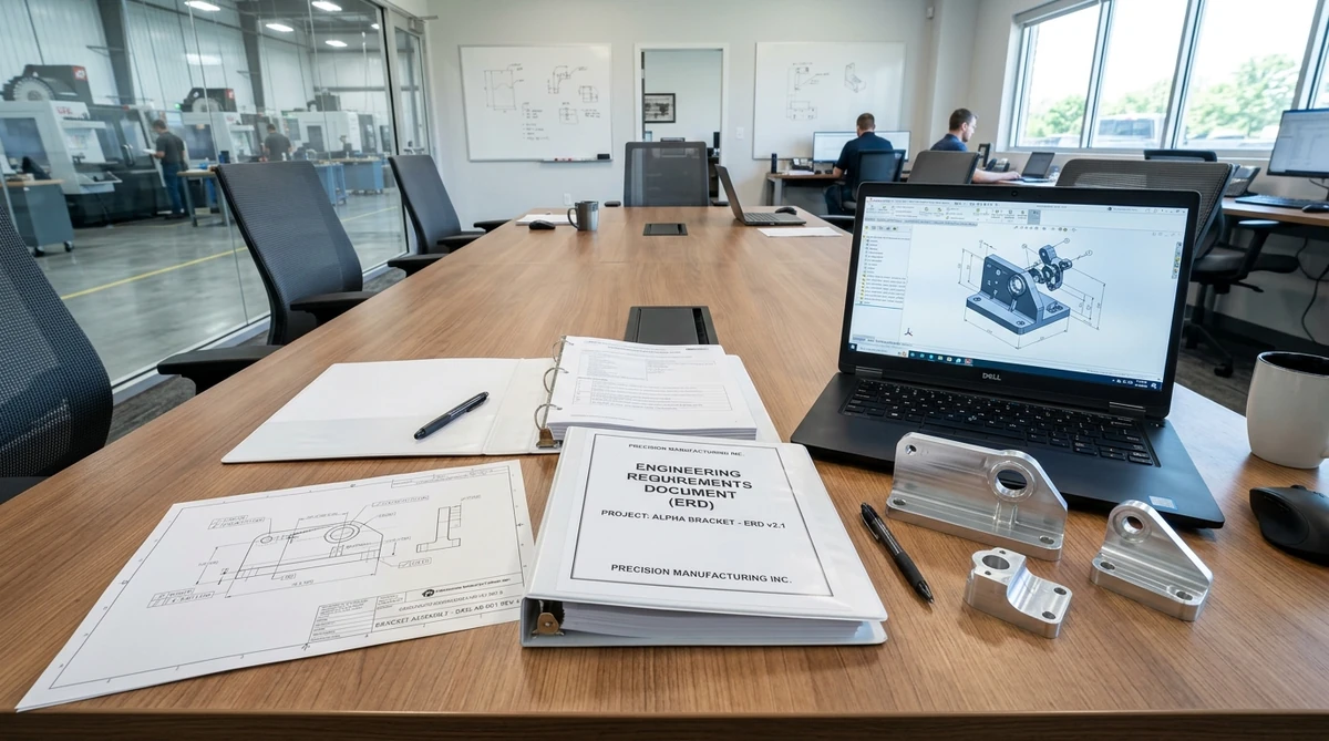
Developing custom hardware products requires unambiguous communication between design teams, manufacturing partners, and quality inspectors. An engineering requirements document (ERD) serves as the foundational technical contract that translates high-level product visions into measurable, verifiable engineering specifications. Without a rigorous ERD, prototype programs risk budget overruns, machining delays, and assembly fit failures.
While product managers outline customer needs in a Product Requirements Document (PRD), hardware engineers translate those desires into quantifiable constraints. These constraints encompass mechanical tolerances, material grades, thermal dissipation thresholds, environmental sealing standards, and production testing protocols. At AS Prototypes, our precision CNC machining solutions leverage robust ERD guidelines to ensure every prototype conforms exactly to design intent.
Core Architecture of a Hardware Engineering Requirements Document
An effective hardware ERD bridges theoretical design with practical fabrication. It establishes measurable criteria across several engineering domains:
- Physical and Geometric Constraints: Defines outer envelope dimensions, weight budgets, center-of-gravity targets, and mounting interfaces.
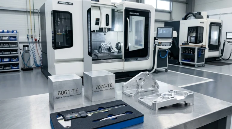
- Material and Finishing Specifications: Mandates exact alloy grades (such as 6061-T6 aluminum or 316L stainless steel), temper states, and surface treatments like Type III hardcoat anodizing or electroless nickel plating.
- Mechanical and Thermal Performance: Specifies minimum yield strengths, impact resistance, continuous operating temperature limits, and thermal expansion coefficients.
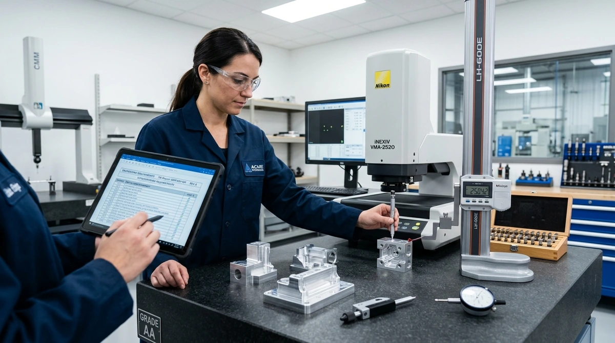
- Quality and Metrology Protocols: Outlines First Article Inspection (FAI) criteria, Coordinate Measuring Machine (CMM) inspection routines, and acceptable quality limits (AQL). Review our complete factory equipment list and CMM capabilities to explore our shop floor verification assets.
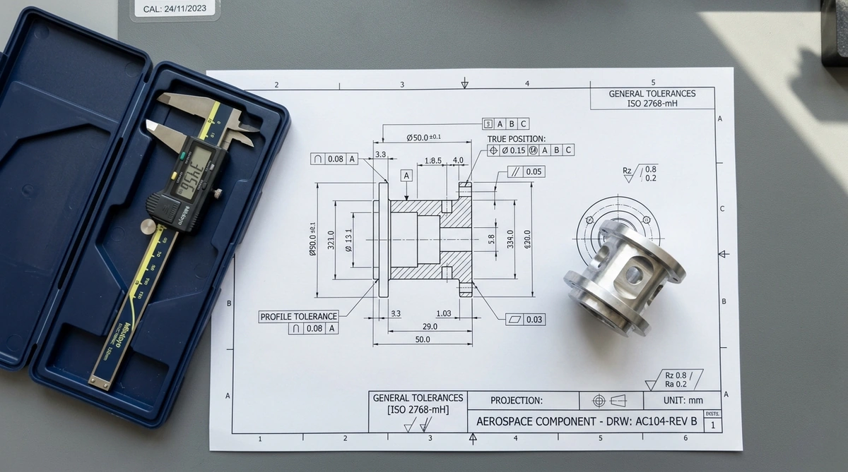
Key Sections of an Engineering Requirements Document
To avoid manufacturing ambiguities, engineering teams should structure their ERD using standardized technical modules. The table below outlines the core components of an industrial-grade hardware ERD:
| Document Module | Core Technical Objective | Mandatory Data Points | Common Pitfalls Avoided |
|---|---|---|---|
| Scope & Functional Envelope | Define boundary conditions and operating environment | Operating temp range, ingress protection (IP rating), duty cycles | Prevents premature field failures from unanticipated thermal or moisture stress |
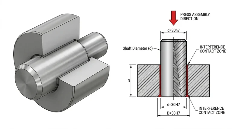
| Mechanical & GD&T Standards | Establish geometric accuracy and fit criteria | ASME Y14.5 datums, ISO 2768-mK default tolerances, critical fit limits | Eliminates tolerance stack-up errors during multi-part mechanical assembly |
| Material & Finishing Matrix | Dictate chemical composition and surface treatments | ASTM alloy standards, heat treat temper, coating thickness (μm) | Prevents supplier material substitutions and galvanic corrosion issues |
| Verification & Test Plan | Establish pass/fail inspection protocols | CMM sampling frequency, drop test specs, leak testing pressure | Eliminates post-delivery quality disputes between buyer and machine shop |
| DFM & Packaging Rules | Protect finished parts during shipping and handling | Anti-static ESD bags, custom foam trays, labeling barcodes | Avoids transit scratches on precision optical or cosmetic anodized surfaces |
Document Hierarchy: PRD vs. ERD vs. 2D Technical Drawings
In mature product development organizations, distinct documents govern different stages of the hardware lifecycle. Understanding the hierarchy ensures seamless transitions from concept to serial production:
| Document Type | Primary Author | Primary Audience | Technical Focus | Change Control Frequency |
|---|---|---|---|---|
| Product Requirements Document (PRD) | Product Manager | Cross-functional leadership, UX, Marketing | User personas, business goals, target price point | Low (Fixed after concept approval) |
| Engineering Requirements Document (ERD) | Lead Systems / Mechanical Engineer | R&D Engineers, QA, Manufacturing Partners | Subsystem specs, GD&T baselines, test standards | Moderate (Refined through prototyping EVT/DVT) |
| 2D Manufacturing Drawing | CAD Detailer / Mechanical Designer | CNC Machinists, Toolmakers, CMM Inspectors | Part-level dimensions, feature datums, surface Ra | Strict (Requires formal Engineering Change Order) |
Best Practices for Writing an Industrial-Grade ERD
When compiling an engineering requirements document, precision engineering teams should implement three golden rules:
- Use Measurable and Testable Metrics: Avoid subjective terms like “durable,” “smooth,” or “lightweight.” Instead, mandate tensile yield strength greater than or equal to 275 MPa, surface roughness Ra below 0.8 micrometers, and total assembly mass under 450 grams.
- Specify Default Standard Tolerances: Explicitly invoke international tolerance standards such as ISO 2768-mK for standard CNC milling or ISO 2768-fH for high-precision fits. This prevents machinists from guessing on non-critical dimensions while maintaining tight controls on mating interfaces.
- Establish Clear Revision Histories: Maintain strict document versioning with change tracking matrices. Clearly indicate which subsystem parameters were modified, who approved the Engineering Change Order (ECO), and how the revision impacts downstream tooling.
A Product Requirements Document (PRD) outlines what the product must do from a user and commercial perspective. In contrast, an Engineering Requirements Document (ERD) defines how engineering teams will technically realize those goals using precise physical tolerances, material choices, and validation tests.
Referencing standards like ISO 2768-mK or ISO 2768-fH establishes clear default tolerances for all dimensions not explicitly tagged with GD&T callouts. This practice eliminates shop-floor ambiguity, standardizes quality control, and prevents unnecessary manufacturing costs on non-critical features.
AS Prototypes reviews the ERD alongside your 3D CAD files to identify tight tolerances, deep cavity ratios, and challenging material requirements early. We propose minor geometric optimizations that lower cycle times and tool wear without compromising functional specifications.
Transform Your Engineering Specs into High-Precision Hardware
Have an engineering requirements document and 3D CAD models ready for prototyping or production? AS Prototypes provides expert Design for Manufacturability (DFM) reviews, CNC machining, rapid tooling, and certified CMM inspection reports. Upload your CAD drawings (STEP, IGES, or PDF) to receive actionable manufacturing feedback and a rapid RFQ within 24 hours.