

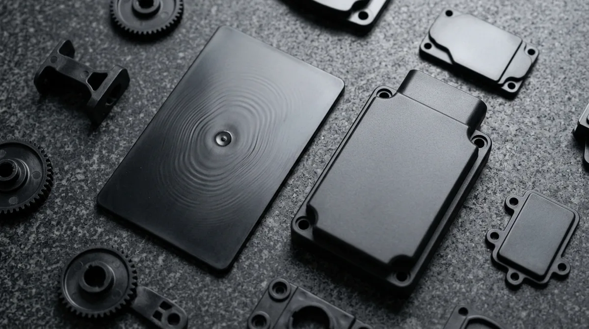
- Core Focus & DFM Scope: Actionable shop-floor engineering guidelines for flow mark in injection molding, covering material selection, geometric tolerancing, and defect prevention.
- Dimensional Tolerance Baseline: General molded/cast features hold ISO 2768-mK or ±0.05 to ±0.10 mm (±0.002″ to ±0.004″); critical post-machined datum bores achieve ±0.010 mm (±0.0004″).
- Tooling & Surface Integrity: Cavity surfaces finished from SPI A-2 mirror polish (Ra 0.05 µm / 2 µin) to VDI 3400 spark-eroded textures with mandatory 1.0°–2.5° draft angle compensation.
- Metrology & Flow Validation: Pre-tooling DFM and rheological fill simulation paired with Zeiss CMM first-article inspection (FAI) and wall-thickness ultrasonic/section verification.
- Ex-Factory Turnaround: 7 to 12 business days for vacuum cast/urethane bridge batches; 18 to 35 business days for rapid aluminum/P20/H13 tooling and T1 sample delivery (excluding 3–5 days air transit).
Engineering Takeaways: Eliminating Flow Marks in Injection Molding
Bottom Line Up Front (BLUF): A flow mark in injection molding is a cosmetic boundary defect triggered when the molten polymer skin freezes prematurely against cold mold steel before the cavity is fully packed. Solving persistent flow marks requires a decoupled three-tier strategy: First, tune multi-stage injection velocity profiling to prevent melt hesitation at gate entry; Second, elevate mold temperature and verify turbulent cooling circuit flow (ΔT < 3°C); Third, apply permanent tooling DFM fixes including flared fan gates, enlarged cold slug wells, and gradual 3:1 wall thickness blending transitions.
Cosmetic surface perfection directly determines commercial success in consumer electronics, automotive interiors, and medical device enclosures. However, visible surface imperfections such as wavy ripples, gate blush, and gloss disparity frequently trigger costly production halts.
Eliminating a flow mark in injection molding requires a rigorous understanding of polymer rheology, fountain flow physics, and cavity heat transfer dynamics. When molten resin cools unevenly during cavity filling, the advancing melt front hesitates, leaving distinct concentric waves or dull patches on the finished part.
At AS Prototypes, our tooling engineers and processing technicians apply scientific decoupled molding principles across our custom injection molding services. By combining advanced Moldflow simulation with precision CNC-machined mold cavities, we eliminate cosmetic defects before production begins. In addition, we apply calibrated EDM textures and bead-blast finishes per SPI surface finish standards to deliver pristine molded components.
This technical guide provides a practical troubleshooting roadmap for tooling engineers, mold designers, and manufacturing specialists. We examine polymer rheology mechanisms, resin sensitivity comparisons, decoupled velocity profiling, tooling DFM guidelines, and automated metrology inspection methods.
What Causes Flow Marks: Fountain Flow Rheology and Premature Skin Freezing
Fundamentally, a flow mark in injection molding represents a frozen thermal boundary layer preserved on the molded component exterior. To diagnose the defect accurately, process engineers must analyze the laminar flow behavior of molten resin inside closed tool steel cavities.
Inside an injection mold cavity, thermoplastic resin advances through a fluid dynamics mechanism known as fountain flow. In fountain flow, the hottest, lowest-viscosity molten plastic travels down the center core of the flow channel at high velocity. As this molten core reaches the advancing front, it rolls outward toward the cold cavity steel walls like a rolling fountain.
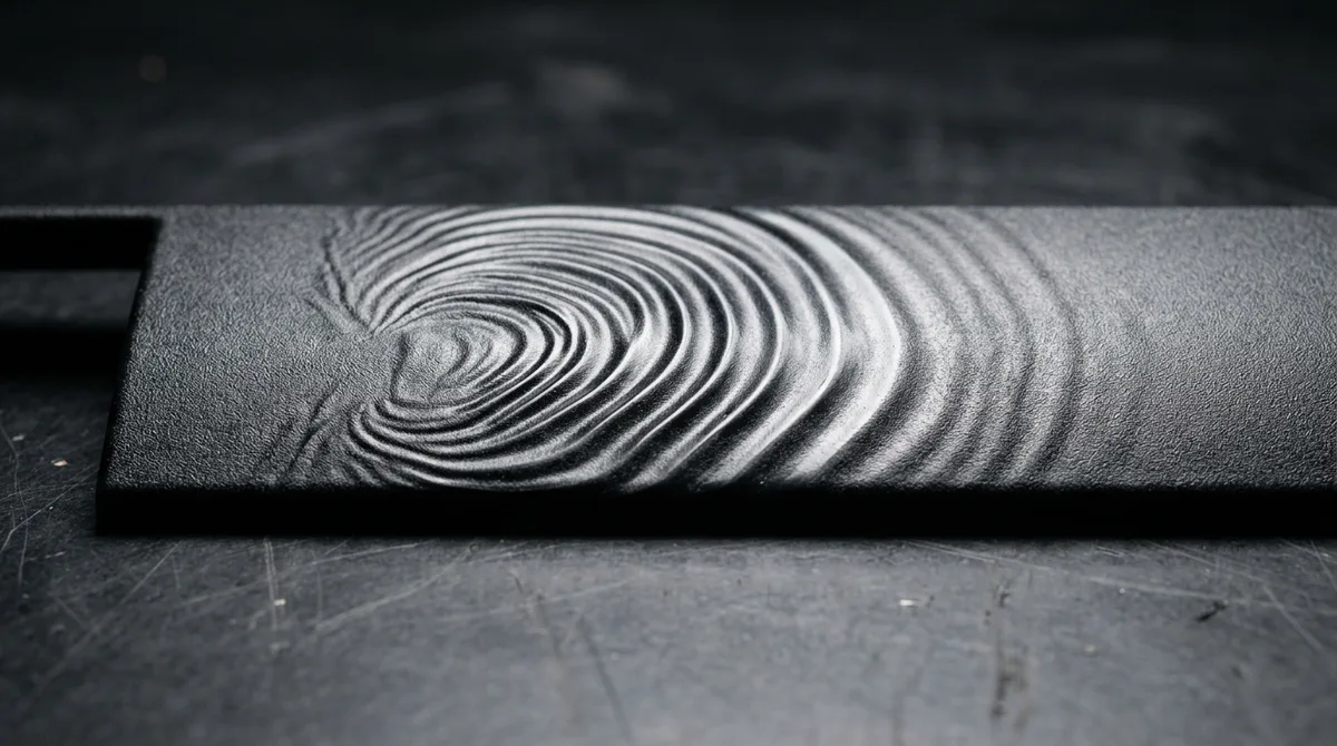
When the advancing polymer contacts the colder mold steel, heat transfers rapidly into the tool. Under optimal processing conditions, continuous forward velocity maintains sufficient dynamic pressure to press the polymer skin firmly against the mold texture. This rapid, uninterrupted packing accurately replicates the cavity surface finish.
However, if the melt front velocity drops below a critical threshold, the outer resin skin cools below its glass transition temperature (Tg) or crystallization temperature prematurely. When this occurs, the outer skin stiffens into a semi-rigid membrane while cavity filling is still underway.
As the injection screw continues forward movement, fresh hot polymer from the core surges behind the stalled skin. The fresh melt buckles and rolls over the frozen boundary, creating a physical wave crest and trough. On the finished part, this periodic hesitation manifests as visible concentric ripples, often referred to by molders as phonograph record grooves or tiger stripes.
In workshop environments, engineers encounter four distinct morphological variants of flow defects, each governed by different rheological triggers:
- Concentric Record Grooves (Melt Hesitation): Wavy, ring-shaped ripples radiating outward from the gate, caused by periodic flow front hesitation and uneven cavity filling velocity.
- Gate Blush and Halo Disparity: A cloudy, high-gloss or dull haze surrounding the gate vestige, caused by excessive shear stress and localized frictional overheating as resin squeezes through a restricted gate orifice.
- Cold Slug Smudges: Irregular, crescent-shaped dull smudges appearing downstream from the gate, caused when chilled plastic from the machine nozzle tip is swept into the cavity.
- Wall-Thickness Step Shadows: Linear gloss disparity lines running perpendicular to melt flow across abrupt thickness transitions, caused by sudden velocity changes and localized pressure drops.
| Defect Classification | Physical Root Cause | Visual Manifestation | Primary Engineering Remedy |
|---|---|---|---|
| Concentric Hesitation Rings | Fountain flow stall and premature skin freeze | Wavy ripple ridges concentric with gate | Increase injection velocity profile; raise mold steel temp. |
| Gate Blush & Shear Halo | Extreme shear rate across narrow gate land | Radial haze or halo disparity around gate orifice | Enlarge gate depth; profile slow injection entry speed. |
| Serpentine Jetting Lines | Melt stream squirts into open cavity without wall impingement | Wiggly worm-like snake tracks on surface | Reorient gate toward cavity wall or core pin; widen gate land. |
| Cold Slug Streaks | Chilled nozzle tip slug enters cavity stream | Dull localized streak or crescent near gate | Enlarge cold slug well volume at sprue and runner turns. |
| Thickness Step Shadow Lines | Abrupt cross-sectional area expansion/reduction | Linear gloss contrast band along step boundary | Blend transitions with 3:1 chamfers or gradual radius tapers. |
Material Rheology: Resin Sensitivity and Viscosity Dynamics
Thermoplastic resins exhibit vastly different flow characteristics under equivalent molding temperatures and pressures. Understanding resin-specific melt flow index (MFI) and molecular architecture is essential when designing molds to prevent flow defects.
Polymers divide into two fundamental structural categories: amorphous polymers and semi-crystalline polymers. Amorphous resins, including Polycarbonate (PC), Acrylonitrile Butadiene Styrene (ABS), Polymethyl Methacrylate (PMMA), and Polystyrene (PS), are substantially more vulnerable to flow marks and gloss disparity than semi-crystalline resins.
Amorphous polymers lack a sharp, distinct melting point. Instead, they soften gradually across a broad glass transition range. Because amorphous resins possess high molecular entanglement and high melt viscosity, their viscosity responds steeply to minor temperature drops along the cavity wall.
For example, optical-grade Polycarbonate (PC) requires high melt temperatures (280°C to 315°C) and mold temperatures (80°C to 115°C). If mold steel temperature drops slightly below 75°C, PC skins freeze almost instantly upon cavity entry. The resulting hesitation lines cannot be ironed out by pack pressure, permanently scarring cosmetic bezels.
In contrast, semi-crystalline materials such as Polypropylene (PP), Polyamide (PA66, PA6), and Polyoxymethylene (POM / Acetal) possess sharp melting points and lower melt viscosities. When molten, their polymer chains flow readily through thin cross sections. However, semi-crystalline materials undergo significant volumetric shrinkage during crystallization. If the flow front hesitates, localized crystal morphology varies, causing optical reflectance differences that mimic flow marks.
| Resin Classification | Polymer Structure | Standard Melt Temp Range | Recommended Mold Temp | Flow Mark Vulnerability |
|---|---|---|---|---|
| Polycarbonate (PC) | Amorphous (High Viscosity) | 280°C to 315°C | 80°C to 115°C | Critical (Severe hesitation risk) |
| PC/ABS Blend | Amorphous Alloy | 240°C to 270°C | 60°C to 90°C | High (Gloss disparity near gates) |
| ABS Standard | Amorphous Terpolymer | 220°C to 250°C | 50°C to 75°C | Moderate (Correctable via velocity) |
| PMMA (Acrylic) | Amorphous Optical Grade | 220°C to 260°C | 60°C to 85°C | High (Optical distortion rings) |
| Nylon (PA66 / PA6) | Semi-Crystalline | 260°C to 295°C | 70°C to 105°C | Low to Moderate (Fiber orientation marks) |
| Polypropylene (PP) | Semi-Crystalline | 200°C to 240°C | 30°C to 60°C | Low (Tiger striping on long flow lengths) |
Furthermore, fiber-reinforced materials (such as PA66-GF30 or PC-GF20) present compound challenges. When molten glass-filled resin enters the cavity, glass fibers orient along the shear boundary layer. If the flow front hesitates, fibers freeze in random orientations, causing severe silver-white streak patterns and pronounced surface roughness.
Scientific Molding Process Parameter Tuning (Decoupled II/III Strategy)
When flow marks appear during pre-production sampling, processing technicians frequently make haphazard machine adjustments, trading flow marks for parting line flash or burn marks. In contrast, scientific molding applies decoupled methodology to isolate filling from packing.
In Decoupled II molding, 95% to 98% of the cavity volume is filled strictly under injection velocity control. Once the screw reaches the transfer position (V/P switchover), machine control transfers immediately to hydraulic packing pressure. This ensures that melt front progression remains independent of mold cavity resistance.

Tuning the multi-stage injection velocity profile is the most effective machine adjustment for eradicating flow lines without altering mold steel. Our technicians configure a controlled three-stage filling profile:
- Stage 1 (Controlled Gate Entry): Inject at low to moderate velocity (15 mm/s to 30 mm/s) as resin traverses the narrow gate orifice. This controlled entry prevents jetting, excessive shear heating, and gate blush.
- Stage 2 (Rapid Cavity Filling): Accelerate sharply to high velocity (60 mm/s to 140 mm/s) once the flow front clears the gate land. High velocity maintains shear thinning behavior and prevents premature skin freezing across expansive wall surfaces.
- Stage 3 (Controlled Deceleration Before V/P): Decelerate smoothly during the final 5% of cavity fill. This prevents dynamic pressure spikes, eliminates parting line flash, and allows clean gas venting through parting line vents.
Beyond velocity profiling, thermal management plays a decisive role in eliminating frozen boundary layers. Increasing mold temperature controller (MTC) settings warms the mold steel surface above the resin skin freeze threshold. This permits the advancing polymer fountain flow to wet the steel smoothly.
However, elevating mold temperature without verification can extend cooling cycles unnecessarily. Technicians must verify turbulent flow inside mold cooling circuits. Turbulent flow (Reynolds number Re > 4,000) achieves three to five times higher heat transfer efficiency than laminar flow, keeping cavity steel temperatures uniform within ΔT < 3°C across all impressions.
| Process Variable | Target Adjustment Action | Recommended Incremental Step | Engineering Overcorrection Risk |
|---|---|---|---|
| Injection Fill Velocity | Increase Stage 2 cavity velocity profile | +15% to +25% increments | Excessive shear heating, gas burns, or flash. |
| Mold Steel Temperature | Raise water circuit temperature controller | +5°C to +15°C increments | Longer cooling cycle times and part warpage. |
| Barrel Melt Temperature | Increase front zone and nozzle heater bands | +5°C to +10°C increments | Thermal degradation, yellowing, and splay. |
| Holding Pressure Profile | Increase initial packing pressure stage | +10% to +20% increments | Overpacking, part sticking, and high residual stress. |
| Back Pressure | Elevate screw recovery back pressure | +0.5 MPa to +1.5 MPa | Screw recovery slippage and resin shear heating. |
Barrel temperature zoning must maintain a gradual forward thermal progression. Feed zone temperatures should remain cooler to facilitate pellet conveyance, while compression, metering, and nozzle zones reach homogeneous processing temperatures. Nozzle temperature must match the melt pool to eliminate cold resin droplets at the sprue bushing.
Tooling DFM Rules: Gate Geometry, Runner Layout, and Cold Slug Wells
While process parameter optimization resolves minor flow lines, persistent cosmetic defects originate from inadequate mold design. Modifying cutting tool paths and steel geometry eliminates the root causes of melt hesitation permanently.
Gate selection dictates how resin transitions from high-pressure runner channels into the cavity. Undersized gates generate high pressure drops and excessive shear rates. When high-velocity resin exits a pinhole gate into an expansive cavity, it squirts uncontrollably across the core like a garden hose, causing severe jetting snake lines.
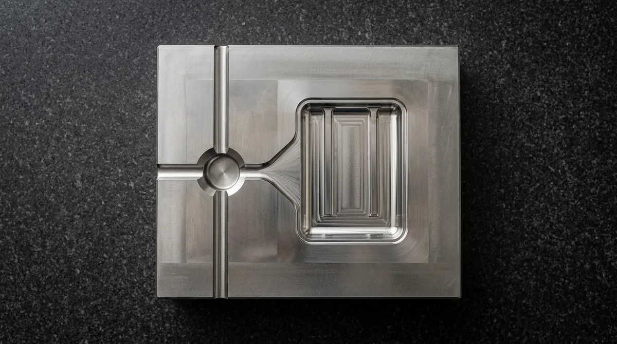
To eliminate jetting and hesitation rings on flat panels and housings, mold designers apply flared fan gates or wide edge gates. A fan gate widens gradually from the runner channel to the cavity edge, distributing melt evenly across a wide front. This maintains laminar flow, suppresses shear peaks, and delivers a uniform filling front.
Gate land length represents another critical tooling parameter. Gate land length should never exceed 0.8 mm to 1.0 mm. Excessively long gate lands cause substantial pressure drops and premature cooling within the gate channel itself, robbing the cavity of thermal energy.
Runner layout and cold slug well geometry must receive equal attention during DFM review. When the machine injection cycle begins, the cold plastic droplet sitting at the nozzle tip enters the sprue first. If this cold plug enters the mold cavity, it chills on the part surface, producing localized cold slug streaks and flow blemishes.
To prevent this contamination, every runner intersection and sprue turn requires an enlarged cold slug well. Cold slug wells should extend beyond the runner junction by a depth equal to 1.0 to 1.5 times the runner diameter. Incorporating a Z-pin or undercut sucker pin at the base of the well locks the cold slug in place, ensuring only pristine, homogeneous melt enters the gate.
| Gate Type | Recommended Application | Standard Dimension Rules | Flow Mark Prevention Benefit |
|---|---|---|---|
| Edge Fan Gate | Large flat bezels, covers, and housings | Width: 25% to 50% part width; Depth: 50% to 75% wall thickness | Distributes melt uniformly across wide front; eliminates jetting. |
| Submarine (Tunnel) Gate | Automatic degating, cosmetic exterior faces | Orifice Ø0.8 mm to Ø1.6 mm; 30° to 45° sub-angle | Injects below parting line; hides gate vestige on interior ribs. |
| Direct Sprue Gate | Single-cavity deep buckets and containers | Taper: 2° to 4°; Orifice Ø3.5 mm to Ø6.0 mm | Delivers maximum packing pressure directly to central thick sections. |
| Valve Gate Hot Runner | Multi-cavity medical and automotive parts | Tip orifice Ø1.2 mm to Ø2.5 mm; pneumatic/hydraulic actuation | Sequential valve gate (SVG) timing minimizes visible weld lines and hesitation rings. |
Finally, cavity venting must never be neglected. When molten resin fills a closed steel cavity, trapped air must escape rapidly. If venting is restricted, compressed air creates counter-pressure, stalling the melt front and causing hesitation lines or dieseling burn marks. Precision ground vents (0.025 mm to 0.040 mm deep for ABS/PC) along the parting line ensure uninhibited cavity exhaust.
Part Geometry and Wall Thickness Transitions: DFM Guidelines
Plastic component geometry dictates flow path resistance. Even the most sophisticated injection press and mold tooling cannot overcome severe part design deficiencies, such as abrupt wall thickness variations.
Uniform nominal wall thickness is the primary rule of plastic part design. When resin flows from a thick section into a thin wall, flow resistance increases sharply. The polymer stream hesitates in the thin section while continuing to fill the thick channel, creating frozen boundary lines along the transition.
Conversely, when resin flows from a thin wall into an abrupt thick section, the sudden volume expansion causes the flow front to lose dynamic pressure and stagger. This pressure drop manifests as an unsightly shadow line or gloss disparity band across the exterior surface.
When engineering requirements demand variable wall thicknesses, designers must incorporate gradual transitions following the 3:1 transition rule. The length of the tapered transition must measure at least three times the thickness difference (Δt). Blending all sharp interior corners with generous radii (R ≥ 0.5 × wall thickness) preserves laminar flow dynamics.
| Design Feature | Recommended DFM Standard | Risk of Non-Compliance |
|---|---|---|
| Nominal Wall Thickness | Maintain within ±15% uniform variation across part | Differential cooling rates, sink marks, and flow hesitation lines. |
| Thickness Step Transition | Minimum 3:1 chamfer taper ramp with blended radii | Abrupt pressure drops resulting in surface gloss shadow banding. |
| Rib Root Thickness | Set rib base to 40% to 60% of nominal adjacent wall | Localized hot spots causing sink marks and flow hesitation shadows. |
| Corner Fillet Radii | Internal radius R ≥ 0.5t; External radius R ≥ 1.5t | Stress concentrations and turbulent melt vortex rings. |
| Flow Length Ratio (L/t) | Maintain within resin flow limit (e.g., L/t < 150:1 for PC) | Severe pressure drop and premature freezing before cavity packing. |
Additionally, structural reinforcing ribs and screw bosses must adhere to strict thickness ratios. Designing ribs with a base thickness exceeding 60% of the nominal wall creates a localized thermal mass. This thermal disparity delays cooling in the intersection, triggering both sink marks on the Class-A face and flow hesitation marks as the melt front bypasses the rib opening.
Quality Inspection, Metrology, and Surface Finish Camouflage
Detecting and quantifying flow mark defects requires calibrated metrology instruments rather than subjective visual inspection under ambient shop lighting.
In our metrology laboratory, quality technicians inspect molded components using multi-angle gloss meters per ASTM D523 standards. By recording gloss levels at a 60° geometry across a grid of measurement points, technicians map gloss disparity across the part surface. A gloss variation exceeding 5 gloss units (GU) on a cosmetic exterior indicates uncorrected melt hesitation.

High-magnification optical stereomicroscopes examine the gate vestige and runner shear areas. Examining the micro-topography reveals whether polymer chains suffered thermal shear degradation during gate passage or experienced physical tearing during mold opening.
Furthermore, mold surface texture selection provides an effective engineering solution for masking subtle flow lines on consumer products. While mirror-polished SPI-A2 finishes highlight every microscopic gloss variation, textured mold surfaces disperse specular reflections.
Applying electrical discharge machining (EDM) textures (such as VDI 3400 grades #24 to #30) or bead-blasted SPI-D1 finishes creates an isotropic micro-roughness. This microscopic texture scatters incoming light, rendering subtle hesitation waves virtually invisible to the naked eye while maintaining tight dimensional tolerances (±0.050 mm to ±0.100 mm).
Comprehensive Troubleshooting Decision Matrix for Workshop Engineers
When diagnosing surface defects on the production floor, quick-reference guides prevent trial-and-error downtime. The troubleshooting matrix below summarizes immediate machine parameter adjustments and permanent tooling DFM remedies for each flow mark variant:
| Defect Symptom | Underlying Mechanism | Immediate Machine Adjustment (5-Min Trial) | Permanent Tooling DFM Action |
|---|---|---|---|
| Concentric Wavy Rings Near Gate | Premature skin freeze and melt front hesitation | Increase injection fill speed; raise mold water circuit temp by 10°C. | Enlarge gate cross section; shorten gate land length (≤ 0.8 mm). |
| Dull Gate Blush / Halo | Excessive shear stress through narrow orifice | Profile slow injection entry velocity as resin passes gate. | Increase gate orifice diameter; polish gate entry radius. |
| Snake-Like Serpentine Jetting | Melt squirts through open cavity without wall impingement | Significantly reduce initial injection speed until gate seals. | Reorient gate against mold cavity wall or standing core pin. |
| Localized Dull Cold Slug Smudges | Chilled nozzle tip resin enters cavity | Increase nozzle heater band temperature; check nozzle seating. | Enlarge cold slug well volume at sprue base and runner junctions. |
| Shadow Lines at Wall Steps | Flow hesitation across sudden wall thickness expansion | Increase Stage 2 cavity injection speed and holding pressure. | Incorporate gradual 3:1 chamfer taper ramp along thickness transition. |
| Tiger Striping on Long Runs | Unstable elasticity-driven flow oscillation in PP/TPO | Optimize melt and mold temperatures; reduce injection velocity. | Relocate gates to shorten flow length; switch to lower molecular weight resin. |
The quickest machine adjustment is increasing the injection fill speed and raising the mold temperature controller (MTC) setting by 10°C to 15°C. High fill speed maintains shear thinning and keeps the advancing melt front hot, preventing the polymer skin from freezing prematurely against cold mold steel.
Undersized gates cause severe pressure drops and high shear rates, triggering gate blush and halo discoloration. Additionally, gating directly into open cavity areas causes jetting snake lines, while excessively long gate lands rob the melt of thermal energy before cavity entry. Wide fan gates and radiused edge gates provide the most uniform filling.
Yes, applying an isotropic electrical discharge machining (EDM) texture such as VDI 3400 grades #24 to #30 or a bead-blasted SPI-D1 finish scatters light reflections. This optical diffusion effectively camouflages subtle hesitation marks on cosmetic housings while preserving part tolerances.
Amorphous polymers like PC have wide glass transition ranges and high melt viscosities that increase steeply upon minor cooling. Semi-crystalline resins like PP have lower melt viscosities and sharper melting points, enabling them to fill thin walls more easily before freezing occurs.
A flow mark is a single-front hesitation wave caused by premature surface cooling and rolling fountain flow. A weld line (or knit line) forms when two separate melt fronts meet and fuse together after flowing around an obstacle such as a core pin or hole.
Struggling with Injection Molding Cosmetic Defects?
AS Prototypes delivers scientific injection molding, precision mold tooling, and comprehensive Moldflow DFM simulation. Upload your 3D CAD models today for free DFM engineering review and a detailed production quotation within 24 hours.
Request Moldflow DFM Review & Quotation






