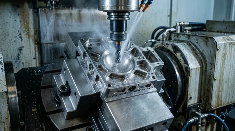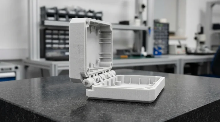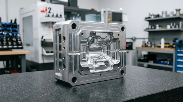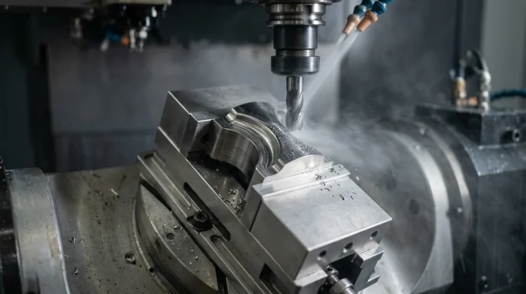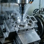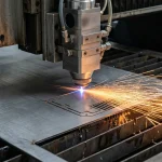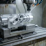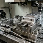
In precision manufacturing, machining capabilities have advanced at an unprecedented pace. Modern multi-axis CNC machining centers, high-speed wire EDMs, and ultra-precision diamond turning lathes routinely achieve positioning accuracies within single-digit micrometers (±0.005 mm or better). However, a fundamental tenet of precision engineering states: if you cannot measure a feature with verified metrological traceability, you cannot manufacture it with confidence.
Traditional manual inspection instruments—such as vernier calipers, external micrometers, bore micrometers, and height stands—remain indispensable on the shop floor for rapid in-process checks. Yet, when verifying complex geometric dimensioning and tolerancing (GD&T) callouts across multi-faceted 3D freeform surfaces, true position hole patterns relative to composite datum reference frames, or deep internal contours, manual tools fall short. They introduce manual operator parallax error, lack thermal compensation, and are incapable of mathematical spatial alignment. This is where the Coordinate Measuring Machine (CMM) serves as the supreme metrological arbiter in modern CNC manufacturing. This comprehensive guide explores the working mechanics, probing physics, architectural variants, and GD&T verification strategies that make CMM inspection the backbone of modern quality assurance.
1. Working Principles: Transforming Physical Touch into 3D Spatial Vectors
At its fundamental level, a Coordinate Measuring Machine is an electro-mechanical digitizer. It translates the physical envelope of a manufactured part into an array of discrete, mathematically referenced three-dimensional Cartesian coordinates (X, Y, Z). By evaluating thousands of spatial data points against the nominal 3D CAD model (STEP/IGES), CMM metrology software (such as PC-DMIS, High-precision CALYPSO, or PolyWorks) reconstructs the exact geometric form, size, orientation, and location of every feature.
The Anatomy of Precision: Four Core Subsystems
- Monolithic Granite Base and Guideways: The machine foundation consists of naturally aged, precision-lapped black granite (Grade 00 or laboratory grade). Granite offers high structural rigidity, excellent internal vibration damping, zero internal residual stress, and a low thermal expansion coefficient (α ≈ 5–6 × 10⁻⁶/K), ensuring a mechanically stable reference datum.
- Frictionless Pneumatic Air Bearings: Rather than utilizing mechanical ball screws or linear roller rails that introduce mechanical friction, stick-slip hysteresis, and wear over time, CMM axes float on frictionless air bearings. Pre-filtered compressed air (Class 1 oil and moisture per ISO 8573-1) creates a micro-air cushion (3 to 5 μm clearance) over ground granite ways, enabling smooth, micron-level motion.
- High-Resolution Optical Encoders: Each Cartesian axis features Zerodur or gold-plated glass diffraction scales monitored by electro-optical readheads, delivering linear position resolution down to 0.05 μm (50 nanometers).
- Motorized Indexable Probe Head and Sensors: Positioned at the end of the vertical Z-axis quill, motorized probe heads (such as the Renishaw PH10M or continuous 5-axis PH20/REVO systems) articulate probe styli into hundreds of repeatable compound spatial angles (A-axis ±105°, B-axis 360°) to measure complex undercuts without re-fixturing the workpiece.
2. Probing Physics: Touch-Trigger, Continuous Scanning & Optical Sensors
The sensor interface between the CMM and the workpiece dictates both measuring speed and dimensional uncertainty:
Touch-Trigger Probing (Kinematic Resistance)
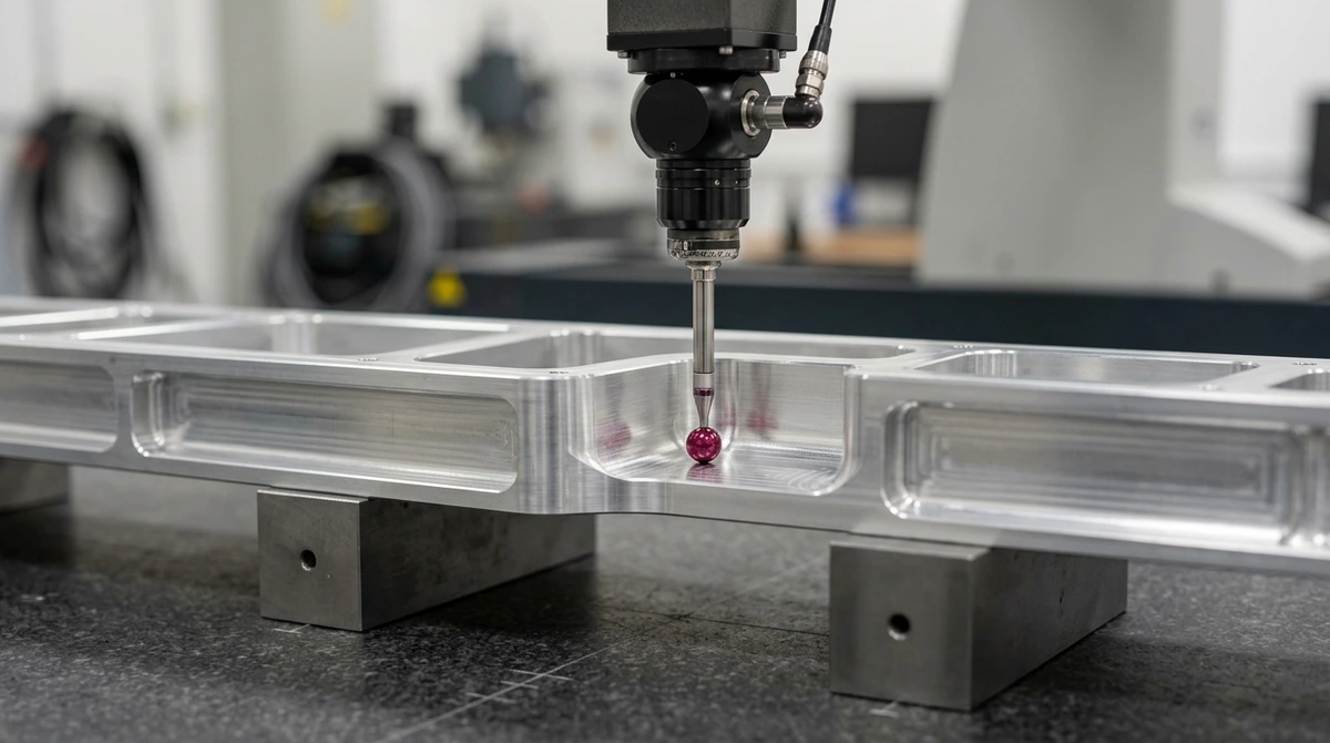
Touch-trigger probes (e.g., Renishaw TP20 and TP200) utilize a kinematic seating mechanism consisting of three sprung electrical contacts resting in V-grooves. When the spherical synthetic ruby ball stylus contacts the workpiece surface, the stylus deflects, breaking the kinematic contact circuit. The sudden jump in electrical resistance triggers an ultra-fast hardware latch, freezing the X, Y, and Z optical scale registers within sub-microseconds. Touch-trigger probing is exceptionally reliable for discrete point capture on prismatic blocks, hole centerlines, and planar surfaces.
Continuous Contact Scanning Probing
For high-precision aerodynamic airfoils, turbine blades, optical reflectors, and bearing bores, discrete point probing is insufficient to capture form deviations. Continuous scanning probes (such as the Renishaw SP25M or High-precision VAST) maintain continuous microscopic contact with the workpiece, sweeping across contours while recording 500 to 2,000 spatial points per second. Analog inductive or optical transducers inside the probe head dynamically measure stylus deflection in three axes, allowing algorithms to filter out surface micro-roughness while faithfully reconstructing circularity, runout, and surface profile.
Hybrid Non-Contact Optical and Laser Line Scanners
When measuring delicate sheet metal stampings, elastomeric rubber seals, or ultra-thin medical plastics that deflect under touch probe forces (typically 0.05 to 0.15 N), non-contact optical sensors—including blue-light line lasers and high-resolution CMOS vision cameras—capture dense point clouds without exerting mechanical load.
3. Architectural Configurations of Coordinate Measuring Machines
The kinematic architecture of a CMM determines its structural stiffness, volumetric measuring volume, and measurement throughput:
- Moving Bridge CMM: The most prevalent architecture in precision CNC machine shops. A rigid U-shaped bridge moves along the Y-axis over a stationary granite table, while the carriage and quill traverse the X and Z axes. Offers the highest stiffness-to-cost ratio for measuring parts within a 500 × 700 × 500 mm to 1,500 × 2,500 × 1,000 mm volume, delivering volumetric length measurement errors down to E0,MPE = 1.2 + L/350 μm.
- Fixed Bridge CMM: The bridge remains rigidly anchored to the base casting while the workpiece table moves along the Y-axis. Eliminating moving bridge yaw and inertial deflection enables ultra-high metrology accuracy (E0,MPE < 0.5 μm), making it the gold standard for calibrating master ring gauges, plug gauges, and high-precision aerospace bearings.
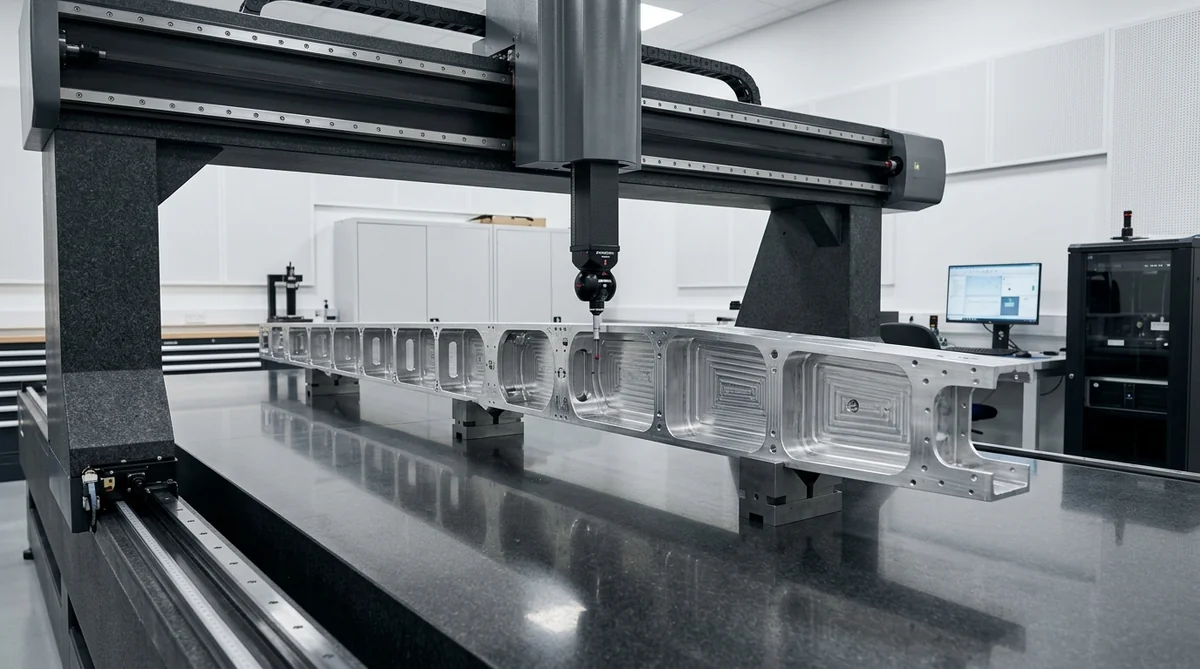
- Gantry CMM: Designed for massive structural components—such as aircraft monolithic wing spars, automotive powertrain dies, and aerospace rocket frame rings. Dual elevated guideways suspend a massive overhead bridge, leaving the shop floor unobstructed for crane loading of workpieces exceeding 5,000 to 10,000 kg.
- Cantilever & Horizontal Arm CMM: Features an open three-sided workspace where the measuring arm extends horizontally. Extensively utilized in automotive body-in-white (BIW) inspection, sheet metal weldments, and large chassis frames.
- Portable Articulated Measuring Arms: Multi-axis counterbalanced carbon-fiber arms equipped with absolute rotary encoders. While offering lower accuracy (±0.025 mm) than stationary bridge CMMs, they provide invaluable in-situ verification directly inside CNC machine enclosures before un-clamping raw billets.
4. Comprehensive Engineering Comparison: CMMs vs. Shop Floor Metrology
The following engineering matrix evaluates performance, volumetric uncertainty, throughput, and GD&T capabilities across standard precision metrology systems:
| Metrology System | Volumetric Uncertainty (MPEE) | Measurement Volume | Point Acquisition Rate | Thermal Sensitivity | GD&T Capability (ASME Y14.5) | Typical Manufacturing Role |
|---|---|---|---|---|---|---|
| Moving Bridge CMM (Contact) | 1.0 to 2.5 μm + L/350 | Medium (up to 1.5 × 2.5 × 1.0 m) | 1 to 500 pts/sec | High (Requires 20°C ±0.5°C lab) | Complete (True position, profile, runout) | First Article Inspection (FAI), final metrology validation, tight CNC tolerances |
| Fixed Bridge Metrology CMM | 0.4 to 0.8 μm + L/500 | Small to Medium (up to 1.0 × 1.0 × 0.8 m) | Up to 1,000 pts/sec | Extreme (Class 1 metrology room) | Micron-Level Verification (Down to ±0.002 mm) | Master gauge calibration, aerospace gyros, medical implants, lens molds |
| Gantry-Type CMM | 3.5 to 6.0 μm + L/250 | Very Large (up to 4.0 × 10.0 × 2.5 m) | Up to 500 pts/sec | Moderate (Real-time dynamic sensors) | Complete (Large Datums & MMC) | Aircraft wing spars, turbine casings, satellite frames, large stamping dies |
| 3D Optical Blue-Light Scanner | 10 to 30 μm | Flexible (0.1 to 3.0 m) | 2,000,000+ pts/scan | Low to Moderate | Excellent for Surface Profile (Color Map) | Organic castings, sheet metal spring-back inspection, reverse engineering |
| Portable Articulated Arm | 20 to 50 μm | Medium (Spherical reach 1.5 to 3.5 m) | Point-by-point / Laser scanning | Low (Shop-floor resilient) | Moderate (Basic GD&T Callouts) | On-machine setup verification, weldment inspection, quick prototype check |
| Manual Plate & Height Stand | 5 to 15 μm (operator-dependent) | Limited to surface plate size | Manual single reading | Moderate | Limited (Linear height, 1D flatness) | In-process Precision CNC fixture checks, quick step height verification, setup alignment |
5. Mastering GD&T Verification on Complex Workpieces
The defining capability of a CMM is its native alignment mathematical engine, which enables full evaluation of Geometric Dimensioning and Tolerancing (GD&T) according to ASME Y14.5 and ISO 1101 standards:
1. Mathematical Datum Alignment (3-2-1 Principle)
Unlike manual inspection where physical vices and angle plates must align the workpiece to physical axes, CMM software establishes a virtual mathematical coordinate frame:
- Primary Datum (Plane): Probing a minimum of three non-collinear points establishes the spatial plane, locking three degrees of freedom (pitch, roll, and Z translation).
- Secondary Datum (Line / Axis): Probing two points defines an orientation vector, locking two degrees of freedom (yaw and Y translation).
- Tertiary Datum (Point): A single point probe locks the remaining degree of freedom (X translation).
2. True Position with Material Condition Modifiers (MMC / LMC)
Calculating the true position of a hole pattern using manual height gauges requires complex, error-prone trigonometric math. On a CMM, probing each hole measures both actual diameter and Cartesian coordinates. When engineering drawings specify the Maximum Material Condition (𝕄) modifier, the CMM software automatically calculates “bonus tolerance”: as the produced hole diameter departs from MMC toward Least Material Condition (LMC), the permissible positional tolerance expands dynamically, rescuing functionally acceptable parts that would fail rigid manual go/no-go plug gauging.
3. Profile of a Surface on 5-Axis Complex Contours
For complex aerodynamic parts—such as titanium impellers, aerospace compressor blisks, and optical reflector housings—surface curvature cannot be defined by simple linear dimensions. CMM software imports the native 3D CAD spline geometry and vectors. As the continuous scanning probe traces the blade, the software calculates 3D normal vector deviation at thousands of locations, rendering an intuitive color-coded deviation heat map detailing profile conformity down to ±0.002 mm.
6. Metrological Rigor: Calibration, Environmental Control & Traceability
A CMM’s measurement is only as dependable as the metrological environment in which it operates:
- The ISO 1 Standard Reference Temperature: In accordance with international standard ISO 1, all geometric inspection data must be standardized to 20.0°C (68.0°F). Aluminum alloys expand at approximately 23 μm per meter per degree Celsius (23 × 10-6/K). In a non-climate-controlled room with a 5°C temperature shift, a 500 mm aluminum bracket expands by nearly 58 μm—obliterating tight ±0.02 mm tolerances. AS Prototypes operates dedicated, positive-pressure cleanroom inspection facilities held strictly at 20.0°C ±0.5°C with 45% ±5% relative humidity.
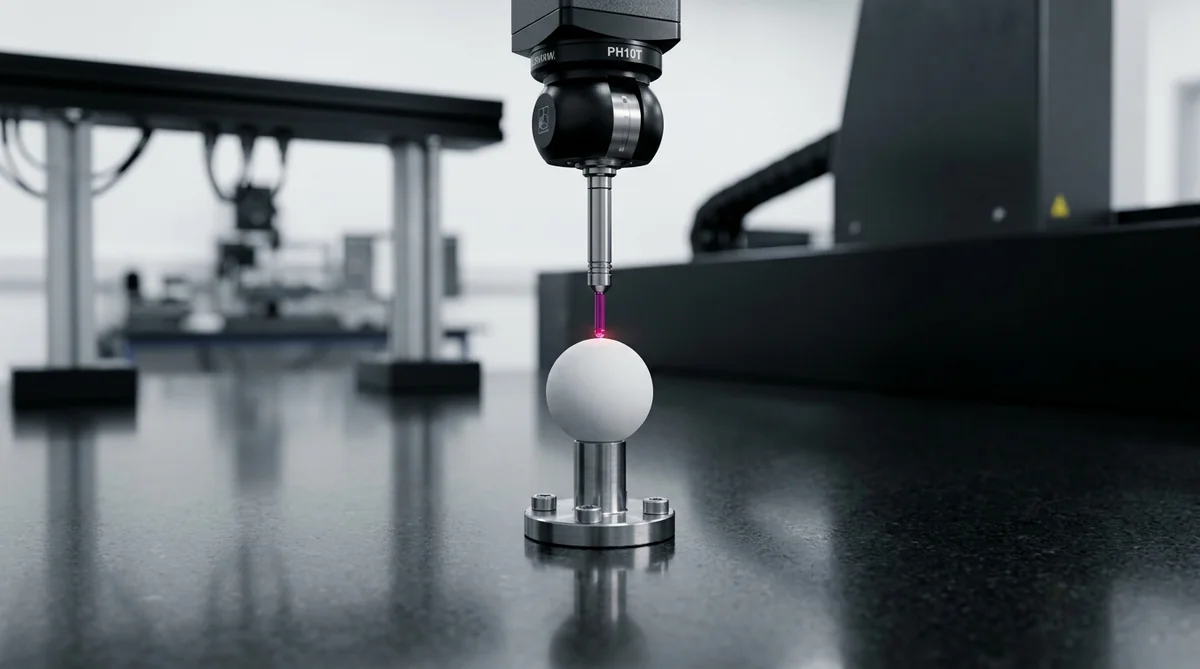
- Probe Qualification with Reference Calibration Spheres: Before executing inspection cycles, the CMM software runs an automated qualification routine against an ultra-precision ceramic reference sphere with verified sphericity (< 0.05 μm). Probing the sphere from multiple spatial angles calculates the exact effective radius and spatial center offsets of each ruby stylus ball, compensating for tip mechanical deflection and probe lobing.
- Traceability and ISO 10360-2 Calibration Compliance: Annual calibration follows ISO 10360-2 guidelines using calibrated step gauges and laser interferometers, ensuring national metrological traceability (NIST / CNAS).
Our High-precision bridge CMM laboratory maintains a constant 20.0°C (±0.5°C). For on-machine probing or fluctuating environments, continuous mathematical thermal compensation applies material-specific CTE scaling (e.g., 23.4 µm/m·K for 6061 aluminum) back to standard reference temperatures.
Tactile trigger probes capture discrete 3D points, suitable for basic prismatic geometry. High-speed continuous scanning sweeps thousands of data points across surfaces, capturing true form errors, roundness, cylindricity, and waviness.
Yes. When MMC is specified, the CMM calculates actual feature size versus virtual condition boundaries, mathematically allocating bonus tolerance to allowable positional deviation without compromising functional assembly.
high-precision machining & Full CMM Quality Documentation
At AS Prototypes, tight tolerances are not a marketing claim; they are an empirically validated guarantee. Every multi-axis CNC milled component, precision sheet metal assembly, or rapid injection molded housing is supported by verified quality infrastructure.
We provide comprehensive quality documentation tailored to your program requirements—including AS9102 First Article Inspection (FAI) reports, full CMM point-cloud verification logs, Material Test Reports (MTR) (MTC), and surface finish profilometer traces.