

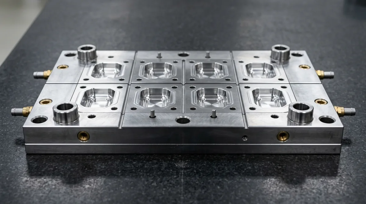
Tooling capital represents the single largest upfront capital commitment in commercial plastic manufacturing programs. Therefore, manufacturing engineers and procurement directors must evaluate injection mold life expectancy during early Design for Manufacturing (DFM) reviews to accurately forecast part unit costs and tooling amortization.
Maximizing tool longevity requires a holistic engineering approach balancing mold steel metallurgy, cavity erosion resistance, clamping mechanics, thermal cycling dynamics, and disciplined shop-floor preventative maintenance. An injection mold engineered for extreme longevity reliably delivers flash-free, dimensionally stable plastic components across hundreds of thousands or millions of high-speed clamping cycles.
At AS Prototypes, our in-house tooling facility integrates precision CNC machining and high-accuracy wire and sinker EDM to engineer production-ready molds. Whether you are launching low-volume bridge production or high-volume multi-cavity programs through our custom injection molding services, this technical whitepaper provides deep practical insights into SPI tooling classifications, mold steel metallurgy, wear mechanics, and lifecycle preservation.
- Core Focus & DFM Scope: Actionable shop-floor engineering guidelines for injection mold life expectancy, covering material selection, geometric tolerancing, and defect prevention.
- Dimensional Tolerance Baseline: General molded/cast features hold ISO 2768-mK or ±0.05 to ±0.10 mm (±0.002″ to ±0.004″); critical post-machined datum bores achieve ±0.010 mm (±0.0004″).
- Tooling & Surface Integrity: Cavity surfaces finished from SPI A-2 mirror polish (Ra 0.05 µm / 2 µin) to VDI 3400 spark-eroded textures with mandatory 1.0°–2.5° draft angle compensation.
- Metrology & Flow Validation: Pre-tooling DFM and rheological fill simulation paired with Zeiss CMM first-article inspection (FAI) and wall-thickness ultrasonic/section verification.
- Ex-Factory Turnaround: 7 to 12 business days for vacuum cast/urethane bridge batches; 18 to 35 business days for rapid aluminum/P20/H13 tooling and T1 sample delivery (excluding 3–5 days air transit).
SPI Tooling Classifications: Standards from Class 101 to Class 105
The Plastics Industry Association (formerly the Society of the Plastics Industry, or SPI) established five standardized mold classifications. These industry standards benchmark expected shot life, mold base construction, cavity steel hardness, ejection mechanisms, and cooling circuit complexity.
Selecting the correct SPI mold class eliminates two costly commercial pitfalls: premature tool degradation caused by under-specifying cavity steel, and unnecessary upfront tooling expenditure caused by over-engineering low-volume bridge tooling.
| SPI Mold Class | Rated Shot Life | Cavity & Core Steels | Minimum Hardness | Tooling Construction Criteria | Target Program Application |
|---|---|---|---|---|---|
| Class 101 | 1,000,000+ cycles | Hardened H13, S136, 420 Stainless, CPM 9V | 48 to 54 HRC | Hardened mold base (≥28 HRC), guided ejection, plated water lines, replaceable wear plates on slides. | High-speed medical consumables, caps, closures, automotive connectors. |
| Class 102 | Up to 1,000,000 cycles | Hardened H13, 420 SS, Pre-hardened 718H / P20 | 38 to 44 HRC | Steel mold base, guided ejection recommended, plated or stainless cooling circuits, slide wear plates. | Consumer electronics, appliance housings, industrial power tool chassis. |
| Class 103 | Up to 500,000 cycles | Pre-hardened P20, 2738, NAK80 | 28 to 36 HRC | Standard steel mold base (#2 or #3), conventional drilled cooling, standard ejector pin configuration. | Mid-volume production, commercial housings, non-abrasive polymer components. |
| Class 104 | Up to 100,000 cycles | Mild steel 1045, P20, or Aircraft Aluminum 7075-T6 | 150 HB (Al) / 28 HRC | Economical mold base, standard ejector plates, basic water channels without anti-corrosion plating. | Low-volume specialty devices, pilot validation lots, replacement spare parts. |
| Class 105 | Under 500 cycles | Aluminum 6061-T6, 7075-T6, or Master Unit Die (MUD) inserts | 95 to 150 HB | Modular MUD frame, hand-loaded cores or loose inserts, manual or simple hydraulic ejection. | Rapid prototype verification, clinical trial units, functional testing before steel cut. |
While SPI classifications provide a clear programmatic baseline, a tool’s physical operating lifespan in the press frequently deviates from these standard ratings. Actual cycle endurance is governed by tool steel selection, polymer abrasiveness, cooling design, and mechanical maintenance.
Tool Steel Metallurgy and Cavity Erosion Mechanics
In high-speed injection molding, tool steel surfaces endure severe localized mechanical, thermal, and chemical stresses. During each cycle, molten thermoplastic enters mold cavities under injection pressures ranging from 70 to 180 MPa, followed by aggressive clamping pressures that concentrate high tonnages across parting line shut-offs.
Four primary degradation mechanisms dictate tool wear over extended operational runs:
- Abrasive Cavity Wear: High-velocity polymer melt laden with reinforcing fibers scours gate orifices, runner transitions, and core pins. Over time, abrasive scouring washes out sharp shut-off corners and opens parting line tolerances, generating unsightly flash.
- Corrosive Outgas Attack: Halogenated flame retardants, PVC, POM (acetal), and fluoropolymers release acidic byproducts (such as hydrochloric and hydrofluoric acid vapors) during plastication. Unprotected mold steels suffer micro-pitting and surface etching that degrade optical finishes.
- Adhesive Galling: Moving tooling elements—including ejector pins, side-action slides, angle pins, and lifters—experience metal-to-metal contact. Without adequate surface hardness differentials, thermal expansion clearances, and lubrication, micro-welding and mechanical galling lead to catastrophic tool seizure.
- Thermal Fatigue (Heat Checking): Rapid cyclical temperature fluctuations between molten resin contact (up to 300°C) and chilled water cooling lines (15°C to 80°C) induce alternating tensile and compressive surface stresses, resulting in spiderweb micro-cracking across cavity faces.
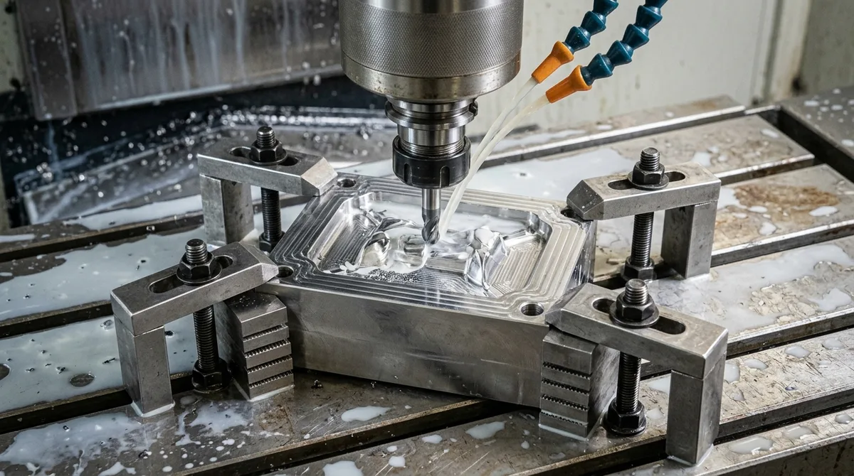
Selecting the appropriate mold alloy directly mitigates these wear vectors. Toolmakers evaluate five primary tooling alloys based on their metallurgical composition, achievable Rockwell hardness, thermal conductivity, and machinability:
| Tool Steel Grade | Alloy Type & Standards | Hardness Range | Corrosion Resistance | Wear Resistance | Polishability & Texture | Optimal Resin Suitability |
|---|---|---|---|---|---|---|
| S136 / AISI 420 | Martensitic Stainless (ESR) | 48 to 52 HRC | Exceptional | High | SPI A-1 / A-2 Optical Mirror | Optical PMMA, PC, corrosive PVC, fluoropolymers, medical cleanroom parts. |
| H13 / 1.2344 | Hot-Work Chromium Alloy | 48 to 52 HRC | Moderate | Exceptional | SPI B-1 / B-2 Fine Texture | Glass-filled nylon (PA66-GF), PEEK, PBT, PPS, high-temperature polymers. |
| P20+Ni / 1.2738 | Pre-hardened Chrome-Nickel | 28 to 34 HRC | Low to Moderate | Moderate | SPI B-2 / C-1 Satin Finish | Medium-volume ABS, PP, HDPE, PS consumer housings and structural bezels. |
| NAK80 Steel | Pre-hardened Age-Hardened | 37 to 43 HRC | Moderate | High | SPI A-2 High Gloss / Micro-EDM | Cosmetic enclosures, transparent consumer components, intricate EDM cores. |
| Aluminum 7075-T651 | Cold-Finished Aircraft Alloy | 150 HB (~80 HRB eq.) | High (Atmospheric) | Low | SPI B-1 to B-3 Semi-Gloss | Bridge tooling, pilot EVT/DVT batches, non-abrasive resins (PP, PE, TPE, ABS). |
For high-wear regions such as sub-gates, sprue bushings, and thin shut-off ribs, modular tooling design is best practice. Toolmakers embed hardened D2 tool steel (58 to 62 HRC) or tungsten carbide inserts directly into localized high-velocity flow paths, shielding the broader mold base from premature washout.
Resin Chemistry, Filler Dynamics, and Wear Acceleration
The chemical composition of the molded thermoplastic and its additive package drastically influence cavity wear rates. While unfilled commodity resins flow smoothly with minimal steel erosion, abrasive reinforced formulations can shorten unhardened tool life by a factor of ten.
Manufacturing teams must account for three primary resin-induced wear factors during the tooling specification phase:
- Glass Fiber and Mineral Fillers: Reinforced polymers such as PA66-GF30 (30% glass fiber) or PBT-GF40 contain microscopic glass needles that remain solid at processing temperatures (260°C to 310°C). As pressurized resin rushes through restricted gate orifices at velocities exceeding 50 m/s, these fibers gouge microscopic furrows in the steel matrix. A Class 103 P20 mold processing GF30 nylon may experience severe gate washout and out-of-tolerance flash after just 25,000 shots, whereas fully hardened H13 (50 HRC) easily sustains hundreds of thousands of cycles.
- Corrosive Decomposition by Flame Retardants: Flame retardant packages and halogenated polymers (such as PVC, PVDF, and halogenated ABS) release aggressive acidic vapors when exposed to elevated barrel temperatures and high shear rates. If condensation forms during cycle pauses, these vapors dissolve unprotected iron matrices within hours. Specifying electroslag remelted (ESR) S136 stainless steel or applying physical vapor deposition (PVD) titanium nitride (TiN) or nickel-phosphorus coatings provides an impervious barrier against acidic pit corrosion.
- Carbon Fiber Reinforcement: Carbon-filled resins (such as PEEK-CF30) possess higher tensile strength and stiffness than glass fibers. Although carbon fiber is somewhat less abrasive than glass fiber, the high melt temperatures and filler loading still erode mold gating transitions and core shut-offs. Cavity inserts intended for high-temperature carbon-filled polymers require vacuum heat-treated H13, CPM 9V, or solid cemented carbide inserts to resist premature mechanical degradation.
Understanding these resin dynamics allows toolmakers to formulate balanced material pairings: pairing abrasive engineering polymers with hardened tool steels and utilizing pre-hardened alloys or 7075 aluminum for benign commodity plastics.
Thermal Management, Cycle Fatigue, and Conformal Cooling
Thermal management is a critical yet frequently underestimated factor in injection mold longevity. Injection molding is fundamentally a thermodynamic heat exchange process. Every shot injects a mass of molten polymer at 200°C to 380°C into a cooled steel cavity maintained at 20°C to 120°C.
Uneven thermal dissipation produces localized thermal stress gradients across the mold plates. When a core pin or deep cavity rib runs significantly hotter than surrounding mold plates, differential thermal expansion exerts repetitive mechanical stresses. Over thousands of production hours, this cyclical expansion and contraction causes thermal fatigue micro-cracking, known on the shop floor as heat checking.
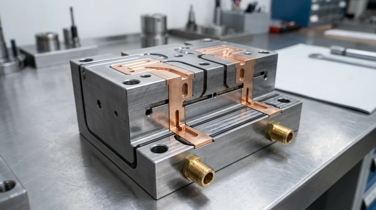
To eliminate localized hot spots and suppress thermal fatigue, toolmakers implement three high-performance thermal strategies:
- High-Conductivity Copper Alloy Inserts: Beryllium copper alloys (such as C17200 and MoldMAX) and copper-nickel-silicon alloys (Ampco 940) feature thermal conductivity ratings of 105 to 130 W/m·K for beryllium-copper grades (Ampco 940 is higher still), approximately three to five times higher than standard tool steels (25 to 35 W/m·K). Press-fitting copper alloy inserts into slender core pins or deep box-cavity cores rapidly draws heat into primary water cooling circuits, reducing localized thermal stress by up to 60%.
- Direct Metal Laser Sintering (DMLS) Conformal Cooling: Traditional gun-drilled cooling lines are constrained to straight, line-of-sight paths. For complex geometries, straight cooling lines leave deep bosses and curved surfaces under-cooled. Utilizing metal 3D printing (SLM / DMLS) in 1.2709 maraging steel allows toolmakers to grow curved, conformal cooling channels that closely trace part contours. Uniform heat extraction prevents differential part shrinkage, shortens cycle times by 15% to 35%, and mitigates cyclical thermal fatigue across cavity walls.
- Cooling Channel Corrosion Protection: Mineral scale deposits and rust inside untreated mold water circuits restrict flow velocity and degrade heat transfer efficiency. In Class 101 and 102 tools, all drilled water circuits should be electroless nickel plated or machined from corrosion-resistant 420 stainless steel to ensure uncompromised cooling performance across multi-year production campaigns.
Optimized thermal engineering preserves steel surface integrity, mitigates warping in finished plastic moldings, and extends mold life expectancy across demanding production schedules.
Parting Line Shut-Off Wear, Ejector Pin Galling, and Metrology
Mechanical wear on mold parting lines and moving components represents the most frequent cause of unscheduled tool downtime. In a high-speed injection press, mold halves close under clamping tonnages ranging from 50 to 1,000+ tons. Even minor misalignment or excessive clamping force will crush delicate shut-off faces.
Calculating proper clamping tonnage is essential to prevent parting line hobbing and coining. Clamping force is determined by multiplying total projected part area by resin cavity pressure:
Clamping Tonnage Equation:
Required Clamping Force (Tons) = Projected Area (cm²) × Cavity Injection Pressure (bar) × Safety Factor / 1,000
Where the engineering safety factor is typically set between 1.10 and 1.25. Over-clamping a mold beyond calculated tonnage crushes shut-off lands, inducing micro-cracks and coining that destroy the tool’s sealing ability.
Moving mold components must maintain precise running clearances to prevent flash penetration and mechanical binding. Ejector pins, stripper plates, and side-action slides require strict engineering tolerances:
- Ejector Pin Diametral Clearances: Standard pin-to-bore clearances must be held to 0.010 to 0.015 mm. For low-viscosity resins like nylon or polyethylene, clearances exceeding 0.020 mm permit resin intrusion into pin barrels, causing pin seizure and premature wear.
- Advanced Surface Coatings: Ejector pins and slides undergo surface nitriding to achieve 65 to 70 HRC case hardness. For high-speed Class 101 molds, applying Diamond-Like Carbon (DLC) or Physical Vapor Deposition (PVD) CrN coatings lowers the friction coefficient below 0.15, eliminating galling even during dry-cycle cleanroom operation.
- Guided Ejection Systems: Class 101 and 102 tools incorporate dedicated guide pillars and bronze bushings with self-lubricating graphite plugs to support ejector plates, ensuring parallel alignment and eliminating side-load deflection during high-speed return strokes.
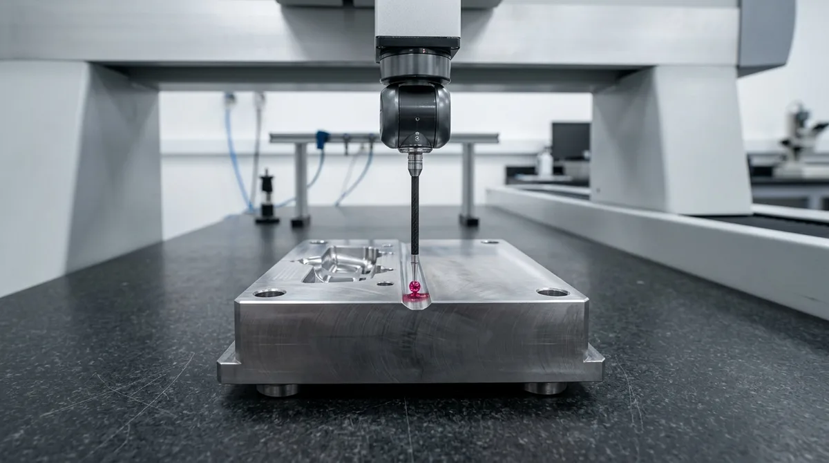
In our metrology laboratory, high-precision bridge Coordinate Measuring Machines (CMMs) equipped with ruby touch-trigger probes map shut-off flatness across cavity blocks to within ±0.005 mm. Catching parting line deviations, runner erosion, and cavity wear early enables micro-laser cladding restoration before steel surfaces experience irreversible damage.
Preventative Maintenance and Tooling Refurbishment Protocols
Implementing a structured, disciplined Preventative Maintenance (PM) protocol extends injection mold life expectancy by 35% to 50% compared to reactive maintenance. Rather than waiting for flashing or part pin-push damage, world-class molding facilities track shot cycles and execute multi-tiered servicing routines.
We organize mold lifecycle preservation into three structured operational tiers:
| Maintenance Level | Service Frequency | Operational Location | Key Inspection & Maintenance Tasks |
|---|---|---|---|
| Level 1: Operational | Every shift / 10,000 cycles | Press-side (In-machine) | Wipe down parting lines with lint-free solvent wipes. Inspect ejector pins and slides for dry running; apply food-grade or synthetic high-temp grease. Verify optical cavities for outgassing residue. Clear external water fitting leaks. |
| Level 2: Preventative | Every 25,000 to 50,000 cycles | Toolroom bench | Pull mold from press. Disassemble core and cavity plates. Perform ultrasonic bath cleaning of cavity inserts to clear micro-venting slots (0.015 to 0.025 mm deep). Replace worn Viton O-rings and water circuit baffles. Inspect slide wear plates and reset preloads. Apply anti-corrosion storage inhibitor. |
| Level 3: Major Overhaul | Every 250,000 to 500,000 cycles | Precision tooling facility | Complete tooling teardown. CMM dimensional verification against master CAD models. Replace complete ejector pin arrays and leader pin guide bushings. Micro-laser weld worn gate orifices and parting line coining. Wire EDM re-cutting or high-speed CNC re-machining of shut-offs. Re-polish optical surfaces to SPI A-1/A-2 standards. |
When parting lines or gate lands exhibit erosion, micro-laser deposition welding is the gold standard for mold restoration. By depositing microscopic beads of matching tool steel wire (e.g., H13 or S136 wire) with minimal heat input, technicians rebuild damaged shut-off edges with only a minimal heat-affected zone (HAZ) and negligible base metal distortion. Following micro-welding, precision CNC milling or sinker EDM restores blueprint tolerances to within ±0.010 mm, returning the mold to full operational specification.
Abrasive additives like glass fibers (e.g. PA66-GF30) and mineral fillers cause rapid abrasive wear at gate entries and parting lines. Corrosive polymers like PVC or POM release acidic outgassing that corrodes standard P20 steels, requiring fully hardened H13 (48-52 HRC) or stainless S136 tooling to maintain expected cycle life.
A Class 104 aluminum 7075-T6 mold typically yields 5,000 to 50,000 cycles when molding non-abrasive resins like polypropylene, polyethylene, or ABS under moderate clamping pressures. With proper parting line care and nickel plating, aluminum molds can occasionally exceed 100,000 parts.
Heat checking is thermal fatigue cracking caused by cyclical temperature swings between hot resin injection and chilled water cooling. It is prevented by utilizing high-toughness hot-work steels like H13, integrating high-conductivity beryllium copper inserts into hot spots, and employing conformal cooling channels.
Worn parting lines and washed-out gates are restored using precision micro-laser welding with matching tool steel filler wire. The minimal heat input avoids thermal distortion. Following welding, the geometry is restored to blueprint tolerances (±0.010 mm) via high-speed CNC hard milling or precision wire EDM.
Need Durable, High-Precision Injection Tooling?
AS Prototypes builds Class 101 to 105 injection molds with engineered shot longevity and tight part tolerances. Upload your 3D CAD models today for expert tooling DFM review and comprehensive manufacturing quotations within 24 hours.
Request Tooling DFM Review & Quote →






