

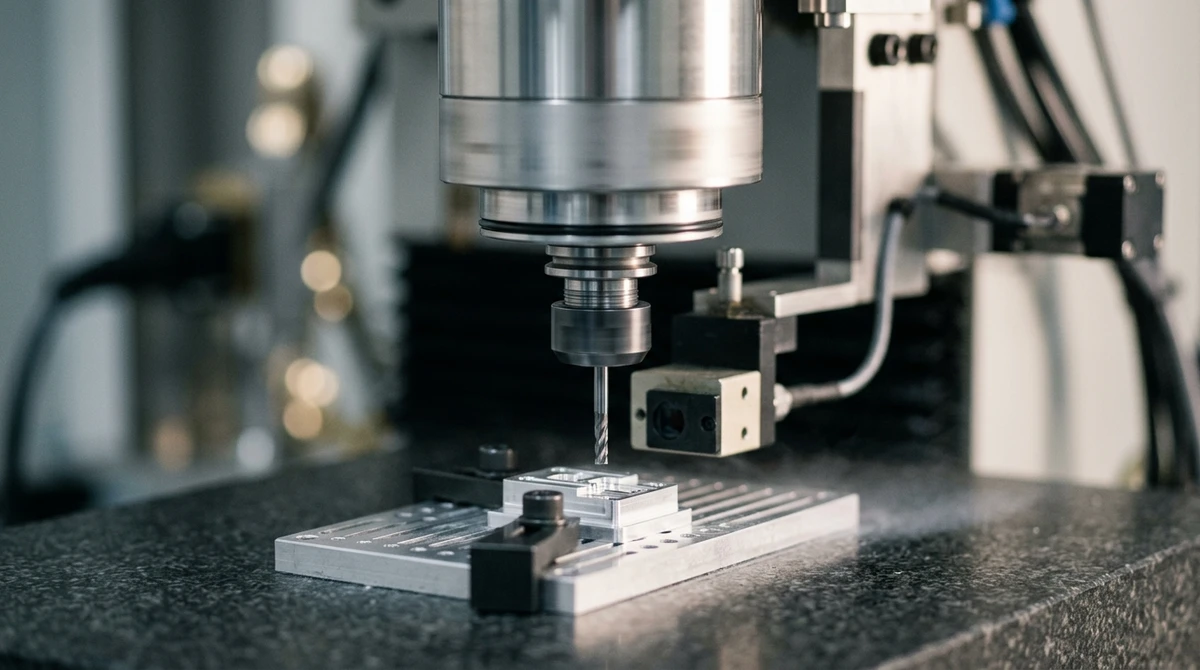
Across the frontiers of modern high-technology—including implantable biomedical devices, lab-on-a-chip diagnostic microfluidics, fiber-optic photonic transceivers, aerospace micro-propulsion, and semiconductor test sockets—product miniaturization has transitioned from an aspirational trend into an uncompromising functional mandate. While conventional precision CNC machining reliably achieves tolerances of ±0.010 mm (±10 μm) using cutting tools spanning 3.0 mm to 20.0 mm in diameter, micron-level component architectures demand an entirely distinct subtractive manufacturing paradigm: Micro-Milling (Micro-Machining).
Micro-milling is not merely “macro-machining scaled down.” When cutting tool diameters shrink to 0.05 mm to 1.0 mm (50 μm to 1,000 μm) and feature dimensions enter the micron regime, classical continuum mechanics break down. Machinists encounter the non-linear “Size Effect,” where the cutting edge radius rivals the uncut chip thickness, transforming the primary material removal mechanism from clean shear deformation into severe elastic-plastic plowing, micro-burr generation, and instant tool fracture. Mastering micro-milling requires an integrated manufacturing ecosystem comprising ultra-high-speed air-bearing spindles (up to 120,000 RPM), closed-loop machine kinematics with nanometer encoder feedback, ultrafine grain diamond and carbide tooling, and non-contact 3D optical profilometry. This engineering guide examines the cutting physics, tool deflection dynamics, machine tool architecture, metallurgical considerations, industrial applications, and metrology protocols essential for successful micro-scale prototyping.
Quick Engineering Takeaways (BLUF)
- The Size Effect & Minimum Chip Thickness (hmin): Micro-milling operates where uncut chip thickness approaches cutting edge radius (re ≈ 1.0 to 3.0 μm). If feed per tooth drops below hmin (20% to 35% of re), metal is plowed elastically and plastically rather than sheared, causing rapid work hardening, heavy Poisson burrs, and sudden tool fatigue.
- Extreme Sensitivity to Dynamic Spindle Runout: Total Indicated Runout (TIR) at the tool tip must remain ≤ 1.0 μm. At 80,000+ RPM, a runout of just 1.5 μm at fz = 1.0 μm/tooth makes one flute of a two-flute micro-cutter take ~88% of the cutting load (1.75 vs. 0.25 μm chip thickness) while the other rubs, triggering immediate tool breakage.
- Fourth-Power Tool Deflection Scaling (δ ∝ L3 / D4): Bending deflection increases inversely with the fourth power of tool diameter. A ∅0.2 mm endmill has 50,625× less structural rigidity than a standard ∅3.0 mm cutter; tool overhang must strictly adhere to L/D ≤ 3.
- Realistic Production Tolerances: While optical linear encoders resolve at 1 to 10 nanometers, practical micro-milling production tolerances are governed by thermal stabilization and tool wear, reliably yielding ±0.010 mm (±10 μm), with selected micro-features down to ±0.005 mm under cleanroom thermal control.
- Non-Contact Optical Metrology Mandate: Mechanical touch probes elastically deflect or scratch micron-scale features. Quality verification requires 3D laser scanning confocal microscopy and coherence scanning interferometry (WLI) to resolve sub-micron step heights and areal surface roughness (Sa < 0.05 μm).
Authored by the Senior Micro-Machining Engineering Team at AS Prototypes. Technical peer-review and metrology protocols audited by our In-House Metrology & Quality Engineering Department.
1. The Physics of Micro-Cutting: The “Size Effect” & Minimum Chip Thickness Mechanics
In conventional macro-milling, the uncut chip thickness (h) is orders of magnitude larger than the cutting edge radius (re) of the tool (h >> re). Under these macro conditions, workpiece materials can be treated as a continuous, isotropic continuum. Material removal occurs predominantly via steady shear plastic deformation along the primary shear plane, as described by classical Merchant orthogonal cutting mechanics:
φ = π / 4 – (β – α) / 2
where φ is the shear angle, β is the friction angle, and α is the tool rake angle. In macro-cutting, α is positive or slightly negative, promoting smooth chip curling and steady chip ejection.
In precision micro-milling, however, this foundational relationship is completely inverted. Because cutting tool diameters range from 0.05 mm to 1.0 mm, manufacturing limitations in tool grinding mean that the cutting edge radius cannot be scaled down proportionally. Even with focused ion beam (FIB) sharpening and ultra-fine diamond grinding wheels, a premium carbide micro-endmill possesses a cutting edge radius of re ≈ 1.0 to 3.0 μm. When operating at micro-feeds per tooth (fz ≈ 0.3 to 2.5 μm/tooth), the uncut chip thickness is on the same order of magnitude as—or even smaller than—the cutting edge radius (h ≤ re).
The Effective Negative Rake Angle & Stagnation Point
When h ≤ re, the cutting edge presents an effective rake angle (αeff) that is severely negative, often reaching -50° to -75° at the point of contact:
αeff = arcsin[(h – re) / re]
This steep negative geometry establishes a stagnation zone along the rounded edge radius. Material flowing above the stagnation point forms a genuine micro-chip, whereas material passing below the stagnation point undergoes severe compression, friction, and elastic-plastic plowing. The critical boundary separating these two behaviors is known as the Minimum Chip Thickness threshold (hmin):
hmin = re × (1 – cos θc)
where θc is the critical stagnation angle (typically between 30° and 55° depending on the material’s shear yield strength and friction coefficient). In practice, hmin corresponds to roughly 20% to 35% of the cutting edge radius:
- Elastic-Plastic Plowing Regime (h < hmin): If the programmed feed per tooth falls below hmin, zero chip formation occurs. The micro-tool edge simply rubs and elastically depresses the workpiece surface. As the tool passes, the material elastically springs back, while the subsurface suffers intensive plastic shearing. This plowing regime causes dramatic specific cutting energy spikes, severe work hardening in alloys like 316L stainless steel and titanium, rapid tool flank wear, and excessive Poisson burr formation along the top rims of micro-channels.
- Micro-Shearing Regime (h ≥ hmin): When the feed per tooth safely exceeds hmin, shear strain exceeds the material’s fracture strain limit, allowing genuine chip separation. Cutting forces stabilize, tool life improves dramatically, and burr formation diminishes.
Crystallographic Anisotropy & Grain Boundary Scattering
A second governing physical difference in micro-cutting is crystallographic heterogeneity. In macro-machining, the cutting tool engages millions of metallic grains simultaneously, so the workpiece behaves as an isotropic, homogeneous medium. In micro-milling, however, the depth of cut and feed per tooth are frequently smaller than the average metallurgical grain size (dgrain ≈ 10 to 50 μm in wrought 6061-T6 aluminum or C11000 copper).
Consequently, the micro-endmill does not machine bulk metal; it cuts through individual crystal grains. As the cutting edge crosses from one grain into an adjacent grain with a different crystallographic orientation, the resolved shear stress required to activate dislocation slip jumps discontinuously. This generates high-frequency cutting force oscillations, variable tool deflection, and micro-harmonic chatter that can fracture a fragile ∅0.2 mm tool within a fraction of a second if spindle dynamics and feed rates are not meticulously calibrated.
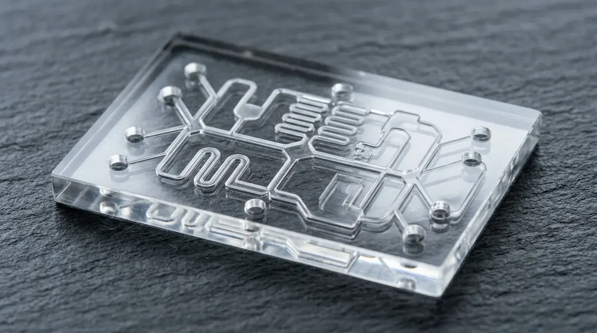
In micro-milling optical polymers (such as PMMA and cyclic olefin copolymer) and high-conductivity alloys, operating above the minimum chip thickness threshold prevents localized plastic plowing and guarantees optical clarity along serpentine fluidic micro-channels. Precision single-crystal diamond or polished micro-carbide endmills cut cleanly through the material, maintaining crisp 50 μm channel definition without thermal burrs or chip re-welding.
2. Micro-Tool Deflection, Dynamics & Runout Sensitivity
Because micro-cutting tools have microscopic cross-sections, structural mechanics dictate extreme vulnerability to lateral deflection and dynamic runout. Understanding tool stiffness formulas is critical for preventing catastrophic breakage during micro-milling cycles.
Fourth-Power Stiffness Scaling & Cantilever Deflection
Treating a micro-endmill as an elastic cantilever beam subjected to a concentrated radial cutting force (Fc) at its tip, the maximum deflection (δ) is governed by the Euler-Bernoulli beam equation:
δ = (Fc × L3) / (3 × E × I)
where L is the tool overhang length, E is the modulus of elasticity of the tool substrate (roughly 550 to 650 GPa for ultra-fine grain tungsten carbide), and I is the second moment of area of the circular shank cross-section:
I = (π × D4) / 64
Substituting I into the deflection formula reveals the governing relationship:
δ = (64 × Fc × L3) / (3 × π × E × D4) ∝ L3 / D4
This fourth-power inverse relationship is dramatic: reducing the cutter diameter from 1.0 mm to 0.2 mm at the same overhang length reduces the tool’s bending resistance by a factor of 625. If the aspect ratio increases even slightly, tool deflection escalates cubically with overhang length. For example, comparing a ∅0.2 mm endmill with an overhang of 0.6 mm (L/D = 3) to one with an overhang of 1.0 mm (L/D = 5) shows an increase in deflection by (1.0 / 0.6)3 ≈ 4.63× under identical cutting forces! Excessive deflection induces dimensional tapering in micro-slot sidewalls, gouging during cornering, and rapid flexural fatigue fracture.
Dynamic Spindle Runout (TIR) & Single-Flute Overloading
In standard macro-milling with a ∅10 mm cutter running at fz = 50 μm/tooth, a spindle runout of 3.0 μm represents only 6% of the tooth load, which is easily absorbed by the machine and workpiece. In micro-milling, however, dynamic runout is the number one cause of premature tool failure.
Consider a two-flute ∅0.2 mm micro-endmill running at a programmed feed of fz = 1.0 μm/tooth. If the total dynamic runout at the tool tip is measured at TIR = 1.5 μm, the actual instantaneous uncut chip thickness experienced by each flute becomes asymmetric:
fz1,eff = fz + (TIR / 2) = 1.0 + 0.75 = 1.75 μm
fz2,eff = fz – (TIR / 2) = 1.0 – 0.75 = 0.25 μm
Notice the catastrophic operational consequences:
- Flute 1 is overloaded by 75%, experiencing excessive bending stress that promotes instant fatigue failure.
- Flute 2 experiences an effective chip load of only 0.25 μm—falling well below the minimum chip thickness threshold (hmin ≈ 0.5 μm). Instead of cutting, Flute 2 rubs and plows, generating massive friction and workpiece burnishing.
- If dynamic runout exceeds 2.0 μm (TIR ≥ 2 × fz), Flute 2 cuts zero material entirely, transforming the two-flute tool into an unbalanced single-flute cutter operating under extreme cyclical shock.
For these reasons, our in-house micro-machining centers enforce a strict operational threshold: Dynamic Spindle Runout must remain ≤ 1.0 μm at full operating speed.
3. Machine Tool Architecture for High-Precision Micro-Milling
Attempting to execute micro-milling on a standard general-purpose vertical machining center (VMC) will invariably yield broken micro-tools, severe tool chatter, and out-of-spec parts. Micro-milling requires specialized ultra-precision machine kinematics engineered from the foundation up:
1. Ultra-High-Speed Spindles (UHSS) & Aerostatic Bearings
To achieve adequate surface cutting speeds (Vc = π × D × n / 1000) on miniature cutters, 5-axis and 3-axis micro-spindle rotational speeds must reach 60,000 to 120,000 RPM. For example, machining 6061-T6 aluminum with a ∅0.2 mm endmill at 80,000 RPM yields a modest cutting speed of Vc ≈ 50.3 m/min. At conventional 12,000 RPM spindle speeds, the cutting speed drops to an unacceptable 7.5 m/min, leading to built-up edge (BUE) formation and micro-tool snapping.
High-end micro-machining platforms utilize aerostatic (air-bearing) or hybrid ceramic-bearing spindles. Air-bearing spindles float the rotating shaft on a micron-thin cushion of pressurized air, eliminating mechanical ball contact, eliminating bearing vibration, and ensuring dynamic runout below 0.5 μm. Liquid-cooled jackets circulating chilled oil stabilized to ±0.1°C absorb spindle motor heat, preventing axial thermal growth from shifting the Z-datum during multi-hour micro-machining runs.
2. Mineral Polymer Granite Castings & Structural Damping
Because micro-cutting tools have virtually zero inherent damping capacity, ambient shop floor vibrations (from forklifts, sheet metal punches, or overhead cranes) and axis acceleration jerks can instantly shatter a ∅0.1 mm tool. Premium micro-machining centers feature solid mineral polymer granite machine bases. Polymer concrete provides an internal damping ratio 6× to 8× higher than traditional gray cast iron (FC30), rapid thermal equilibrium, and complete immunity to coolant corrosion.
3. Ironless Linear Direct Drives & Nanometer Optical Feedback
Traditional ball-screw drives suffer from mechanical backlash, stick-slip friction at microscopic feed steps, and elastic torsion during rapid direction reversals. Modern micro-mills utilize ironless linear direct-drive motors paired with non-contact optical linear encoders. These systems eliminate mechanical drive train components, delivering positional resolution down to 1 to 10 nanometers and eliminating quadrant glitches when interpolating 50 μm micro-circular radiused contours.
4. Micro-Tooling Metallurgy, Geometries & Advanced Coatings
Selecting micro-cutting tools requires balancing metallurgical hardness, transverse rupture strength, edge sharpness, and coating friction:
Sub-Micron Tungsten Carbide Substrates
Conventional carbide cutting tools utilize grain sizes of 1.0 to 3.0 μm. In a ∅0.2 mm micro-endmill, such large grains would result in cutting edges with serrated, jagged profiles where entire carbide grains pluck out during grinding. Precision micro-tooling utilizes ultrafine sub-micron tungsten carbide (WC) substrates with grain sizes of 0.2 to 0.4 μm, bound with 8% to 12% Cobalt. This metallurgy achieves extreme hardness (HV > 1,850) paired with superior transverse rupture strength (TRS > 4,500 MPa), allowing grinding wheels to produce continuous, razor-sharp cutting edges without micro-chipping.
Single-Crystal Diamond (SCD) vs. PCD Tooling
For non-ferrous alloys (OFHC copper, optical brass, aerospace aluminum) and optical polymers (PMMA, polycarbonate, cyclic olefin copolymer COC), Single-Crystal Diamond (SCD) monocrystalline tooling represents the pinnacle of micro-cutting. Monocrystalline diamond can be lapped to an edge radius of re < 20 nanometers—over 100 times sharper than polished tungsten carbide! SCD tools generate virtually zero cutting burrs and produce specular mirror finishes (Ra < 0.02 μm / 20 nm) directly from the machine tool, eliminating the need for manual polishing in optical light guides and microfluidic diagnostic chips.
Note: Diamond tools cannot be used on ferrous materials (stainless steels, carbon steels, nickel alloys) due to chemical graphitization and rapid carbon diffusion at cutting contact temperatures.
Ultrathin Nanocomposite PVD Coatings (< 0.8 μm)
In standard macro-machining, TiAlN or AlCrN PVD coatings are deposited with thicknesses of 3.0 to 5.0 μm to provide thermal and abrasive wear barriers. Applying a 4 μm coating to a micro-tool with a 1.5 μm edge radius would artificially round and blunt the cutting edge, increasing re to over 5 μm and plunging the cut squarely into the plowing regime. Micro-milling requires specialized ultrathin nanocomposite coatings (such as AlTiSiN or tetrahedral amorphous carbon ta-C DLC) with thicknesses controlled below 0.8 μm. These nanocoatings preserve knife-edge sharpness while providing oxidation resistance up to ~1,000°C (AlTiSiN) and, for ta-C, a coefficient of friction μ < 0.15 against non-ferrous metals.
Toolholding: Thermal Induction Shrink-Fit vs. Hydraulic Chucks
Standard ER collet chucks introduce 5 to 10 μm of runout—completely unacceptable for micro-tools. AS Prototypes utilizes thermal induction shrink-fit toolholders (Haimer Mini-Shrink) and high-precision hydraulic expansion chucks that guarantee dynamic runout ≤ 1.0 μm at 3× tool diameter overhang, ensuring maximum rotational balance at 100,000+ RPM.
5. Fluid Dynamics & Chip Evacuation: MQL vs. High-Velocity Gas Jet
In macro-machining, high-volume flood coolant (30 to 80 L/min) is the default standard for heat dissipation and chip flushing. In precision micro-milling, however, traditional flood coolant poses severe physical risks:
- Hydraulic Jet Tool Deflection: A pressurized flood coolant jet hitting a ∅0.15 mm micro-endmill exerts dynamic hydraulic drag forces sufficient to deflect or snap the fragile tool tip.
- Optical Fogging & Vision Blockage: Heavy coolant floods obscure the in-situ vision cameras and laser tool presetting sensors required to verify micro-cutter integrity between cycles.
- Thermal Shock & Chipping: In intermittent micro-milling, flood coolant rapidly quenches the micro-cutting zone, causing thermal fatigue cycling that leads to micro-flaking along the cutting edge.
To overcome these challenges, precision micro-milling relies on two primary fluid dynamic strategies:
- Minimum Quantity Lubrication (MQL): High-pressure micro-nozzles deliver an aerosol mist of high-lubricity biodegradable synthetic ester oil at consumption rates of only 10 to 50 mL/hour, propelled by dry compressed air or nitrogen gas at 0.4 to 0.6 MPa. The micro-droplets penetrate the stagnation cutting zone, reducing the tool-chip friction coefficient without exerting hydraulic tool-deflecting forces. MQL is exceptionally effective for micro-milling aluminum alloys, OFHC copper, and stainless steels.
- Vortex Cold Air Guns & Cryogenic Gas Delivery: When micro-machining thermoplastic polymers (such as PMMA, PEEK, Polycarbonate, and Cyclic Olefin Copolymer), chemical cutting fluids can cause solvent-induced environmental stress cracking (ESC) and optical hazing. We utilize vortex tube cold-air systems delivering dry chilled air at -10°C to -25°C. Chilled air removes cutting heat, raises the localized shear modulus of the plastic, prevents chip re-welding, and provides positive-pressure aerodynamic chip evacuation from deep micro-pockets.
6. Micro-Burr Formation Mechanisms & Suppression Strategies
Because micro-parts feature wall thicknesses and channel dimensions measured in tens of microns, post-process manual deburring with scalpels or abrasive brushes is virtually impossible—it risks snapping micro-fins or rounding precision edges. Burr suppression must be engineered directly into the CAM toolpaths and machining parameters.
Classifying Micro-Burrs
Micro-burrs form through three distinct metallurgical mechanisms:
- Poisson Burrs (Top Burrs): Generated when the rounded cutting edge plows material laterally as it traverses the cut, squeezing metal over the top edge of the slot or cavity wall. Highly prevalent in ductile metals (copper, pure aluminum) when h < hmin.
- Roll-Over Burrs (Exit Burrs): Formed when the cutting tool exits a workpiece edge. Instead of shearing off cleanly, the thin remaining chip undergoes bending deformation and rolls over the edge, creating a large, tenaciously attached burr along the exit boundary.
- Tear Burrs: Occur when micro-chips tear away from the workpiece along grain boundaries rather than shearing cleanly along the primary shear plane.
CAM Toolpath Strategies for Burr Elimination
- Continuous Down-Milling (Climb Milling): Climb milling ensures that the uncut chip thickness starts at its maximum value upon tooth entry and thins to zero at exit. This guarantees that initial contact occurs in the clean shearing regime (h > hmin), suppressing entrance burr formation.
- Exit Chamfer Toolpasses: Pre-chamfering or radiusing the exit boundaries of micro-channels prior to final slot clearing removes the thin wall section where roll-over burrs typically anchor, eliminating up to 90% of exit burrs.
- Trochoidal Micro-Milling: Circular trochoidal toolpaths maintain a constant radial tool engagement angle (≤ 30°), reducing instantaneous cutting force spikes and allowing higher chip loads per tooth that remain consistently above hmin.
- Sacrificial Backup Plates: When drilling micro-holes or milling through-slots in ductile foils or thin polymers, sandwiching the workpiece between sacrificial aluminum or PMMA backing plates prevents bottom roll-over burrs entirely.
7. Material-Specific Micro-Machinability Guide
Different engineering materials exhibit drastically contrasting physical behaviors when machined at the micron boundary. The table and detailed analysis below outline optimal parameters and CAM tactics for common micro-prototyping materials:
| Workpiece Material | Primary Micro-Cutting Challenge | Optimal Tooling Substrate & Geometry | Cutting Speed (Vc) & Feed (fz) | Coolant / Evacuation Mode |
|---|---|---|---|---|
| OFHC Copper (C10100) | Extreme ductility, severe plowing, high Poisson burr tendency | Single-Crystal Diamond (SCD) or ultra-polished 2-flute carbide | Vc: 80~160 m/min fz: 1.0~2.5 μm/tooth | MQL (Synthetic ester mist) + high-pressure micro-air blast |
| Aerospace Aluminum (6061-T6 / 7075-T651) | Built-up edge (BUE) formation, micro-flute chip packing | PCD or DLC-coated carbide (ta-C < 0.5 μm), high rake angle | Vc: 120~250 m/min fz: 1.5~3.5 μm/tooth | MQL aerosol or vortex cold air with alcohol trace |
| Titanium Ti-6Al-4V (Grade 5) | Low thermal conductivity (6.7 W/m·K), micro-notch wear, rapid tool snapping | Sub-micron carbide + AlTiSiN nanocoating (≤ 0.8 μm), 4-flute corner radius | Vc: 35~65 m/min fz: 0.6~1.5 μm/tooth | MQL with high-pressure nitrogen gas assist |
| Austenitic Stainless (316L / 17-4PH) | Intense work-hardening when h < hmin, severe abrasive wear | Solid sub-micron carbide, AlCrSiN coating, reinforced core diameter | Vc: 40~75 m/min fz: 0.8~1.8 μm/tooth | High-lubricity MQL mist + micro-blast chip clearing |
| Optical PMMA & Polycarbonate (PC) | Low glass transition temp (Tg), chip melting & optical hazing | Single-Crystal Diamond (SCD), single-flute polished upcut geometry | Vc: 150~350 m/min fz: 2.0~5.0 μm/tooth | Vortex cold air gun (-15°C to -20°C), strictly zero cutting fluid |
| Engineering Polymers (PEEK / Torlon / Vespel) | Elastic deformation during cutting, hole taper in high-aspect micro-drilling | Ultra-sharp uncoated carbide or diamond, double-margin micro-drills | Vc: 80~180 m/min fz: 1.2~3.0 μm/tooth | Chilled air blast with active vacuum dust shroud |
8. High-Impact Industrial Applications: Precision Prototyping in Action
Micro-milling bridges the technological gap between macro CNC milling and photolithographic silicon MEMS etching. While silicon cleanroom etching is restricted to planar 2.5D geometries in brittle substrates, precision micro-milling creates complex 3D freeform surfaces in engineering-grade metals, alloys, and optical thermoplastics across mission-critical industries:
1. Biomedical Diagnostics & Lab-on-a-Chip Microfluidics
Point-of-care diagnostic chips, DNA electrophoresis cartridges, and digital droplet PCR platforms demand intricate micro-channel networks spanning widths of 50 μm to 150 μm and depths of 50 μm to 250 μm. Unlike injection molding—which requires weeks of tooling lead time and expensive mold inserts—direct micro-milling enables agile rapid prototyping of microfluidic devices in optical-grade PMMA, polycarbonate, cyclic olefin copolymer (COC), and Grade 23 Ti-6Al-4V ELI. Single-crystal diamond micro-endmills machine optical detection windows with specular clarity (Ra < 0.02 μm), eliminating laser signal scattering during fluorescence detection.
2. Semiconductor ATE Test Sockets & Fine-Pitch Guide Plates
Automated test equipment (ATE) for high-density BGA packages, microprocessors, and RF power modules requires custom IC test sockets and probe guide plates drilled with thousands of high-aspect micro-holes. In our specialized semiconductor machining division, we routinely produce test sockets in high-performance dielectric polymers (Torlon 4203, Vespel SP-1, Semitron, PEEK) featuring ∅0.10 mm to ∅0.25 mm holes with at least a 0.10 mm web between neighboring holes (e.g., ∅0.10 mm on 0.20 mm pitch). Using custom double-margin solid carbide micro-drills spinning at 100,000 RPM, hole true position is held within ±0.010 mm across large array areas without thermal hole taper or drill drift.
3. High-Flux Micro-Pin Fin Cold Plates & Thermal Management
Next-generation aerospace avionics, GaN radar power amplifiers, and AI accelerator chips generate concentrated heat fluxes exceeding 500 W/cm². Direct micro-milling of oxygen-free high-conductivity copper (OFHC C10100) micro-channel cold plates and micro-pin fin arrays (pin cross-sections: 120 μm × 120 μm with heights up to 500 μm) dramatically increases fluid-wetted surface area while minimizing boundary layer thermal resistance. Precision high-speed micro-milling ensures square pin cross-sections without rounding or lateral deflection.
4. Photonic Alignment Blocks & Fiber-Optic V-Grooves
Fiber-optic transceivers, multiplexers, and photonic integrated circuits (PICs) rely on micro-machined silicon, Invar, or brass alignment blocks featuring high-precision V-grooves and alignment stops. Angular accuracy within ±0.02° and groove depth tolerances of ±0.005 mm provide the passive pre-alignment datums between single-mode fiber arrays (core diameter: 9 μm) and laser diode emitters; final sub-micron coupling is still achieved by active alignment.
5. Miniature Aerospace Mechanisms & Precision Horology
Micro-turbines, miniature planetary gearboxes (module m < 0.1 mm), satellite cold-gas thruster micro-nozzles, and surgical robotic wrist linkages require high-strength titanium, MP35N, or 17-4PH stainless steel components machined to tight geometric tolerances (±0.010 mm). Micro-milling delivers true 3D involute gear tooth profiles with mirror surface finishes that minimize friction and gear backlash in miniature actuator drives.

9. Metrology & Quality Verification at the Micron Boundary
Verifying micro-machined prototypes introduces profound metrological challenges. Conventional coordinate measuring machines (CMMs) equipped with ruby touch-trigger probes fail at this scale: even a miniature ∅0.3 mm stylus is larger than many microfluidic channels, and the 0.05 N to 0.1 N mechanical probing force can elastically deflect thin walls or scratch optical surfaces. Quality assurance for micro-milling mandates non-contact 3D optical and electron metrology:
1. 3D Laser Scanning Confocal Microscopy (Keyence VK-X / Olympus LEXT)
Confocal microscopy directs a focused laser beam through a pinhole aperture, detecting only light reflected precisely from the focal plane. By translating the focal plane along the Z-axis, the system captures a stack of optical slices and reconstructs a high-density 3D topographical map with Z-axis height resolution down to 0.5 nanometers. Confocal metrology directly measures micro-channel depths, wall draft angles, corner radii, and critical dimensional steps without physical contact.
2. Coherence Scanning White Light Interferometry (WLI / CSI)
For optical components, micro-mirror arrays, and diamond-milled surfaces, Coherence Scanning Interferometry splits a white light beam into a reference beam and an inspection beam. The resulting optical interference fringe patterns map areal surface texture per ISO 25178, quantifying arithmetical mean height (Sa), root-mean-square height (Sq), and maximum height (Sz) down to sub-nanometer repeatability (Sa < 0.02 μm).
3. Focus Variation Optical Metrology
Focus variation combines small depth of field with continuous vertical scanning to capture both geometric shape and true-color texture data. Unlike standard interferometry, focus variation successfully measures steep surface flanks up to 85°, making it the ideal protocol for evaluating high-aspect micro-pin fin heat sinks and miniature gear tooth profiles.
4. High-Magnification Optical Video Measuring Microscopy (VMS)
For implantable biomedical titanium components and semiconductor test sockets, High-magnification optical video microscopy (50× to 200× zoom) verifies cutting edge integrity, confirms complete absence of micro-burrs, and detects any localized micro-cracking or grain boundary tearing.
10. DFM Guidelines for Micro-Milled Components
Designing components for micro-milling requires balancing functional miniature geometry against the physical realities of tool deflection, minimum corner radii, and chip evacuation limits. Applying structured design for manufacturing (DFM) principles during the CAD stage prevents costly tool breakage and ensures prototype success:
| Design Feature | Standard Manufacturing Limit | High-Precision Micro Tier | DFM Engineering Rationale |
|---|---|---|---|
| Aspect Ratio (Depth-to-Width) | L/D ≤ 3:1 | L/D ≤ 5:1 (with step-down CAM) | Aspect ratios > 5:1 cause steeply rising (∝ L3) tool deflection and chatter; require EDM if deeper. |
| Minimum Internal Corner Radius | R ≥ 0.15 mm (∅0.3 mm tool) | R ≥ 0.05 mm (∅0.1 mm tool) | Sharp 90° internal corners cannot be milled; specify corner radius > tool radius by 15% to avoid tool engagement spikes. |
| Minimum Wall Thickness | 0.10 mm (100 μm) | 0.03 mm to 0.05 mm (30~50 μm) | Supported walls resist deflection; unsupported tall micro-fins bend under lateral cutting pressures. |
| Micro-Hole Minimum Diameter | ∅0.20 mm | ∅0.08 mm to ∅0.10 mm | Requires peck drilling cycles with complete flute retraction and high-pressure gas flushing. |
| Floor Flatness & Step Transitions | Flat bottom with 0.05 mm radius | Ball-nose or toroidal blend radius | Flat-end micro-cutters have zero center cutting velocity; specify slight corner chamfer or radius for cleaner floor finishes. |
11. Comprehensive Comparison: Macro-Milling vs. Precision Micro-Milling
The following engineering matrix highlights the technical, physical, kinematic, and operational contrasts between standard macro-milling and precision micro-milling at AS Prototypes:
| Technical Parameter | Conventional Precision Macro-Milling | Ultra-Precision Micro-Milling Tier | Engineering Implication & Process Control |
|---|---|---|---|
| Cutting Tool Diameter (D) | 3.0 mm to 25.0+ mm | 0.05 mm to 1.0 mm (50 μm to 1,000 μm) | Tool rigidity scales with D4; micro-tools deflect easily under lateral cutting forces. |
| Spindle Operating Speed | 8,000 to 24,000 RPM | 60,000 to 120,000 RPM | Ultra-high speed required to maintain minimum surface cutting velocity (Vc) on micron-level tools. |
| Dynamic Spindle Runout (TIR) | 3.0 μm to 8.0 μm at nose | ≤ 1.0 μm at operating RPM | Runout > 1.0 μm causes single-flute overloading, cyclical chatter, and instantaneous micro-tool breakage. |
| Primary Material Removal Mode | Pure shear plastic deformation (h >> re) | Elastic-plastic plowing, rubbing & micro-shear (h ≤ re) | Feed per tooth must exceed minimum chip thickness (hmin) to avoid severe work hardening and burr formation. |
| Dimensional Tolerance Band | ±0.010 mm to ±0.050 mm | ±0.010 mm (±10 μm); ±0.005 mm on selected features | Requires thermal enclosure stabilization (±0.2°C), nanometer encoder feedback, and laser tool length presetting. |
| Surface Roughness (Ra) | Ra 0.8 μm to 3.2 μm | Ra 0.02 μm to 0.10 μm (Optical Quality) | Single-crystal diamond tools generate mirror optical surfaces directly from the machine without manual polishing. |
| Coolant & Chip Evacuation | High-volume flood coolant (30~80 L/min) | Minimum Quantity Lubrication (MQL) + Vortex Cold Air | Heavy flood coolant jets exert dynamic hydraulic pressure that can physically bend fragile 0.1 mm micro-cutters. |
| Primary Metrology Method | Contact touch-trigger CMM (∅1~3 mm styli) | 3D Laser Confocal Microscopy & WLI Interferometry | Touch styli are too large to enter micro-cavities and elastically deflect thin walls; non-contact optical scanning is mandatory. |
For micro-endmills with diameters between 0.05 mm and 0.5 mm, total dynamic spindle runout (TIR) must remain strictly below 1.0 μm at full operating speed. Dynamic runout exceeding 1.0 μm causes severe tooth load asymmetry: one flute takes double the programmed chip load while the opposite flute purely rubs and plows, inducing cyclical bending shocks and instantaneous tool breakage.
Ultra-precision micro-machining centers mitigate thermal drift through a three-tier thermal stabilization architecture: solid mineral polymer granite machine bases with high thermal inertia, continuous chilled oil jacket circulation around the spindle cartridge (±0.1°C), and fully enclosed climate-controlled machine enclosures (20.0°C ±0.2°C) combined with direct nanometer optical glass scale feedback.
Minimum chip thickness (hmin) is the critical threshold of uncut chip thickness below which a cutting tool cannot shear metal into a chip. Because micro-tool cutting edge radius (re ≈ 1–3 μm) is on the same scale as the feed per tooth, operating below hmin (typically 20% to 35% of re) forces the tool to elastically compress and plastically plow the material. This creates severe friction, rapid work hardening in stainless steels and titanium, heavy Poisson burr formation, and accelerated tool wear.
High-volume flood coolant is avoided because the dynamic hydraulic pressure from a 30 to 80 L/min coolant jet exerts lateral drag forces sufficient to elastically deflect or snap fragile micro-cutters under 0.3 mm in diameter. Furthermore, flood coolant causes thermal shock cycling in intermittent micro-milling and obscures high-resolution vision systems. Instead, micro-milling utilizes Minimum Quantity Lubrication (MQL) aerosol mist or vortex chilled air (-15°C) to evacuate chips and lubricate the contact zone.
While modern linear direct drives and optical encoders boast 1 to 10 nanometer feedback resolution, practical production tolerances on micro-milled parts are governed by thermal equilibrium, tool wear, and material springback. AS Prototypes reliably achieves dimensional tolerances of ±0.010 mm (±10 μm) across production batches, with selected optical features held down to ±0.005 mm under tight cleanroom climate control.
Accelerate Your Miniature Hardware with AS Prototypes Micro-Machining
Developing breakthrough miniature medical devices, diagnostic microfluidic chips, optical guides, or aerospace micro-components demands manufacturing capabilities far beyond standard machine shops. At AS Prototypes, our in-house precision micro-machining facility features multi-axis micro-milling centers equipped with 100,000+ RPM aerostatic spindles, mineral-cast vibration-damped machine beds, and non-contact 3D confocal optical metrology.
Whether your application requires titanium micro-components, PEEK test sockets with high-density micro-holes, or optical polymers with mirror finishes, our engineering team provides comprehensive CAD DFM reviews within 24 hours, rapid prototype tooling turnarounds, and full optical metrology inspection reports.







