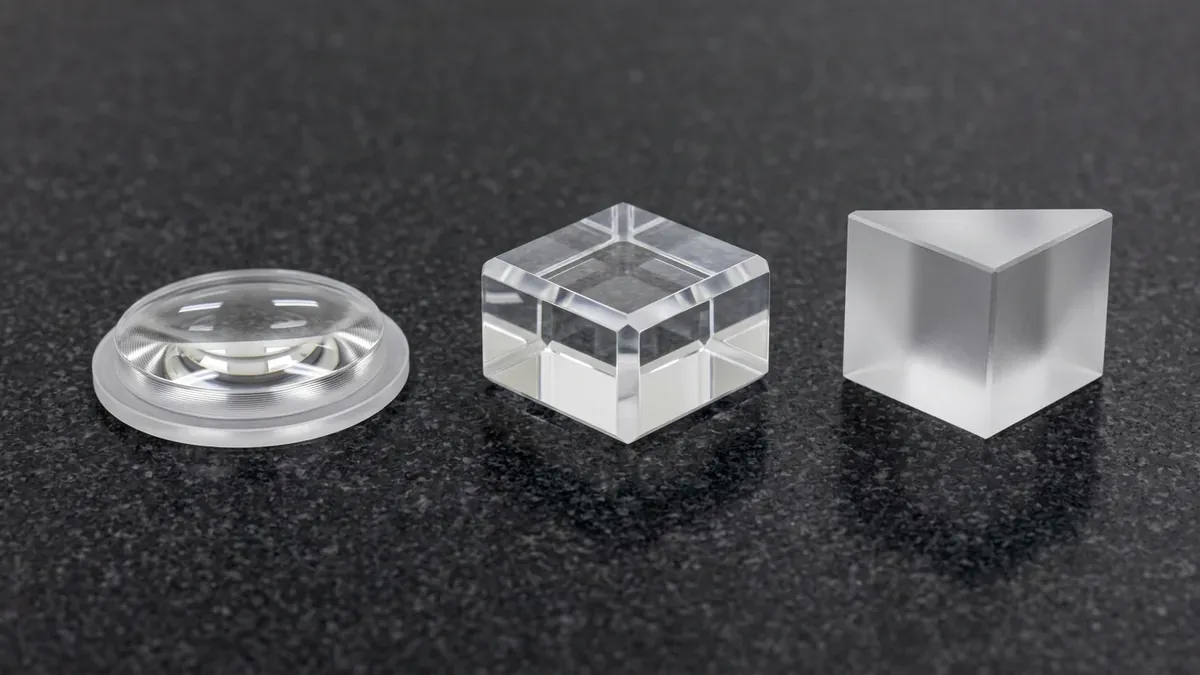
In high-tech industries ranging from automotive LiDAR illuminators and HUD projection prisms to biomedical microfluidic chips and endoscopic diagnostic optics, demand for optical-grade surface finish in plastic machining has surged exponentially. Unlike opaque mechanical engineering plastics where micro-machining cusp marks and residual tool marks are cosmetically acceptable, transparent optical components operate under the strict physics of wave optics: every micron-scale ripple, microscopic scratch, or internal stress fringe directly induces ray scattering, severe optical distortion, astigmatic blur, and chromatic aberration.
Achieving true optical clarity (Ra 0.02–0.05 μm, total light transmittance > 92% on PMMA, and haze < 0.5%) on polymers is an unforgiving manufacturing challenge.
At AS Prototypes, we bridge the gap between rough CNC milling and optical physics by combining Single Point Diamond Machining (SPDT), temperature-controlled multi-axis diamond fly cutting, thermal stress-relieved vapor polishing (for PC), progressive micromesh diamond buffing (for PMMA), and non-contact 2.5D optical vision measurement (VMS) paired with sacrificial-coupon profilometry. Below, our precision optics engineering team provides an in-depth technical analysis of materials, diamond tooling dynamics, post-polishing protocols, and quality verification standards.
- 1. The Physics of Optical Plastic Machining: Why Polymers Behave Differently
- 2. Ultra-Precision CNC Machining Strategies: Single-Crystal Diamond Tooling
- 3. Advanced Optical Post-Processing & Polishing Technologies
- 4. Engineering Comparison: Optical Plastic Materials Matrix
- 5. Metrology & Quality Inspection for Optical-Grade Plastics
- 6. Technical Engineering FAQ
1. The Physics of Optical Plastic Machining: Why Polymers Behave Differently
Machining optical plastics differs fundamentally from precision metal cutting due to the viscoelastic, thermal, and molecular characteristics of amorphous optical polymers:
- Low Glass Transition Temperatures (Tg): Optical acrylic (PMMA) softens at approximately 105°C, while optical polycarbonate (PC) softens near 145°C. The thermal conductivity of polymers is extraordinarily poor (k ≈ 0.19–0.22 W/m · K, roughly 1/1000th that of aluminum). Consequently, 90% of the cutting heat remains trapped directly at the tool-workpiece shear interface. Without precise high-speed chip evacuation, localized frictional heat instantaneously micro-melts the surface, causing microscopic tearing, smeared polymer gumming, and severe optical surface whitening.
- High Viscoelasticity & Micro-Vibration Amplification: Due to a low Young’s modulus (E ≈ 2.4–3.2 GPa), optical plastics flex elastically under cutting pressure. Any tool imbalance, spindle bearing micro-runout, or cutter deflection manifests as micro-ripples across the finished surface. When focused light transmits through these ripples, it behaves as a parasitic diffraction grating, destroying optical focal precision.
- Photoelastic Sensitivity & Residual Stress Birefringence: Excessive mechanical clamping pressure or aggressive toolpath plunge rates introduce severe internal residual stresses into the amorphous polymer matrix. Under polarized illumination, these unrelaxed stresses cause optical birefringence (double refraction), creating severe phase distortion in laser optics, polarization beam splitters, and biomedical diagnostic sensors.
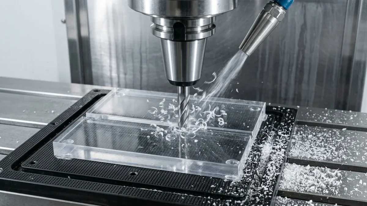
2. Ultra-Precision CNC Machining Strategies: Single-Crystal Diamond Tooling
Achieving optical finishes directly on the CNC machine tool requires transitioning from conventional chip shear to ductile-mode micro-shearing:
1. Monocrystalline Diamond (MCD) & SPDT Tooling
While standard carbide end mills feature cutting edge hone radii (rn) of 5 to 10 μm, single-crystal natural or synthetic monocrystalline diamond (MCD) tools feature ultra-sharp lapped cutting edges (rn < 0.05 μm). Furthermore, diamond possesses the highest thermal conductivity of any known solid (> 2,000 W/m · K) and near-zero chemical affinity to optical polymers, completely eliminating built-up edge (BUE) and polymer gumming.
2. High-Speed Dynamically Balanced Spindles & Diamond Fly Cutting (DFC)
For planar light guides, solar concentrators, and optical prisms, AS Prototypes utilizes high-speed diamond fly cutting mounted on dynamically balanced CNC spindles rotating at 15,000 to 24,000 RPM. Precision ceramic hybrid spindle bearings minimize mechanical waviness and runout. The single-crystal diamond tool sweeps across the workpiece in a continuous fly-cut trajectory, producing surface roughness as fine as Ra 0.02 to 0.05 μm (20 to 50 nm) directly off the machine on cell-cast PMMA.
3. Toolpath Kinematics & Depth-of-Cut Control
- Strict Climb Milling (Down-Milling): Up-milling rubs the polymer before the chip forms, causing severe plastic smearing and localized whitening. Climb milling initiates cutting at maximum chip thickness and tapers to zero, cleanly shearing polymer chains.
- Superfinishing Depths: Roughing cycles clear bulk stock, followed by multi-stage semi-finishing (Ap = 0.05 mm). The final optical superfinishing pass removes merely 0.008 to 0.015 mm of stock at optimized chip loads (Fz = 0.01–0.03 mm/tooth), ensuring purely elastic-plastic shear transitions.
- Cooling & Chip Evacuation: Pure dry compressed air chilled to -10°C via vortex tubes or alcohol-free chilled deionized (DI) water micro-mist is applied continuously. Warning: Standard petroleum-based cutting oils and alcohol-containing coolants must never be used on optical PMMA or PC, as aromatic hydrocarbons and alcohols cause immediate environmental stress cracking (ESC) and crazing.
3. Advanced Optical Post-Processing & Polishing Technologies
For complex 3D freeform lenses, concave spherical reflectors, and intricate internal light guide pipes, post-machining optical polishing is required to transform microscopic milling cusps into continuous optical glass clarity:
1. Chemical Vapor Polishing (Polycarbonate & ABS Only — Never PMMA)
Vapor polishing is the gold-standard technique for restoring crystal transparency to machined Polycarbonate (PC) (and smoothing ABS), whereas acrylic (PMMA) must never be exposed to solvent vapors to avoid hazing and micro-crazing:
- Chemical Mechanism: The component is suspended inside a climate-controlled containment chamber where heated solvent vapor (typically high-purity dichloromethane or Weld-On 4 vapor) condenses evenly across the cold plastic surface. The solvent vapor temporarily dissolves the outermost 1 to 2 μm polymer skin. Surface tension immediately flattens microscopic tool marks into a perfectly smooth liquid layer. As the solvent flashes off under vacuum, the polymer re-solidifies with pristine optical clarity.
- The Mandatory Pre- and Post-Vapor Annealing Cycle: Subjecting unannealed, stressed machined PC parts to solvent vapor triggers violent micro-crazing and stress cracking. At AS Prototypes, every machined polycarbonate part undergoes a controlled thermal stress-relief annealing cycle at 60°C to 80°C (for 2 to 4 hours followed by slow oven cooling at ≤ 10°C/hr) before and after entering the vapor chamber, preventing solvent stress cracking without thermally warping tight-tolerance features.
2. Multi-Stage Diamond Slurry Mechanical Polishing
For high-precision imaging optics and aspheric lenses where vapor polishing might induce unacceptable edge rounding or geometric form error, automated mechanical optical lapping is deployed:
- Progressive Wet Sanding: Precision waterproof micro-finishing films graded from #1000 → #2000 → #3000 → #5000 grit under constant deionized water rinse, systematically eliminating previous step scratches.
- Colloidal Diamond & Alumina Buffing: High-speed flannel wheels and soft optical pitch laps saturated with 0.5 μm polycrystalline diamond suspension, followed by sub-micron aluminum oxide / cerium oxide polishing slurry, restoring mirror clarity (Ra 0.02–0.05 μm) on cell-cast PMMA.
3. Hydrogen-Oxygen Flame Polishing (PMMA Only)
For clear cast acrylic (PMMA) display edges, light pipe peripheries, and thick architectural prototypes, a micro-torch powered by an electrolytic hydrogen-oxygen generator is swept across the edge at high speed. The localized clean flame micro-melts the PMMA surface instantly. Note: Flame polishing is strictly restricted to PMMA; attempting to flame-polish Polycarbonate results in carbonization, burning, and yellow discoloration.
4. Engineering Comparison: Optical Plastic Materials Matrix
Selecting the optimal transparent polymer requires balancing refractive performance, thermal resistance, machinability, and post-polishing behavior:
5. Metrology & Quality Inspection for Optical-Grade Plastics
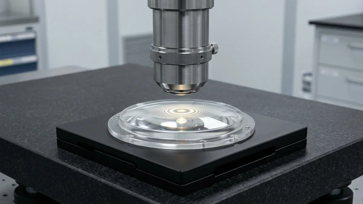
Quantifying optical surface quality requires non-contact, high-magnification metrology conforming to ISO 10110 (Optics and photonics standards):
1. Non-Contact 2.5D Optical Vision Inspection & Sacrificial Witness-Coupon Profilometry
Because direct diamond-stylus tracing can mar soft optical polymers on active clear apertures, our metrology laboratory pairs non-contact 2.5D optical vision measurement systems (VMS, 50×–200× magnification) with calibrated ISO 4287 stylus profilometry performed on co-machined sacrificial witness coupons, verifying optical surface roughness down to Ra 0.02–0.05 μm without touching the functional lens face.
2. Spectrophotometric Transmittance & Haze Measurement
Per ASTM D1003, optical clarity is quantified across the visible spectrum (380 nm to 780 nm) using an integrating sphere spectrophotometer. We verify that total hemispherical transmittance exceeds 92.0% for PMMA and COP, while diffuse light scattering (Haze) is verified below 0.5%.
3. Circular Polariscope Stress Birefringence Testing
To ensure that optical plastic components perform without optical distortion or double refraction under dynamic operating conditions, finished parts are inspected between crossed circular polarizers. Any latent internal stresses appear as visible colored isochromatic fringe patterns, allowing our quality engineers to verify complete stress relaxation before delivery.
6. Technical Engineering FAQ
Yes, but it requires chemical vapor polishing. Direct off-the-machine diamond turning on PMMA produces immediate mirror-like transparency (Ra 0.02–0.04 μm), whereas PC forms ductile chips that leave a faint translucent haze. Following specialized 60–80°C thermal annealing and solvent vapor polishing, PC reaches full glass-like transparency with > 89% light transmittance and superior impact resistance.
Conventional CNC milling relies on multi-flute carbide end mills, yielding surface roughness around Ra 0.4–1.6 μm with visible tool marks. Single-point diamond machining uses monocrystalline diamond (MCD) tools on high-speed dynamically balanced spindles, achieving optical mirror finishes (Ra 0.02–0.05 μm) directly off the machine on cell-cast PMMA without manual abrasive marks.
CNC machining introduces localized shear stresses into the outer layers of the polycarbonate workpiece. If exposed to dichloromethane solvent vapors without prior stress relief, the solvent penetrates stress concentration lines, triggering immediate micro-crazing and catastrophic structural cracking. Thermal stress-relief annealing at 60°C to 80°C relaxes polymer chains without warping tight dimensions, ensuring a pristine, craze-free optical gloss.
Cyclic Olefin Copolymers (COC / COP, such as Zeonex or Topas) and PMMA (acrylic) exhibit near-zero photoelastic sensitivity, making them the premier choices for polarized light systems, biomedical diagnostic optical discs, and laser sensors. Polycarbonate has high photoelastic sensitivity and must be carefully stress-annealed if used in polarization-sensitive setups.
Optical transmission demands surface roughness Ra 0.02 to 0.05 μm. Precision diamond flycutting/turning or progressive micromesh buffing (for PMMA) and vapor polishing (for PC) eliminate scattering micro-grooves to achieve >89%–92% clarity.
Achieve Verified Optical Clarity on Custom CNC Machined Plastic Parts
Eliminate tool cusp scattering, residual stress birefringence, and solvent crazing with our in-house optical plastic CNC machining and polishing team. Upload your 3D CAD models (STEP/IGES) and 2D optical drawings for a comprehensive DFM review.
Upload 3D CAD for Optical Machining & Finishing DFM Review