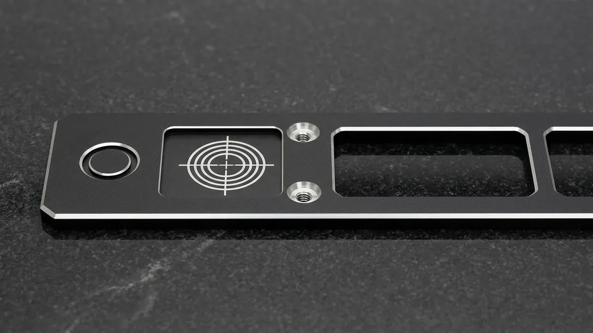
Adding text, alphanumeric serials, and graphical symbols to engineered components is essential for asset traceability, brand identification, and regulatory compliance. Furthermore, legible functional markings provide operational instructions, directional flow indicators, and electrical grounding schematics on mechanical hardware. However, selecting an improper marking technique can increase CNC machining cycle times by over 300% or compromise corrosion barriers. Therefore, mechanical design engineers must evaluate manufacturing economics, substrate metallurgy, and toolpath kinematics during initial CAD drafting.
Executive Summary & Engineering Takeaways (BLUF)
- CNC Metal Machining: Always specify recessed (engraved) text using single-line stick fonts or standard sans-serif typefaces (depth: 0.20 mm to 0.35 mm; min height: 2.5 mm). Raised (embossed) text requires volumetric pocket clearing of the entire surrounding face, multiplying machine cycle time and tooling costs.
- Injection Molding & Die Casting: Always specify raised (embossed) text on plastic or cast parts. Raised characters correspond to simple recessed cavities in the steel or aluminum mold tool, reducing tooling EDM hours and eliminating sink mark defects.
- Post-Anodizing Identification: Fiber laser marking (1064 nm) or MOPA laser surface ablation provides the highest contrast on black or color anodized aluminum (MIL-A-8625 Type II/III) while leaving the surrounding anodic film intact.
- CAD Documentation Best Practice: Do not model dense alphanumeric serial strings or 2D Data Matrix barcodes directly in 3D CAD solids. Define marking boundaries, font specifications, and depth tolerances in 2D manufacturing drawings (PDF/DXF) to prevent CAD polygon bloat.
Article Engineering Navigation
- 1. Part Marking Fundamentals: Recessed Engraved vs. Raised Embossed Text
- 2. CNC Mechanical Engraving: Cutters, Fonts, Feeds & Speeds
- 3. Laser Marking, Engraving, and Annealing Technologies
- 4. Text Design Guidelines for Injection Molded Parts
- 5. Surface Finishing Synergy: Silkscreen, Pad Printing & Chemical Etching
- 6. Comprehensive DFM Checklist & CAD Modeling Best Practices
- 7. Technical Engineering FAQ
1. Part Marking Fundamentals: Recessed Engraved vs. Raised Embossed Text
The primary geometric decision in part identification is choosing between recessed (engraved) text and raised (embossed) characters. While both configurations produce legible markings, their manufacturing physics diverge completely depending on whether the workpiece is subtractively machined or net-shape molded. A design choice that takes seconds in CAD can add substantial machining time on the shop floor.
In CNC milling, recessed engraved text is cut directly into the component surface using a rotating micro ball-nose cutter or conical V-bit. The cutting tool traverses the centerline or contour of each character in a single pass or minimal depth step-downs. Material removal is strictly confined to the stroke volume of the letters. Total toolpath displacement remains minimal, and the operation rarely adds more than a few minutes to overall spindle run time.
Conversely, producing raised embossed text on a CNC machined part requires removing all surrounding raw material across the entire component face down to the letter floor. Because the clearances between adjacent letters and enclosed loops (such as in letters “A”, “B”, “D”, “O”, “P”, “R”) are minuscule, machine operators cannot use standard 6 mm or 10 mm end mills. Instead, a micro end mill (often 0.5 mm to 1.5 mm diameter) must clear hundreds of cubic millimeters of raw metal at extremely low feed rates. Volumetric pocket clearing with micro-cutters drastically accelerates tool deflection, tool wear, and machine cycle time.
In stark contrast, injection molding and die casting invert this manufacturing logic. When an engineer specifies raised text on a plastic component, the corresponding tool cavity in the steel mold core (P20, NAK80, or H13) is a recessed feature. Machinists easily engrave recessed cavities into mold inserts using high-speed CNC milling or CNC sinker EDM (Electrical Discharge Machining) with graphite micro-electrodes. Once the mold tool is finished, millions of molded parts reproduce the raised text automatically during the injection cycle with zero cycle time penalty.
| Marking Technology | Material Compatibility | Tactile Relief & Profile | Production Cycle Time | Abrasion & Chemical Durability | Primary Industrial Use Cases |
|---|---|---|---|---|---|
| CNC Mechanical Engraving | Aluminum, stainless steel, brass, titanium, POM, PEEK, ABS | Recessed groove (0.15 mm to 0.40 mm depth) | Moderate (1 to 5 min per face) | Extremely High (Immune to surface wear and solvent wash) | Permanent serial plates, hydraulic valve port designations, calibration scales |
| Molded Raised Embossing | Thermoplastics (PC, ABS, PA66), die-cast zinc and aluminum | Raised relief (0.20 mm to 0.50 mm height) | Zero added cycle time during molding | High (Integral to base polymer substrate) | Enclosure branding logos, polymer recycling codes (SPI resin IDs), internal date clocks |
| Fiber Laser Surface Ablation | Anodized aluminum (Type II & III), blackened steel, painted metals | Near-flush (< 0.01 mm ablation) | Very Fast (2 to 15 seconds per part) | High (Permanent optical contrast on anodic layer) | High-density 2D Data Matrix codes, aerospace serialization, avionics front panels |
| Laser Annealing / Darkening | Stainless steels (304, 316L, 17-4PH), titanium alloys (Ti-6Al-4V) | Essentially flush (negligible surface relief) | Fast (5 to 30 seconds) | Maximum (Sub-surface oxidation; preserves passivated layer) | Medical surgical tools, food processing machinery, sterile cleanroom instruments |
| Silkscreen & Pad Printing | Painted metals, bare plastics, powder-coated enclosures, glass | Topical ink deposit (0.01 mm to 0.03 mm thickness) | High Batch Speed (Requires fixture and cure time) | Moderate (Requires epoxy ink to resist alcohol/MEK rubs) | Multi-color brand graphics, illuminated instrument dials, consumer electronics icons |
| Electrochemical Etching | Conductive metals (stainless steel, tool steel, carbide) | Controlled chemical recess (0.005 mm to 0.025 mm) | Moderate (Manual stencil placement and rinse) | High (Zero mechanical stress or heat-affected zone) | Thin-gage steel shims, razor blades, precision vernier scale rules |
2. CNC Mechanical Engraving: Cutters, Fonts, Feeds & Speeds
Mechanical engraving on high-speed CNC machining centers provides a rugged, tactile marking that survives abrasive operating environments, heavy steam cleaning, and post-machining chemical processing. Unlike shallow surface laser etching that merely alters optical emissivity, rotary mechanical engraving cuts deep U-groove channels with defined depth-to-width ratios, controlled root radii, and clean top edge deburring chamfers to ensure permanent tactile legibility under extreme industrial wear.
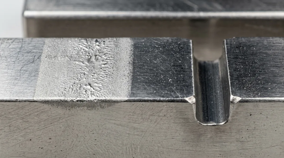
In mechanical engraving, cutter geometry governs stroke definition and edge finish. Machinists select between two primary tool categories:
- Conical V-Point Engraving Cutters (Half-Round or D-Bit): Featuring included tip angles of 30°, 45°, 60°, or 90° with a microscopic flat tip radius (typically 0.05 mm to 0.20 mm). The conical cross-section provides immense structural shank stiffness compared to cylindrical micro-tools. Furthermore, the depth of cut directly controls the resulting stroke width: deeper cuts produce wider lines. They are ideal for single-line stick fonts in metals.
- Micro Solid Carbide Ball-Nose End Mills: Utilizing micro-diameters ranging from 0.40 mm to 1.50 mm with 2 or 3 flutes. Ball-nose cutters produce rounded channel bottoms that eliminate micro-notch stress concentrations, making them mandatory for dynamic aerospace components subjected to fatigue loads.
- Diamond Drag Engravers (Non-Rotating): A spring-loaded, industrial monocrystalline or PCD diamond stylus is dragged across the metal surface without spindle rotation. Diamond dragging produces crisp, microscopic scribed lines on pre-polished or gold-plated surfaces without generating chips or burrs.
Font typography is a critical DFM parameter. Mechanical CAD models should strictly utilize sans-serif typefaces (such as Arial, Helvetica, Calibri, or DIN 1451) or specialized single-line stick fonts (such as ISO 3098 or CAM centerline fonts). Designers must avoid serif typefaces (such as Times New Roman or Georgia). Serif fonts feature sharp decorative baseline tails, variable stroke widths, and intricate interior corners. Cutting these minute serif features requires microscopic tools (< 0.3 mm) and extensive cycle times, while creating fragile edge corners where micro-burrs inevitably accumulate.
| Workpiece Material Substrate | Minimum Font Height (H) | Minimum Line Stroke Width (W) | Recommended Engraving Depth (D) | Optimal Tool Geometry | Typical Spindle Speed & Feed Rate |
|---|---|---|---|---|---|
| Aluminum Alloys (6061-T6, 7075-T651) | 2.5 mm (0.100 in) | 0.35 mm (0.014 in) | 0.20 mm to 0.30 mm | 60° V-bit (0.1 mm tip) or 0.5 mm ball end mill | 24,000 to 40,000 RPM | 600 to 1,200 mm/min |
| Stainless Steels (304, 316L, 17-4PH) | 3.0 mm (0.120 in) | 0.40 mm (0.016 in) | 0.15 mm to 0.25 mm | 90° AlTiN-coated micro V-bit or 0.4 mm ball mill | 15,000 to 24,000 RPM | 200 to 450 mm/min |
| Titanium Alloys (Ti-6Al-4V Grade 5) | 3.5 mm (0.140 in) | 0.45 mm (0.018 in) | 0.15 mm to 0.20 mm | 60° micro solid carbide (nano-composite TiAlSiN) | 12,000 to 18,000 RPM | 150 to 300 mm/min |
| Brass & Copper Alloys (C3604, C11000) | 2.0 mm (0.080 in) | 0.30 mm (0.012 in) | 0.25 mm to 0.40 mm | 45° polished single-flute carbide engraver | 24,000 to 35,000 RPM | 800 to 1,500 mm/min |
| Engineering Plastics (POM-C, PEEK, Nylon) | 2.5 mm (0.100 in) | 0.35 mm (0.014 in) | 0.25 mm to 0.35 mm | Single-flute razor-sharp uncoated carbide bit | 18,000 to 28,000 RPM | 1,000 to 2,000 mm/min |
Controlling surface burrs is a critical challenge in mechanical CNC engraving. When a cutting tool exits a letter stroke, ductile metals (such as 6061-T6 aluminum and 304 stainless steel) deform plastically, throwing micro-burrs along the top rim. In our precision facility, we employ three manufacturing counter-measures:
- Face Pre-Milling Sequence: Perform the face fly-cutting or shell-milling operation first, execute the engraving routine with climb milling (down-milling) to direct cutting forces downward into the workpiece, and follow with a secondary ultra-light facing pass (0.02 mm depth of cut) to shear off microscopic burrs flush with the surface plane.
- Spring-Loaded Floating Tool Holders: For large sheet metal enclosures or cast housings exhibiting slight surface waviness (tolerance runout up to ±0.4 mm), a spring-loaded floating engraving spindle maintains consistent mechanical contact pressure, ensuring uniform engraving depth across the entire face without gouging.
- Abrasive Media Blasting: Subjecting engraved components to fine glass bead blasting (#100 to #150 grit) or micro-vapor honing removes feather burrs while providing a uniform matte background that enhances engraving legibility.
3. Laser Marking, Engraving, and Annealing Technologies
Industrial laser marking has become the benchmark method for non-contact, permanent identification across precision CNC machined and fabricated parts. In our precision facility, pulsed fiber lasers vaporize thin black anodized coatings on aluminum enclosures, exposing the pristine bare metallic substrate underneath to create high-contrast, machine-readable 2D Data Matrix codes and crisp alphanumeric serial strings with zero heat-affected dimensional distortion.
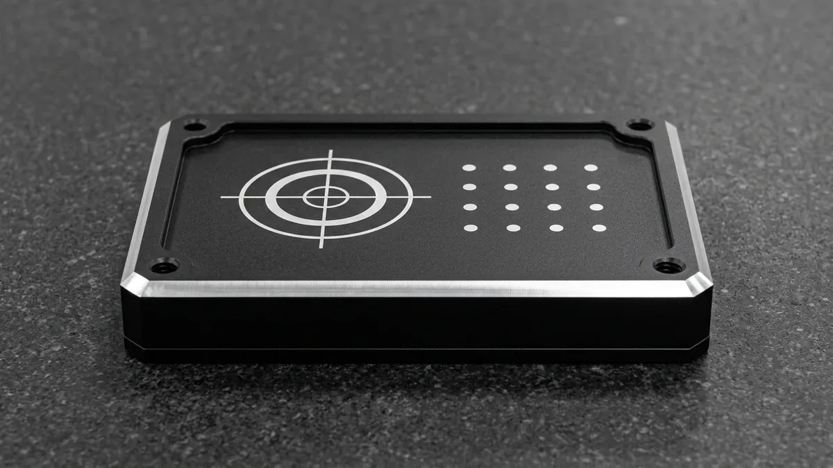
Selecting the correct laser technology depends on the workpiece material substrate and the required interaction physics. The four primary industrial laser marking categories include:
- Fiber Laser Systems (1064 nm Wavelength): The undisputed workhorse for metal fabrication. Diode-pumped ytterbium fiber lasers produce a concentrated near-infrared beam that couples efficiently into metals (aluminum, steels, titanium, brass, nickel alloys). They are widely used for surface ablation, deep trench engraving, and high-speed serialization.
- MOPA Fiber Lasers (Master Oscillator Power Amplifier): Advanced fiber laser platforms allowing independent control of pulse duration (from 2 ns to 500 ns) and pulse frequency (up to 4 MHz). Short pulse widths (2 to 10 ns) minimize thermal conduction, enabling crisp white or deep black marking on anodized aluminum without micro-cracking the surrounding anodic oxide layer. On titanium and stainless steels, MOPA lasers control oxide layer thicknesses to produce vivid rainbow or dark black annealing colors without material vaporization.
- UV “Cold” Lasers (355 nm Wavelength): Ultraviolet lasers operate via photochemical ablation (breaking molecular bonds directly rather than relying on thermal vaporization). With a microscopic spot size (< 15 μm) and virtually zero Heat-Affected Zone (HAZ), UV lasers are mandatory for sensitive medical polymers (PEEK, PTFE, silicone, polycarbonates) and flame-retardant electrical plastics without yellowing or charring.
- CO2 Lasers (10,600 nm / 10.6 μm Wavelength): Operating in the far-infrared spectrum, CO2 lasers are absorbed effectively by non-metallic organic substrates. They excel at engraving clear acrylics (PMMA), wood, elastomers, and glass instrument faceplates.
One of the most widespread engineering applications is post-anodizing fiber laser marking on CNC machined aluminum components. When an aluminum housing receives MIL-A-8625 Type II or Type III anodizing, organic or inorganic dye molecules saturate the porous aluminum oxide layer. When targeted by a focused fiber laser beam, the intense optical energy selectively vaporizes the organic dye in the top 10 μm to 20 μm, unmasking the natural bright white aluminum oxide underneath. Because the surrounding anodic film remains intact and only the dye layer is ablated, the marked text achieves crisp visual contrast while preserving the corrosion resistance of the surrounding anodic film (validate marked areas by ASTM B117 salt spray).
| Laser Source Type | Optical Wavelength | Physical Interaction Mode | Pulse Width Range | Spot Size (Ø) | Target Substrate Materials |
|---|---|---|---|---|---|
| Standard Q-Switched Fiber | 1064 nm (NIR) | Thermal Ablation & Micro-Melting | 80 to 120 ns (Fixed) | 30 to 50 μm | Carbon steels, tool steels, raw cast aluminum, brass |
| MOPA Fiber Laser | 1064 nm (NIR) | Controlled Surface Annealing & Dye Bleaching | 2 to 500 ns (Variable) | 20 to 40 μm | Anodized aluminum (Type II/III), stainless 316L, titanium Ti-6Al-4V |
| UV Diode-Pumped Solid-State | 355 nm (UV) | Photochemical Cold Ablation (Zero HAZ) | 10 to 25 ns | 10 to 20 μm | White polycarbonates, PEEK, PTFE, silicone, circuit board laminates |
| RF-Excited Sealed CO2 | 10,600 nm (Far-IR) | Thermal Vaporization & Pyrolysis | Continuous / Microsecond | 80 to 150 μm | Acrylic (PMMA), wood, elastomers, optical glass |
For machine-readable symbols such as MIL-STD-130 UID Data Matrix codes or ISO/IEC 18004 QR codes, optical contrast and cell geometry determine verification compliance. Automatic optical verification systems evaluate cell size, print growth, axial non-uniformity, and reflectance margin. To ensure an “A-Grade” verification score, design engineers must allocate a mandatory Quiet Zone (a blank perimeter border clear of any text, knurling, or surface texture) equal to at least one Data Matrix cell width on every side (ISO/IEC 16022 minimum; 2 to 4 cells recommended for robust verification).
4. Text Design Guidelines for Injection Molded Parts
When transitioning from prototype machining to injection molding or high-pressure die casting, part marking geometry must align with polymer rheology and tool ejection kinematics. In plastic molding, text is almost universally specified as raised embossed lettering on the cosmetic surface of the part, standing 0.20 mm to 0.40 mm above the base wall.
Molding engineers must adhere to four essential DFM rules when incorporating molded text and symbols:
- Mandatory Draft Angles on Letter Sidewalls: Every stroke of an embossed letter requires a draft angle of at least 1.0° to 1.5° per side (increased to 2.0° to 3.0° if the mold cavity features mold-tech EDM spark erosion texture). Vertical, zero-draft letter walls scrape against the mold steel during mold opening, creating white witness stress marks, scuffing, and retained plastic burrs.
- Height Capped Relative to Nominal Wall Thickness: Embossed letter height should never exceed 20% to 30% of the nominal component wall thickness (maximum height: 0.50 mm). Excessively tall raised characters create localized thermal mass concentrations in the mold, drawing plastic away during cooling and inducing severe sink mark depressions on the cosmetic Class-A outer face.
- Draw Direction Orientation: Position text perpendicular (normal) to the mold parting direction. If text is placed on vertical outer walls parallel to mold draw, the tool requires expensive side-action slide cams or lifters with mechanical interlocks, substantially increasing mold tool fabrication costs.
- Interchangeable Date Stamp Plugs & Cavity Markers: For high-volume production molds, critical traceability information (such as production month, year clock, cavity number, and material resin symbol) should be integrated via standard interchangeable DME or Hasco date indicator inserts. This allows tool operators to rotate the date dial monthly without machining new mold cores.
5. Surface Finishing Synergy: Silkscreen, Pad Printing & Chemical Etching
Many engineered assemblies require high-visibility multi-color brand logos, illuminated instrumentation graphics, or markings on highly contoured geometries where laser scan heads or mechanical cutters cannot operate line-of-sight. In these scenarios, post-machining printing and chemical marking technologies deliver specialized manufacturing solutions.
Silkscreen Printing (Screen Printing): Highly cost-effective for flat sheet metal panels, extruded instrument faceplates, and powder-coated electronic rack chassis. A precision polyester or stainless steel wire mesh screen (typically 200 to 350 mesh count) transfers two-component epoxy or polyurethane ink through photo-emulsion stencils onto the part. When thermal-baked at 120°C to 150°C, epoxy inks cross-link into a solvent-resistant bond that withstands over 100 double-rubs of isopropyl alcohol (IPA) and methyl ethyl ketone (MEK) per ASTM D5402 standards.
Pad Printing (Tampography): Tailored for printing on compound 3D curved surfaces, ergonomic tool handles, and deeply recessed plastic cavities. An etched steel plate (cliché) holds ink in micro-etched recesses, which is picked up by a deformable silicone rubber pad and transferred conformally onto the contoured workpiece. The soft silicone pad wraps around complex curvatures without ink distortion.
Engraved Paint Fill (Color Infill): A premium aesthetic technique widely specified on high-end camera housings, luxury automotive knobs, and scientific dials. The component is first CNC milled with recessed text (0.3 mm to 0.5 mm depth). Enamel or acrylic ink is flooded into the recessed grooves and cured. The excess surface paint is subsequently wiped or diamond-lapped clean, leaving perfectly crisp, flush color lettering protected from physical abrasion within the recessed pockets.
Manufacturing Process Sequence Coordination: Achieving pristine part markings requires careful scheduling of surface preparation steps. The table below outlines the standard production sequence across common industrial finishes:
- Anodized Aluminum Housings: CNC Machining → Mechanical Deburring → Bead Blasting (#120 Glass Bead) → MIL-A-8625 Type II Anodizing & Sealing → Fiber Laser Marking (Ablates top color dye layer with high contrast).
- Passivated Stainless Medical Tools: CNC Machining → Ultrasonic Degreasing → ASTM A967 Chemical Passivation → MOPA Laser Annealing (Produces permanent dark mark without breaking passive chromium-oxide layer).
- Painted Sheet Metal Enclosures: Laser Cutting → CNC Press Brake Bending → PEM Standoff Insertion → Electrostatic Powder Coating (60 to 80 μm) → Silkscreen Printing → Infrared Convection Oven Bake (140°C for 30 min).
6. Comprehensive DFM Checklist & CAD Modeling Best Practices
Incomplete or ambiguous part marking annotations in CAD packages represent one of the leading causes of CAM programming delays and manufacturing quote revisions. By following structured CAD modeling protocols, design engineers streamline manufacturing throughput and ensure first-article inspection compliance.
| Inspection Parameter | Governing Standard | Measurement Instrument / Method | Acceptance Criteria |
|---|---|---|---|
| 2D Barcode Data Integrity | ISO/IEC 15415 / ISO/IEC 16022 (Data Matrix) | Calibrated Barcode Verifier (660 nm / White LED) | Grade A or B (Overall Symbol Grade ≥ 3.0 / 4.0) |
| Ink Coating Adhesion | ASTM D3359 (Cross-Hatch Tape Test) | Multi-blade cutter (1 mm lattice) + Pressure-sensitive tape | Class 4B or 5B (Zero flaking or lattice detachment) |
| Solvent & Rub Resistance | ASTM D5402 / MIL-STD-130 | IPA / MEK saturated cotton swab (1 kg downward force) | No visible ink erosion or legibility loss after 100 double rubs |
| Mechanical Engraving Depth | ISO 2768-mK / Engineering Drawing Callout | Optical Profile Projector or 2.5D Optical Vision System | Target depth ± 0.05 mm; uniform trough width |
| Corrosion Integrity Post-Laser | ASTM B117 (Neutral Salt Spray Exposure) | Environmental salt fog chamber (5% NaCl solution at 35°C) | No visible pitting or blooming after 96 to 240 hours |
To eliminate ambiguity before releasing CAD models to the manufacturing floor, engineers should verify their designs against the following Part Marking Engineering Checklist:
- 3D CAD Solid Modeling Protocol: Do not model dense alphanumeric serial strings, long patent notices, or complex 2D Data Matrix barcodes as extruded or cut 3D solid geometry in STEP or native CAD models. High-density polygon meshes drastically inflate CAD file sizes, trigger rendering lag, and cause CAM toolpath calculation crashes. Instead, model a simple reference boundary rectangle or plane, and detail the exact font, size, and content in the 2D technical drawing.
- 2D Drawing Callout Specificity: Explicitly state the marking process (e.g., “Laser mark character height 3.0 mm per MIL-STD-130 using Arial bold font; contrast color: bright white” or “CNC engrave depth 0.25 ± 0.05 mm; single-line font”). Avoid vague annotations such as “Mark part number here”.
- Edge Clearances & Assembly Baselines: Maintain a minimum clearance of at least 3.0 mm (0.120 in) between any engraved character and adjacent part edges, internal chamfers, O-ring sealing grooves, or fastener clearance holes. Markings placed too close to sealing lands can compromise pressure gaskets.
- Line Width to Cutter Ratio: Verify that the narrowest stroke width of every character is at least 1.2 times larger than the smallest planned engraving tool diameter. If the character loop is narrower than the tool, the CAM software will fail to generate an internal toolpath, resulting in missing character features.
- Post-Finishing Thickness Compensation: When parts receive thick coating finishes—such as electrostatic powder coating (60 to 100 μm) or heavy electroless nickel plating (25 to 50 μm)—shallow mechanical engravings will be completely buried and smoothed over. Either increase mechanical engraving depth to at least 0.50 mm or perform laser marking after final coating.
At AS Prototypes, we integrate part marking, micro-engraving, and laser serialization directly into our in-house precision CNC machining and injection molding manufacturing lines. Our facility provides comprehensive in-house metal surface finishes—including Type II and Type III hard anodizing, bead blasting, chemical passivation, and fiber laser marking—delivering fully verified, production-ready components backed by rigorous DFM reviews.
7. Technical Engineering FAQ
You should always select recessed engraved text for CNC machined components. Recessed engraving is cut directly along the character centerline using single-line or contour toolpaths, adding only a few minutes to total spindle cycle time. In contrast, embossed (raised) text requires volumetric pocket clearing of the entire surrounding face with fragile micro end mills, increasing machining cycle time by 300% or more and driving up production costs.
Designers should always specify simple sans-serif fonts such as Arial, Helvetica, Calibri, or DIN 1451, or single-line stick fonts (ISO 3098). Sans-serif fonts maintain uniform stroke widths and eliminate intricate baseline serifs. Serif typefaces (such as Times New Roman) require microscopic cutters (< 0.3 mm) to resolve sharp ornamental tails, which leads to tool chatter, frequent cutter breakage, and micro-burr accumulation.
When executed properly, fiber laser marking on anodized aluminum does not compromise corrosion resistance. The laser beam operates via selective photothermal ablation, vaporizing only the thin organic or inorganic dye molecules trapped in the upper 10 to 20 micrometers of the porous anodic oxide layer. Because the surrounding anodic film remains intact and marking depth is controlled, corrosion resistance against ASTM B117 salt spray exposure is retained when validated on marked samples while displaying sharp, permanent white contrast.
For CNC mechanical engraving in aluminum and steel, the recommended minimum font height is 2.5 mm to 3.0 mm with a stroke width of at least 0.35 mm and a depth of 0.20 mm to 0.30 mm. For injection molded parts, raised embossed text should have a minimum height of 2.0 mm with at least 1.0 degree of draft angle per side. For fiber laser marking, character heights down to 0.8 mm and line widths of 0.05 mm can be legibly resolved.
Designers should avoid modeling dense alphanumeric serial numbers, 2D Data Matrix codes, or detailed logos as 3D solid geometry in STEP or IGES files, as this causes severe polygon bloat and CAM file crashes. The industry best practice is to place a cosmetic bounding box on the 3D solid and specify all text strings, font styles, depth tolerances (ISO 2768-mK), and marking techniques (laser, engraving, or silkscreen) in the accompanying 2D technical drawing (PDF/DXF).
Partner with Our Precision CNC Machining & Engineering Team
Eliminate tool deflection, residual stress distortion, and tolerance stack-up risks before production begins. Upload your 3D CAD files (STEP/IGES) and 2D GD&T drawings for a comprehensive shop-floor DFM review and custom quotation.
Upload 3D CAD for Engineering DFM & RFQ