

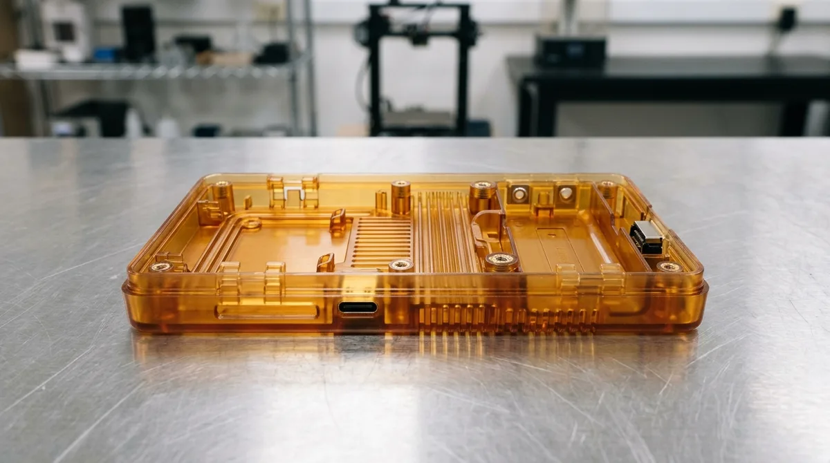
Engineering Summary (BLUF): Selecting the optimal rapid prototyping technology depends directly on target material properties, required dimensional fidelity, batch volume, and development stage. For low-stress form and ergonomic verification, SLA and SLS additive manufacturing provide complex organic contours within 4 to 8 business days. For high-stress structural validation requiring wrought mechanical integrity and critical bearing fits (±0.010 mm), high-speed 3/4-axis CNC milling remains the industry benchmark. Polyurethane vacuum casting bridges the gap for 10 to 50 cosmetic or functional polymer units without hard tooling capital, while precision sheet metal fabrication and rapid aluminum tooling (18 to 35 business days) support ruggedized chassis envelopes and pre-production injection runs.
Accelerating modern hardware development cycles demands rigorous physical validation before committing capital expenditure to production-grade tooling. Specifically, multidisciplinary engineering teams must verify mechanical clearances, assembly kinematics, thermal dissipation, and ergonomic tactile feel across successive iteration loops.
Relying solely on digital Finite Element Analysis (FEA) and CAD simulations introduces significant commercial risk. Real-world operating environments frequently reveal micro-deflections, thermal expansion mismatches, and unexpected stress concentrations that pure software models fail to capture.
At AS Prototypes, our comprehensive in-house manufacturing facility combines high-precision subtractive CNC machining services, industrial additive polymer and metal sintering, silicone polyurethane vacuum casting, and precision custom sheet metal fabrication. Below is an exhaustive engineering guide comparing core rapid prototyping technologies, material envelopes, design rules, and cost-reduction pathways.
Engineering Taxonomy: Core Rapid Prototyping Technologies Compared
Prototyping processes divide into three primary manufacturing paradigms: additive layer generation, subtractive billet machining, and formative replication. Each method imposes distinct geometric constraints, isotropic strengths, and surface roughness profiles.
Understanding these trade-offs enables mechanical designers and hardware procurement teams to sequence prototypes logically through Proof of Concept (POC), Engineering Verification Testing (EVT), and Design Verification Testing (DVT) stages.
| Technology | Baseline Tolerances | Optimal Batch Volume | Factory Turnaround | Tooling Investment | Core Mechanical Applications |
|---|---|---|---|---|---|
| High-Speed CNC Milling / Turning | ISO 2768-mK (±0.010 mm critical fits) | 1 – 200 pcs | 4 – 8 Business Days | Near Zero (Direct CAM Setup) | High-load structural brackets, gearbox housings, bearing bores, and heatsinks. |
| Stereolithography (SLA / DLP) | ±0.10 mm to ±0.15 mm | 1 – 15 pcs | 4 – 8 Business Days | Zero Tooling | Cosmetic presentation models, optical light pipes, and master patterns for casting. |
| Selective Laser Sintering (SLS / MJF) | ±0.15 mm to ±0.25 mm | 1 – 100 pcs | 4 – 8 Business Days | Zero Tooling | Durable snap-fit enclosures, ducting, functional test fixtures, and living hinges. |
| Direct Metal Laser Melting (SLM / DMLS) | ±0.10 mm to ±0.20 mm | 1 – 10 pcs | 7 – 12 Business Days | Zero Tooling | Topology-optimized aerospace brackets, conformal cooling channels, and medical implants. |
| Polyurethane Vacuum Casting | ±0.15 mm per 100 mm | 10 – 50 pcs | 7 – 12 Business Days | Low (Soft Silicone Tooling) | Pre-production polymer bezels, overmolded gaskets, and clinical trial hardware. |
| Precision Sheet Metal Fabrication | ±0.15 mm to ±0.25 mm (±0.5° bend) | 5 – 500 pcs | 4 – 8 Business Days | Near Zero (Universal CNC Press Tooling) | Electronic enclosures, rackmount subracks, RF shielding cans, and busbars. |
| Rapid Tooling & Bridge Molding | ±0.05 mm to ±0.10 mm | 100 – 5,000+ pcs | 18 – 35 Business Days | Moderate (Aluminum MUD / P20 Inserts) | Pilot production runs using true production-grade engineering thermoplastics. |
Additive Manufacturing: High-Resolution SLA, SLS, and Metal SLM
Additive manufacturing serves as the foundational rapid prototyping technology for early-stage geometry evaluation. By slicing 3D CAD data into discrete horizontal layers, additive processes construct intricate topologies without the cutter access limitations inherent to rotational machining.
However, industrial additive systems exhibit pronounced distinctions across photopolymerization, powder bed fusion, and laser sintering mechanisms. Matching the technology to mechanical loading requirements is critical.
Stereolithography (SLA) and Digital Light Processing (DLP)
SLA utilizes an ultraviolet laser beam (typically 355 nm or 405 nm) focused through galvanometer mirrors to trace cross-sectional vectors across a vat of photosensitive liquid resin. Liquid monomers cross-link into solid polymers upon photon exposure.
Because SLA creates virtually smooth surface finishes with minimal layer stair-stepping (0.025 mm to 0.050 mm layer heights), it excels at visual presentation models, optical lenses, and microfluidic test fixtures. Nevertheless, photopolymers remain sensitive to prolonged ultraviolet exposure and environmental humidity, necessitating secondary protective UV-blocking clear coats for field testing.
Selective Laser Sintering (SLS) of Engineering Polyamides
Unlike liquid vat printing, SLS employs a high-power CO₂ laser (10.6 μm wavelength) to fuse micronized thermoplastic powder particles (such as Nylon PA12 and PA11) layer by layer within a heated build envelope. The surrounding unsintered powder cake provides continuous mechanical support, completely eliminating the need for sacrificial support geometry.
This self-supporting nature allows engineers to build complex internal ducting, fluid manifolds, and nested kinematic assemblies directly. SLS PA12 components exhibit near-isotropic tensile strength (up to 48 MPa) and excellent chemical resistance, making them suitable for functional automotive intake ducts, consumer drone chassis, and ruggedized snap-fit closures.
Selective Laser Melting (SLM / DMLS) for Dense Metal Hardware
When functional verification demands genuine metallic alloys capable of withstanding extreme thermal gradients or elevated shear loads, Direct Metal Laser Melting (SLM / DMLS) fuses gas-atomized metal powders under an inert argon atmosphere. Typical engineering alloys include Ti-6Al-4V Grade 5, 316L stainless steel, AlSi10Mg aluminum, and Inconel 718.
SLM parts achieve densities exceeding 99.7%, approaching wrought tensile strengths after vacuum stress-relief annealing (and hot isostatic pressing where fatigue-critical). Consequently, aerospace and medical device teams rely on SLM prototypes to test weight-minimized organic brackets and conformal cooling inserts before committing to high-tonnage forging or casting dies.
Subtractive Prototyping: 3/4-Axis CNC Milling & Swiss Turning
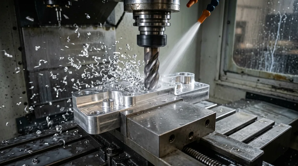
While additive technologies dominate organic form verification, subtractive CNC machining remains the undisputed gold standard for structural functional prototypes. Direct machining from wrought extruded billet guarantees 100% mechanical density and known fatigue properties without layer boundary weaknesses.
In our precision prototype machine shop, high-speed 3-axis and 4-axis vertical machining centers (VMCs) handle 75% to 85%+ of daily component production. Dedicated 5-axis simultaneous machining centers serve as specialized assets for closed impellers, complex aerospace airfoils, and multi-sided hydraulic valve blocks.
DFM Rules for CNC Machined Prototypes
To maximize machining efficiency and control prototype costs, engineers should observe several fundamental Design for Manufacturability (DFM) rules during CAD modeling:
- Internal Corner Radii: Sharp 90-degree internal pocket corners are geometrically impossible with rotary cutters. Designers should specify internal radii R ≥ 0.33 × pocket depth (and always larger than the cutter radius) to allow continuous toolpath motion without tool deflection.
- Pocket Depth Ratios: Keep pocket depths under 4× cutter diameter. Deeper cavities require long-reach toolholders, inducing chatter and deteriorating surface roughness (Ra).
- Standardized Fastener Counterbores: Standardize tapped hole sizes (e.g., M3, M4, M5) across the BOM to minimize spindle tool changes during the CNC program.
- Tolerancing Restraint: Apply general tolerances per ISO 2768-mK. Reserve critical drawing tolerances of ±0.010 mm to ±0.020 mm strictly for functional bearing press fits, dowel pin locations, and dynamic seal surfaces.
Swiss-Type Lathe Turning for Miniature Shafts
For cylindrical and coaxial prototypes with outer diameters under 32 mm and length-to-diameter (L/D) ratios exceeding 4:1, Swiss-type CNC lathes offer superior cycle speeds and concentricity. The sliding headstock feeds bar stock through a carbide guide bushing directly adjacent to the cutting tools, preventing workpiece deflection under radial cutting pressure.
Polyurethane Vacuum Casting: The Bridge Tooling Standard
When hardware development advances into clinical trials, field testing, or marketing photo samples requiring 10 to 50 plastic housings, neither single-piece 3D printing nor production steel tooling is commercially sensible. 3D printing becomes cost-prohibitive at scale, while steel injection molds require extensive tooling lead times.
Polyurethane vacuum casting represents the optimal bridge manufacturing process. It produces end-use polyurethane components matching the mechanical toughness, flame retardance, and surface texture of injection-molded thermoplastics at a fraction of upfront investment.
The Vacuum Casting Technical Sequence
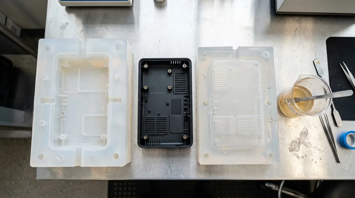
The vacuum casting workflow follows four precise process stages:
- Master Pattern Fabrication: A master pattern is machined from aluminum or printed via high-resolution SLA resin. Technicians hand-finish the master to the required cosmetic texture, applying SPI A-2 polish, VDI mold textures, or custom paint.
- Silicone Encapsulation: The pattern is suspended within a casting frame with gating sprues and riser vents attached. Degassed liquid platinum-cure silicone rubber is poured over the master and thermally cured in an oven at 40°C to 50°C.
- Parting Line Separation: Skilled toolmakers cut the cured silicone block along the parting line with a scalpel, extracting the master pattern to reveal a pristine negative mold cavity.
- Vacuum Injection: Two-component polyurethane resin is degassed under high vacuum (< 1 mbar) to extract trapped micro-bubbles, mixed automatically, and poured into the silicone tool. The tool cures at 65°C before part demolding.
Because silicone molds gradually absorb plasticizers and lose dimensional tension over repeated thermal cycles, a single silicone tool yields 15 to 25 premium parts before requiring replacement. Formulations accurately emulate ABS (e.g., Hei-Cast 8150), Polycarbonate, Polypropylene, and Shore 30A to 90A elastomers.
Precision Sheet Metal Prototyping: Laser Cutting & Air Bending
Hardware products housing high-power electronic power supplies, industrial rack servers, or automotive control modules require rigid, electrically conductive, and EMI-shielded enclosures. Precision sheet metal fabrication delivers functional structural shells within 4 to 8 business days.
Unlike casting or molding, sheet metal processing requires no dedicated tooling molds. Parts transition directly from 2D flat unfolded CAD patterns to CNC cutting and forming equipment.
Laser Profiling and Press Brake Mechanics
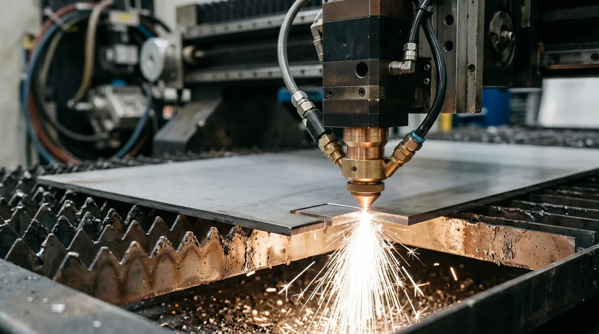
High-power fiber lasers (3 kW to 12 kW) use nitrogen assist gas (or oxygen for thicker mild steel) to cut cold-rolled steel, 5052-H32 aluminum, and 304 stainless steel with narrow kerf widths (roughly 0.1 to 0.3 mm) and clean, dross-free edges. Corner relief notches are cut at intersecting bend lines to prevent metal tearing during forming.
Subsequent bending occurs on CNC hydraulic press brakes using universal hardened V-dies and punches. Air bending compensates for material springback by over-bending slightly past the intended angle. Engineers calculate flat blank unfolding using standardized K-factor equations:
Bend Allowance (BA) = (π / 180) × θ × (R + K × t)
Where θ represents bend angle in degrees, R is inside bend radius, t is sheet thickness, and K denotes the neutral axis shift factor (0.33 ≤ K ≤ 0.50 depending on alloy ductility). Maintaining minimum bend radii R ≥ t prevents outer-fiber tensile cracking.
Rapid Tooling & Bridge Injection Molding for Low-Volume Runs
When physical verification transitions from DVT to pre-production validation (PVT), engineering teams need hundreds or thousands of parts molded in production-intent resins (such as glass-filled PA66, polycarbonate-PBT blends, or flame-rated UL94-V0 ABS).
Rapid aluminum tooling bridges this gap before committing heavy capital expenditure to multi-cavity hardened steel production molds. By utilizing standardized Master Unit Die (MUD) frames and CNC milling high-strength 7075-T651 aluminum or P20 pre-hardened steel cavity inserts for rapid injection molding, prototype shops deliver molded parts within 18 to 35 business days.
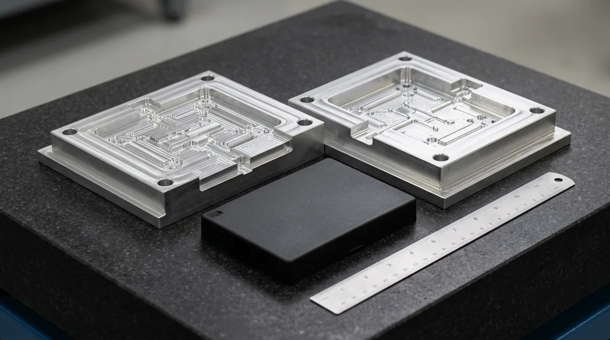
Tooling Life and Engineering Feasibility
Aluminum 7075 exhibits thermal conductivity roughly four times higher than P20 tool steel, resulting in significantly shorter mold cooling cycle times and reduced part warping. An aluminum rapid mold easily supports 1,000 to 10,000 injection cycles when processing non-abrasive resins.
Design teams validate gate placement, parting line shutoffs, weld lines, and mold shrinkage characteristics under actual factory molding pressures, identifying potential sink marks or gas traps well before launching mass-production tooling.
Surface Finishing and Environmental Post-Processing Protocols
Rapid prototypes frequently require secondary surface finishing to satisfy aesthetic presentation criteria, corrosion resistance, or electrical insulation requirements. Integrating the correct post-processing specification into drawing packages ensures predictable assembly fit.
Crucially, chemical and electrochemical surface treatments alter part dimensions. For example, Type II sulfuric anodizing forms a coating roughly 10 to 15 microns thick (about 5 to 8 microns of growth per surface), while Type III hardcoat anodizing forms a coating roughly 40 to 50 microns thick (about 50% penetration and 50% surface growth, or 20 to 25 microns per surface). Engineers must adjust CAD thread dimensions and precision bores prior to machining to accommodate coating thickness changes.
| Finishing Process | Applicable Materials | Dimensional Change per Surface | Industry Specification | Primary Functional Benefit |
|---|---|---|---|---|
| Bead Blasting (#80 – #150) | Aluminum, Stainless, Titanium | Negligible (< 2 µm erosion) | ASME B46.1 | Removes cutter tool marks, yielding a uniform satin non-directional matte finish. |
| Sulfuric Anodizing (Type II) | Aluminum 6061, 7075, 5052 | +5 µm to +8 µm growth | MIL-A-8625 Type II Class 1/2 | Atmospheric corrosion resistance, decorative organic dyeing (black, blue, red). |
| Hardcoat Anodizing (Type III) | Aluminum 6061, 7075 | +20 µm to +25 µm growth | MIL-A-8625 Type III Class 1/2 | Extreme abrasive wear resistance (roughly 400 to 600 HV surface layer) and dielectric insulation. |
| Chemical Film (Alodine / SurTec) | Aluminum Alloys | Zero measurable change (< 1 µm) | MIL-DTL-5541 Type II Class 3 | Preserves electrical surface conductivity for RF grounding while inhibiting oxidation. |
| Stainless Passivation | Stainless 303, 304, 316L, 17-4PH | Zero dimensional change | ASTM A967 / AMS 2700 | Chemical leaching of free exogenous iron to form a chromium-oxide passive barrier. |
| Vapor Smoothing (Chemical Smoothing) | SLS PA12, MJF Nylon, ABS | Negligible (liquefies surface crests) | ISO 4287 | Seals microscopic surface porosity on 3D printed nylon, providing fluid-tight sealed surfaces. |
Quality Verification & Metrology Standards for Rapid Prototypes
A prototype is only as valuable as the metrology data verifying its conformance to engineering specifications. Without rigorous dimensional inspection, design teams risk diagnosing false mechanical interferences caused by out-of-tolerance prototypes rather than true CAD defects.
Our in-house inspection laboratory operates climate-controlled metrology suites maintaining 20°C ± 0.5°C ambient standards to prevent thermal drift during high-precision measurements.
Coordinate Measuring Machine (CMM) Probing
For tight-tolerance geometric features, motorized Zeiss CMM touch-trigger probes verify true position, cylindrical bore concentricity, and planar parallelism directly against 3D CAD step files. Ruby sphere styli touch critical datums without surface marring, capturing volumetric data with measurement uncertainty on the order of a few micrometers.
Optical 3D Scanning and Laser Metrology
For organic contoured surfaces, vacuum-cast elastomer geometries, and thin-gauge stamped brackets where mechanical probe force could deflect flexible walls, non-contact blue-light 3D scanners capture dense point-cloud meshes. Color-coded deviation heatmaps compare physical scan models against nominal CAD geometry, instantly highlighting warp patterns or thermal shrinkage.
Frequently Asked Questions
Polyurethane vacuum casting using silicone tooling is the most cost-effective and accurate method for 15 to 30 plastic parts. A single silicone mold yields up to 25 units with injection-molded surface texture, dimensional accuracy of ±0.15 mm per 100 mm, and true production-grade polymer mechanical behavior without the high capital investment of steel tooling.
Both CNC machining and industrial additive manufacturing (SLA/SLS) deliver functional prototypes within 4 to 8 business days at AS Prototypes. CNC machining is ideal for structural metal alloys and tight bearing tolerances (±0.010 mm), whereas 3D printing accelerates low-stress organic shapes and lightweight internal lattice ducting.
Yes. Advanced dual-component polyurethane casting resins accurately simulate standard engineering thermoplastics. Formulations include ABS-like urethanes with high impact strength, PP-like flexible polymers, high-temperature formulations (HDT > 130°C), optical water-clear resins, and elastomeric rubbers ranging from Shore 30A to 90A.
We follow ISO 2768-mK as our standard baseline for all non-toleranced machined prototype dimensions. For critical mating interfaces, bearing journals, and dowel locating holes, our 3/4-axis CNC machining centers hold tight linear tolerances of ±0.010 mm to ±0.020 mm as specified on engineering drawings.
For Type II sulfuric anodizing, allow approximately +0.010 mm to +0.015 mm diameter growth (+0.005 mm to +0.008 mm per surface). For Type III hardcoat anodizing, anticipate +0.040 mm to +0.050 mm diameter buildup. Precision internal threads and dowel bores must be machined oversize or masked prior to electrochemical immersion to prevent out-of-tolerance assembly fits.
Accelerate Your Hardware Development Cycle
From single-piece concept 3D prints and precision CNC machined metal billets to low-volume polyurethane vacuum casting and rapid injection tooling, AS Prototypes delivers end-to-end prototyping capabilities under one roof. Upload your 3D CAD models today for expert DFM analysis and a comprehensive quotation within 24 hours.
Request DFM Review & Prototype Quotation →






