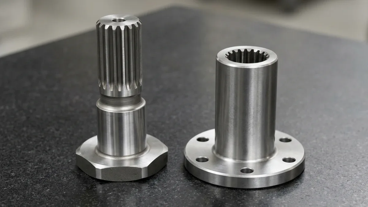
In high-torque industrial drivetrains, robotic actuators, and heavy automotive transmissions, splined shaft machining replaces vulnerable single-keyway joints with circumferentially distributed load-sharing teeth. While a standard parallel keyway concentrates torsional shear along one narrow slot, a precision spline distributes torque across 6 to 48+ engaging flanks, increasing torsional load capacity by 250% to 300% for an identical shaft diameter.
Achieving zero backlash, smooth axial sliding, and multi-million-cycle fatigue endurance requires tight control over tooth profile geometry, pitch-to-journal concentricity, and post-heat-treatment flank distortion. Depending on whether a design specifies DIN 5480 involute splines, DIN 5462 straight-sided keys, or DIN 5481 serrations, the machining route shifts between continuous gear hobbing, 4-axis CNC index milling, internal broaching, and power skiving.
Our Shenzhen gear-cutting facility machines custom splined shafts and internal hubs to ISO 2768-mK general tolerances, ±0.010–±0.020 mm (±0.0004″–±0.0008″) tooth thickness tolerances, and ≤ 0.010 mm (0.0004″) TIR journal concentricity. We deliver soft prototypes in 4–8 business days (Ex-Factory), hardened splines in 7–12 business days (Ex-Factory), and production batches in 7–30 business days (Ex-Factory).
Executive Summary & Engineering Takeaways (BLUF)
- Involute vs. Straight-Sided Fatigue Life: Involute splines (DIN 5480 / ISO 4156 / ANSI B92.1) with a 30° pressure angle and full fillet root reduce root stress concentration (Kt ≈ 1.4–1.7) by 40% to 50% vs. straight-sided splines (DIN 5462, Kt ≈ 2.5–3.2) while self-centering under torque.
- Crowned Splines for Misalignment: Longitudinal flank crowning (0.015–0.040 mm [0.0006″–0.0016″] modification) accommodates 0.5° to 1.5° dynamic angular misalignment without edge-loading or fretting wear.
- Agility vs. Volume Machining Selection: Multi-axis CNC turn-mill and 4-axis index milling deliver prototypes in 4 to 8 business days (Ex-Factory) without custom tooling, whereas CNC gear hobbing and internal broaching optimize unit cost for 50 to 5,000+ piece batches.
- Blind-Shoulder & Hardened Solutions: Power skiving cuts splines within 2.0 to 3.5 mm (0.079″ to 0.138″) of a blind shoulder, while Wire EDM and vitrified CBN profile grinding hold ±0.005 mm (±0.0002″) on 58 to 62 HRC steel.
- Over-Pins Metrology Verification: Effective tooth thickness is verified via tungsten carbide pins (M-dimension micrometer check within ±0.010 mm [±0.0004″]), GO/NO-GO spline gauges, and on-request Zeiss Contura Bridge CMM scanning.
Article Engineering Navigation
- 1. Spline Standards & Tooth Profile Architectures
- 2. Quantitative Torque & Shear Stress Derivation
- 3. Shop-Floor Splined Shaft Machining Processes
- 4. Metallurgy, Heat Treatment & Distortion Control
- 5. 4-Step Shop-Floor Manufacturing SOP
- 6. Over-Pins Metrology, Gauging & Defect Matrix
- 7. When NOT to Choose Splined Shafts & Trade-Offs
- 8. Technical Engineering FAQ
1. Spline Standards & Tooth Profile Architectures: Involute, Straight-Sided, Crowned & Serrated
Selecting the correct tooth geometry is the primary design decision in splined shaft machining, dictating load-centering kinematics, fatigue notch sensitivity, and cutter availability. International drivetrain design relies on four standardized profile families: involute splines, parallel-key straight-sided splines, longitudinally crowned involute splines, and fine-pitch triangular serrations.
DIN 5480-1, ISO 4156, and ANSI B92.1 involute splines generate curved flanks from a base circle across modules m = 0.5–10.0 mm (0.020″–0.394″) at 30°, 37.5°, or 45° pressure angles. Under torque, 30° inclined flanks self-center the mating hub on the pitch circle, while a full fillet root (rf ≈ 0.30m–0.45m) cuts root bending stress by 40%–50%.
Straight-sided splines (DIN ISO 14, DIN 5462, DIN 5463) use 6–16 parallel keys requiring ground minor or major diameters for coaxiality. Because 90° root corners raise notch sensitivity (Kt ≈ 2.5–3.2), they suit low-speed sliding PTO sleeves, whereas crowned involute splines (0.015–0.040 mm [0.0006″–0.0016″] crown) absorb 0.5°–1.5° misalignment and DIN 5481 45°/60° serrations protect hollow tubes.
| Spline Architecture | Standards | Pressure Angle | Centering Method | Fatigue Index | Recommended Application / When to Choose |
|---|---|---|---|---|---|
| Involute Spline (Fillet Root) | DIN 5480-1, ISO 4156, ANSI B92.1 | 30° (37.5° / 45° fine) | Flank Side Fit (Self-Centering) | 1.00x Baseline | Choose for high-torque automotive gearboxes, planetary reducers, and reversing servo drives. |
| Parallel Straight-Sided | DIN ISO 14, DIN 5462, DIN 5463 | 0° Parallel (6–16 keys) | Minor Bore or Major OD Fit | 0.65x – 0.75x | Choose for agricultural PTO shafts, axial sliding clutch sleeves, and hydraulic pumps. |
| Crowned Involute Spline | DIN 5480 + Flank Crowning | 30° + Axial Crown Rc | Spherical OD / Crowned Flank | 0.85x – 0.95x | Choose for gear couplings and shafts operating under 0.5°–1.5° dynamic angular misalignment. |
| Fine-Pitch Serration | DIN 5481, ANSI B92.1 | 45° Involute / 60° V-Tooth | Flank Interference / Clamped | 0.70x – 0.80x | Choose for thin-walled hollow tubes, steering column yokes, and fine-indexing arms. |
2. Quantitative Torque Capacity, Flank Bearing Pressure & Torsional Shear Derivation
Before releasing a CAD drawing for splined shaft machining, mechanical engineers must verify two governing failure modes: compressive bearing crushing (or fretting wear) on the active tooth flanks, and torsional shear fracture across the minor root diameter of the shaft core. Both limits can be evaluated analytically using classical gear-spline mechanics.
1. Pitch & Base Circle Diameters (Dp, db): Dp = m × z (or z ÷ Pd) | db = Dp × cos(α)
2. Major & Minor Root Diameters (Dmaj, dr): Dmaj = Dp + 2 × m × (0.45 + x) | dr = Dp − 2 × m × (hf* − x)
3. Flank Compressive Bearing Stress (σc): σc = (2 × 1000 × T × Ka) ÷ (Dp × he × Le × z × km)
4. Root Core Torsional Shear Stress (τmax): τmax = (16 × 1000 × T × Ka) ÷ (π × dr3)
Variables: m: module (mm); z: teeth; α: pressure angle (30°/37.5°/45°); x: profile shift; hf*: dedendum factor; T: torque (N·m); Ka: overload factor (1.00–2.00); he: contact height (mm); Le: engagement length (mm); km: load-sharing factor (0.65–0.75); dr: minor root diameter (mm).
Consider a 42CrMo4 (4140) shaft with a 30° DIN 5480 W 40×2×18 spline (m=2.0 mm [0.0787″], z=18, x=+0.45, hf*=0.65): pitch Dp=36.0 mm (1.417″), base db=31.18 mm (1.228″), major Dmaj=39.6 mm (1.559″), root dr=35.2 mm (1.386″), height he=1.80 mm (0.0709″), and length Le=45.0 mm (1.772″).
Transmitting T = 650 N·m (479.4 lb·ft) with a shock overload factor Ka = 1.25 and hobbed load-sharing factor km = 0.65 yields a flank bearing pressure of σc = 1,625,000 ÷ 34,117.2 = 47.63 MPa (6.91 ksi). This sits safely below the 120 MPa (17.4 ksi) limit for nitrided 4140 steel in fixed couplings.
Core torsional shear stress reaches τmax = (16×1000×650×1.25) ÷ (π×35.23) = 94.88 MPa (13.76 ksi), giving a 4.53 safety factor against the 430 MPa (62.4 ksi) shear yield of 32 HRC 4140 steel. For DFM, cap engagement length at Le ≤ 1.25Dp–1.50Dp to prevent torsional windup overload.
3. Shop-Floor Splined Shaft Machining Processes: Hobbing, 4-Axis Milling, Broaching, Wire EDM & Power Skiving
No single cutting method is economical across all batch sizes and shaft geometries. In our in-house production cells, we route external shafts and internal splined hubs across five complementary machining technologies based on batch quantity, shoulder clearance, and heat-treatment state.
For 10–5,000+ external shafts, CNC gear hobbing synchronizes a helical carbide or M35/M42 Cobalt-HSS hob with the workpiece spindle, holding ±0.010–±0.015 mm (±0.0004″–±0.0006″) tooth thickness accuracy (DIN 3962 Class 6–7). For 1–20 prototypes in 4–8 business days (Ex-Factory), we machine external splines on 4-axis VMCs or CNC turning and mill-turn centers in one setup.
For internal splines, linear pull broaching delivers the lowest unit cycle time (15 to 30 seconds per hub) on medium-to-high volume through-bores in steels ≤ 35 HRC. Conversely, for low-volume prototypes, hardened 58 to 62 HRC hubs, or thin-walled sleeves, submerged precision wire EDM services cut internal or external through-splines to ±0.005 mm (±0.0002″) with zero clamping distortion.
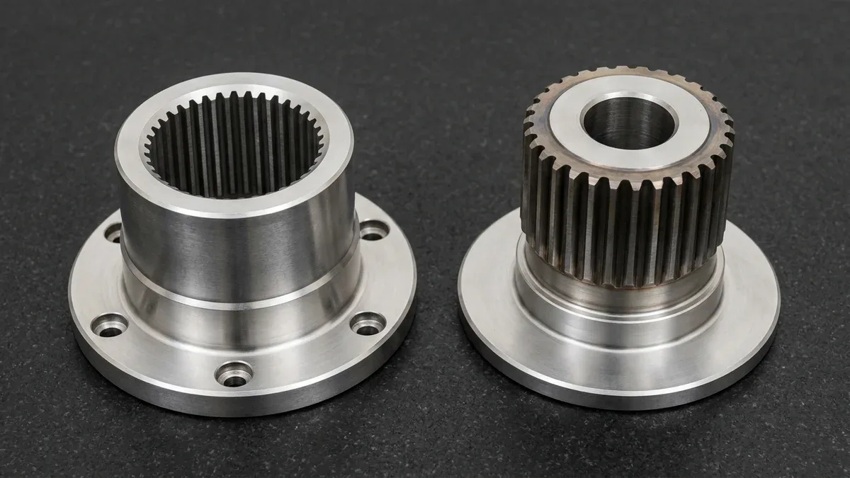
The comparative inspection photograph below illustrates two mating transmission components resting flat on our black granite surface plate: on the left, a flanged 17-4PH stainless steel coupling sleeve featuring six counterbored bolt holes and wire-EDM internal straight-sided spline teeth; on the right, a 42CrMo alloy steel pinion hub featuring hobbed external involute spline teeth and a precision-turned bearing collar.
When external splines terminate flush against a stepped flange or internal splines sit inside a blind bore, CNC power skiving meshes a tilted cutter at a 15° to 25° crossed-axis angle to cut full-depth teeth within a 2.0 mm to 3.5 mm (0.079″ to 0.138″) DIN 509 relief undercut.
Finally, for carburized shafts (58–62 HRC) exhibiting thermal quench unwind, our CNC profile and cylindrical grinding cells dress vitrified CBN wheels to finish-grind spline flanks to ±0.005 mm (±0.0002″) tooth thickness accuracy and Ra 0.2 to 0.4 µm (8 to 16 µin) surface roughness.
| Machining Process | Geometry Capability | Tooth Thickness Tolerance | Surface Roughness (Ra) | Tooling Investment | Recommended Application / When to Choose |
|---|---|---|---|---|---|
| CNC Gear Hobbing | External Only (Needs axial runout) | ±0.010–±0.015 mm (±0.0004″–±0.0006″) | 0.8–1.6 µm (32–63 µin) | Low (Standard module hobs) | Choose for batch production (10–5,000+ pcs) of standard DIN 5480 or ANSI B92.1 external shafts. |
| 4-Axis Milling / Turn-Mill | External Single-Chucking | ±0.010–±0.020 mm (±0.0004″–±0.0008″) | 0.8–1.6 µm (32–63 µin) | Near Zero (Standard end mills) | Choose for rapid prototypes (1–20 pcs) in 4–8 business days (Ex-Factory) or custom non-standard tooth forms. |
| Linear Internal Broaching | Internal Through-Holes Only | ±0.010–±0.015 mm (±0.0004″–±0.0006″) | 0.8–1.6 µm (32–63 µin) | Moderate to High (Broach bar) | Choose for medium-to-high volume through-bore internal hubs in alloy steels ≤ 35 HRC. |
| Submerged Wire EDM | Internal & External Through-Cuts | ±0.005 mm (±0.0002″) | 0.4–0.8 µm (16–32 µin) | Near Zero (Direct CNC wire path) | Choose for prototype internal splines, hardened 58–62 HRC hubs, or thin-walled sleeves. |
| CNC Power Skiving | Internal & External Blind Shoulders | ±0.008–±0.012 mm (±0.0003″–±0.0005″) | 0.6–1.2 µm (24–47 µin) | Moderate (Skiving cutter) | Choose when splines terminate within 2.0–3.5 mm (0.079″–0.138″) of a blind shoulder. |
| CNC Profile Grinding | External Hardened Splines | ±0.005 mm (±0.0002″), DIN Class 4–5 | 0.2–0.4 µm (8–16 µin) | Low to Moderate (Dressed wheel) | Choose to eliminate carburizing distortion on high-speed, zero-backlash hardened shafts. |
4. Metallurgy, Case Hardening & Thermal Distortion Control Protocols
An unhardened carbon steel spline will rapidly suffer adhesive galling, plastic flank indentation, or root fatigue cracking under reversing torque. Pairing the right alloy steel with a controlled thermal hardening process balances a wear-resistant tooth surface (52 to 62 HRC) against a tough, shock-absorbing shaft core (28 to 38 HRC).
- Case-Carburizing Steels (SAE 8620, 9310 & 20CrMnTi): Carburized at 900°C–925°C (1652°F–1697°F) to a 0.8–1.4 mm (0.031″–0.055″) case depth and quenched to 58–62 HRC over a 32–38 HRC core.
- Induction-Hardened Alloy Steels (AISI 4140 / 42CrMo4, 40Cr & 4340): Pre-hardened to 28–34 HRC before hobbing, then contour induction-hardened on the teeth to 52–56 HRC to keep journals un-warped.
- Low-Distortion Plasma Nitriding (4140, 4340 & 38CrMoAl): Processed at 500°C–530°C (932°F–986°F) with zero liquid quench, forming a 500–650 HV case on 4140/4340 (900–1,100 HV on 38CrMoAl, per ASTM E384) and < 0.010 mm (0.0004″) distortion.
- Precipitation-Hardening Stainless Steel (17-4PH Condition H900): Aged at 482°C (900°F) to 40–44 HRC with 1,170 MPa (170 ksi) yield strength and ASTM A967 passivation for corrosive drives.
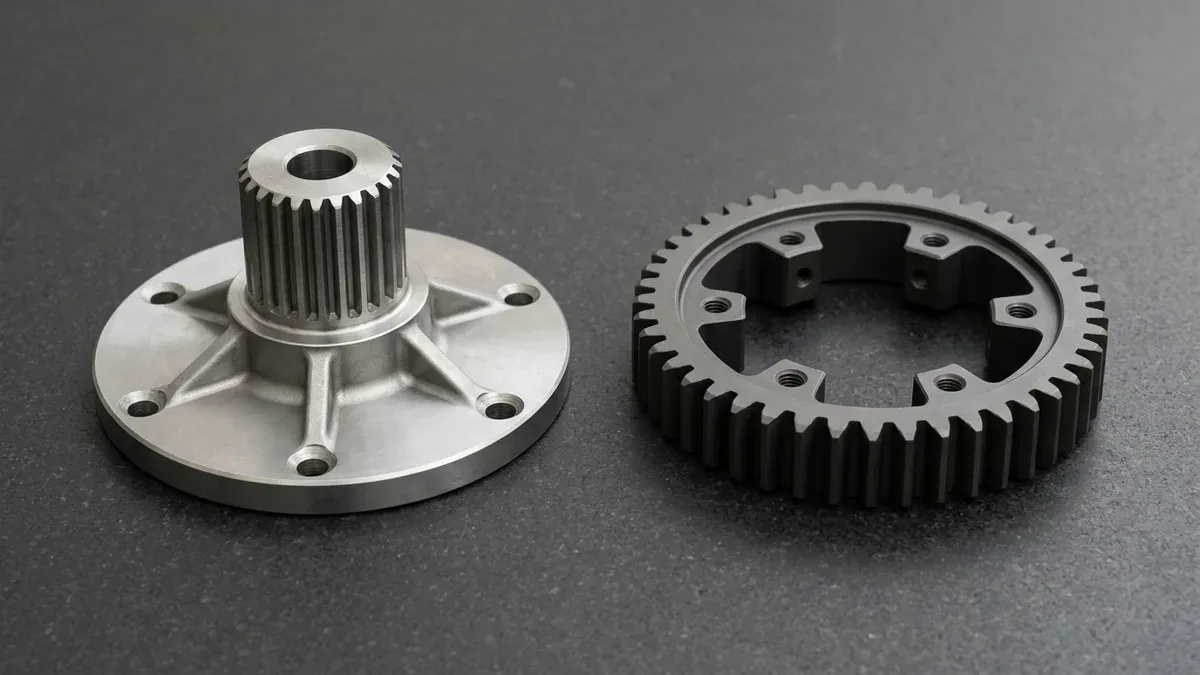
The inspection photograph below shows two heat-treated drivetrain parts resting flat on our black granite plate: on the left, a 4140 steel flanged rotary drive hub featuring six radial stiffening ribs and external involute spline teeth; on the right, a dark gray plasma-nitrided steel ring gear featuring external involute teeth and six inward mounting lugs.
5. 4-Step Shop-Floor SOP for Precision Splined Shaft Manufacturing
Holding total indicator reading (TIR) radial runout within ≤ 0.010 mm (0.0004″) between the spline pitch circle and the supporting bearing journals requires strict datum continuity across turning, gear cutting, heat treating, and finish grinding. Our Shenzhen machine shop executes a standardized four-stage manufacturing workflow on every precision splined shaft lot.
- Execute Single-Chucking CNC Turning & 60° Datum Center Grinding: Rough-turn bar stock leaving 0.25–0.40 mm (0.010″–0.016″) journal grinding allowance, cut DIN 509 relief grooves, and lap 60° center cones at both ends.
- Generate Spline Teeth with Pre-Grind Stock Allowance: Mount the shaft between live centers on a CNC hobber or turn-mill center to cut teeth with +0.06 to +0.10 mm (+0.0024″ to +0.0039″) protuberance grinding stock.
- Perform Vertical Fixture Carburizing or Low-Distortion Nitriding: Suspend slender shafts (L/D > 4:1) vertically inside atmosphere-controlled furnaces to prevent thermal bending sag, followed by ASTM E18 Rockwell hardness verification.
- Lap Center Cones, Finish Grind Journals & Profile Grind Spline Flanks: Lap 60° center cones post-quench, cylindrical-grind journals to ±0.005 mm (±0.0002″), and CNC profile-grind spline flanks on the shared center axis.
6. Over-Pins (M-Dimension) Metrology, GO/NO-GO Gauging & CMM Pitch Verification
Because involute spline torque is transmitted along curved flanks rather than the outer tip diameter, measuring outside diameter with a caliper tells an inspector nothing about tooth thickness or backlash fit. In our 20°C ± 1°C (68°F ± 1.8°F) climate-controlled metrology laboratory, we verify spline accuracy using three progressive inspection methods.
Measurement Over Pins (MOP) for external splines—and Measurement Between Pins (MBP) for internal splines—places two calibrated tungsten carbide pins (dpin ≈ 1.728 × m external or 1.440 × m internal) in opposite tooth spaces so their tangency points contact the pitch circle.
Using a Mitutoyo digital micrometer, inspectors verify the span Meven = db ÷ cos(αe) + dpin (for even tooth count z) or Modd = (db ÷ cos(αe)) × cos(90° ÷ z) + dpin (for odd z), validating effective circular tooth thickness within ±0.010 mm (±0.0004″).
To verify functional fit, we pair sector NO-GO gauges with composite GO spline ring and plug gauges at Maximum Material Condition (MMC). For First Article Inspection (FAI), our on-request Zeiss Contura Bridge CMM scans quadrant teeth for profile error (Fα), lead twist (Fβ), pitch error (Fp), and radial runout (Fr).
| Defect / Failure Mode | Physical Root Cause | Metrological Detection | Recommended Application / When to Choose Corrective DFM Action |
|---|---|---|---|
| Helix Unwind (“Barber-Pole” Twist) | Asymmetric stress release during horizontal quench on shafts with L/D > 5:1. | Fails composite GO ring gauge and CMM lead scan (Fβ). | Use vertical furnace racking plus CNC spline profile grinding, or switch to plasma nitriding. |
| Hob Collision at Shoulder | Spline ends < 2.0 mm (0.079″) from a larger stepped bearing flange. | CAM clash alert or shallow tooth depth near the shoulder. | Add a 5.0–8.0 mm (0.197″–0.315″) hob runout zone, or choose CNC power skiving. |
| Pitch-to-Journal Eccentricity | Re-clamping in a 3-jaw chuck without referencing 60° conical centers. | V-block dial indicator or CMM scan exceeding 0.020 mm (0.0008″) TIR. | Machine soft shafts in one turn-mill chucking, or grind journals and splines on shared centers. |
| Red-Oxide Fretting Corrosion | Uncrowned spline running under > 0.25° angular misalignment. | End-flank gouging and reddish-brown ferric oxide wear debris. | Specify flank crowning (0.020–0.035 mm [0.0008″–0.0014″]) and phosphate or DLC coating. |
| Internal Broach Exit Tear-Out | Missing exit chamfer on ductile stainless or low-carbon steel hubs. | 2.5D optical VMS inspection and GO plug gauge binding at exit. | Turn a 1.0 mm × 45° (0.039″ × 45°) exit chamfer or select submerged Wire EDM. |
7. When NOT to Choose Splined Shafts: Process Limitations & Design Trade-Offs
Although splined connections offer superior torque density, specifying external and internal splines on every rotating joint unnecessarily inflates machining and gauging costs. During pre-production DFM reviews for automotive drivetrain and industrial automation assemblies, our engineers recommend against splined shafts in three specific scenarios:
- Low-Torque Non-Sliding Hubs (< 40 N·m / 29.5 lb·ft): For encoders, fans, or light pulleys without axial sliding, matched splines increase cost by 1.8x to 3.0x over a DIN 6885 single keyway, D-flat, or cross-pinned hub.
- Ultra-High-Fatigue Spindles Requiring Zero Root Notches: Even fillet-root involute splines introduce a notch factor of Kt ≈ 1.4–1.7; for heavy shock spindles, a DIN 32711 (P3G) polygon profile or tapered shrink-disc coupling provides superior fatigue life.
- Dead-Ended Blind Bores Without Undercut Clearance: Neither broaching nor wire EDM cuts dead-ended blind splines, and power skiving requires a 2.0–3.5 mm (0.079″–0.138″) relief groove; otherwise, use a two-piece bolted flange hub.
🔗 Related Shaft Machining & Metallurgy Engineering Guides
8. Technical Engineering FAQ
Specify DIN 5480 or ANSI B92.1 involute splines with a 30° pressure angle for high-torque reversing drivetrains requiring automatic flank self-centering and low root stress concentration. Choose DIN 5462 or ISO 14 parallel straight-sided splines for low-speed sliding hubs centered on a precision-ground minor bore diameter.
Standard CNC gear hobbing and 4-axis index milling maintain general machining tolerances to ISO 2768-mK and over-pins tooth thickness tolerances within ±0.010 mm to ±0.020 mm (±0.0004″ to ±0.0008″). For case-hardened 58 to 62 HRC shafts, CNC profile grinding and submerged wire EDM hold ±0.005 mm (±0.0002″).
Because involute spline torque transmits entirely across curved tooth flanks rather than the outer crest, tip diameter cannot verify effective circular tooth thickness or pitch clearance. Placing two calibrated tungsten carbide pins in diametrically opposite tooth spaces allows micrometer verification of flank thickness within ±0.010 mm (±0.0004″).
Soft-machined prototype splined shafts using 4-axis CNC milling, turn-mill live tooling, or wire EDM require 4 to 8 business days (Ex-Factory). Case-carburized, nitrided, or profile-ground splines require 7 to 12 business days (Ex-Factory), while batches take 7–30 business days (Ex-Factory), excluding 3–5 days air freight.
Ready to Optimize Your Custom Parts for Precision Manufacturing?
Upload your 3D STEP/IGES models and 2D spline table drawings for a comprehensive manufacturability review covering hob runout clearance, heat-treatment distortion control, and over-pins gauging tolerances. Our Shenzhen engineering team will evaluate your external shafts and internal splined hubs to match the most cost-effective machining route to your batch volume.
Request a Technical DFM & Custom Quote →