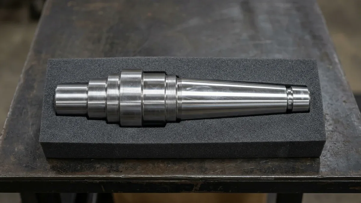
Mastering step turning vs taper turning is essential for hardware teams balancing tight dimensional tolerances, surface integrity, and scalable production economics. In precision CNC turning and rotational machining, shafts, spindles, arbors, and rotating mechanical couplings are the workhorses of mechanical power transmission. Whether engineering an automotive transmission input shaft, an aerospace hydraulic spool, or a precision CNC machine tool spindle, manufacturing engineers continually evaluate two fundamental lathe operations: step turning and taper turning.
While both processes utilize a single-point cutting tool to shear metal from a spinning workpiece held in a lathe chuck or collet, their toolpath kinematics, stress distributions, geometric functions, and inspection methodologies diverge completely. Understanding the nuanced trade-offs between stepped cylindrical transitions and continuous conical tapers is vital for optimizing fatigue life, bearing seating accuracy, and manufacturing cost.
At AS Prototypes, our CNC turning centers, multi-tasking mill-turn machines, and Swiss-type screw lathes manufacture stepped and tapered components held to ±0.010 mm (±0.0004″) CNC turning tolerances—and ±0.005 mm (±0.0002″) via secondary cylindrical grinding. This comprehensive technical guide analyzes the kinematics of step turning vs taper turning, provides the exact mathematical formulas for calculating taper angles and conicity, explores CNC G-code canned turning cycles (G71, G70, G96) and G41/G42 compensation, and delivers practical Design for Manufacturability (DFM) rules for mechanical design engineers.
Executive Summary & Engineering Takeaways (BLUF)
- Kinematic Distinction: Step turning feeds the cutting tool sequentially along orthogonal Z-axis (longitudinal) and X-axis (radial) paths to form discrete cylindrical diameters separated by 90° shoulders, whereas taper turning interpolates X and Z axes simultaneously to generate a continuous conical profile.
- Stress Concentration Mitigation: Sharp internal 90° step shoulders induce severe elastic stress concentration factors (Kt > 2.5); specifying a generous tool-nose fillet radius (r ≥ 0.4 mm to 0.8 mm / 0.016″ to 0.031″) or DIN 509 grinding relief undercut prevents torsional fatigue failure.
- G41/G42 Cutter Compensation: Because carbide turning inserts possess a finite nose radius (typically 0.4 mm or 0.8 mm), programming conical tapers requires active G41/G42 tool-nose radius compensation to eliminate radial over-sizing (ΔR = rε[1 − cos θ]) and axial transition shifts.
- Achievable Turning & Grinding Precision: Multi-axis CNC turning centers hold diameter tolerances of ±0.010 mm (±0.0004″) and surface finishes of Ra 0.8 μm (32 μin), while secondary cylindrical grinding achieves ±0.005 mm (±0.0002″) and Ra 0.2 μm (8 μin) on critical tapers.
Article Engineering Navigation
- 1. What is Step Turning? Kinematics & Mechanics
- 2. Stress Concentrations in Stepped Shafts: The Shoulder Radius
- 3. What is Taper Turning? Kinematics & Conical Geometry
- 4. Mathematical Formulations & Taper Calculations
- 5. Step Turning vs Taper Turning: Engineering Comparison Matrix
- 6. CNC Programming & Tool Nose Radius Compensation (G41/G42)
- 7. Metrology & Quality Verification of Stepped vs Tapered Parts
- 8. Design for Manufacturing (DFM) Guidelines for Turning
- 9. Technical Engineering FAQ
1. What is Step Turning? Kinematics & Mechanics
Step turning is a rotational machining process that creates two or more distinct cylindrical sections of varying diameters along the longitudinal axis of a single workpiece, separated by perpendicular or filleted shoulders.
Kinematics and Tool Movement
In step turning, the primary cutting motion occurs strictly along a single axis at any given moment:
- Longitudinal Feed (Z-Axis): The cutting tool traverses parallel to the rotating axis of the spindle, producing a perfectly cylindrical journal of constant diameter.
- Radial Infeed (X-Axis): The cross slide feeds perpendicular to the workpiece axis to set the depth of cut for the next diameter, or retracts across the shoulder face.
Engineering Purpose & Function
Stepped shafts are ubiquitous in mechanical engineering because they provide precise positive axial locating stops for mounted mechanical elements:
- Bearing Journals & Locating Shoulders: Ground cylindrical steps receive rolling-element ball and roller bearing inner rings (e.g., ISO j5, k6, or m6 bearing journal transition/interference fits, and h6 for precision locating seats), while the perpendicular shoulder arrests axial thrust loads.
- Gear and Pulley Mounting: Stepped diameters allow splined gears, timing pulleys, and keyways to slide freely over smaller lead diameters before seating rigidly on their functional mating diameter.
- Retaining Ring & Seal Lands: Stepped shafts incorporate grooved steps for external snap rings (circlips) and mirror-finished lands for elastomeric rotary shaft lip seals.
2. Stress Concentrations in Stepped Shafts: The Shoulder Radius
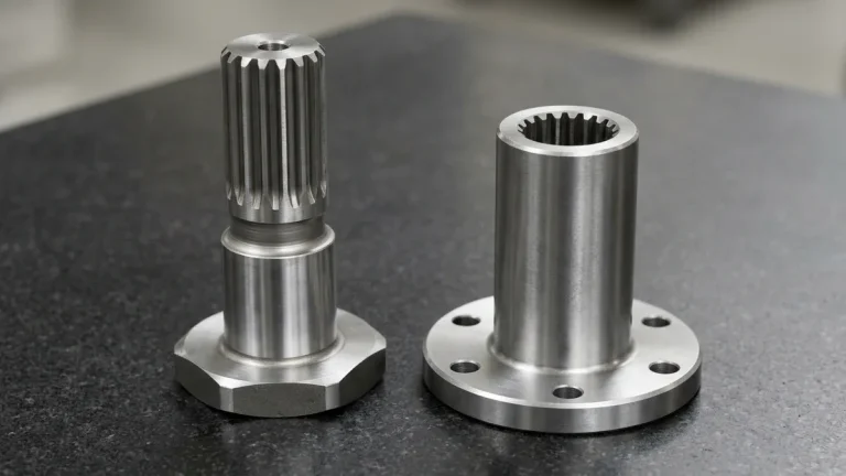
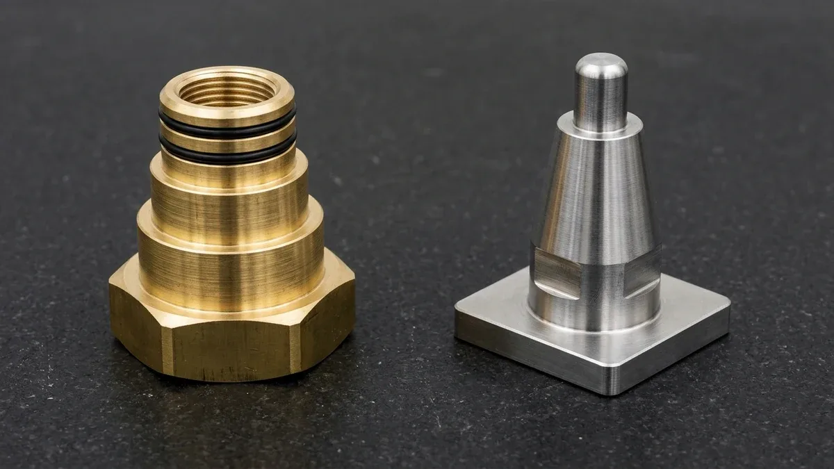
As illustrated in Figure 1, orthogonal step turning and synchronized two-axis taper interpolation produce fundamentally different shoulder transitions on rotational hardware. The C3604 brass hydraulic fitting on the left features crisp 90-degree stepped lands with relief undercuts, whereas the 17-4PH stainless steel valve spindle on the right exhibits a continuous 15-degree conical taper.
The primary engineering vulnerability of a stepped shaft is the stress concentration factor (Kt) at the 90° internal shoulder transition. Under cyclic torsional moments and rotating-bending fatigue, an abrupt, razor-sharp inside corner concentrates mechanical stress lines, serving as the prime nucleation site for fatigue fracture.
Mitigating Stress Concentration at Shoulders
- Transition Fillet Radius (r): Designing a generous fillet radius at the base of the shoulder drastically flattens the stress gradient (Kt drops from > 3.0 with a sharp corner to < 1.5 with r/d ≥ 0.1). However, the fillet radius must be smaller than the corner chamfer of the mating bearing to ensure the bearing inner ring seats completely flat against the vertical shoulder face.
- Undercut Relief Grooves (DIN 509 Form E & Form F): When a mating component requires a sharp, flat seating shoulder without interference from a radius, engineers specify a standardized grinding undercut (relief groove). This relieves internal corner stress while providing clearance for subsequent cylindrical OD grinding wheels.
3. What is Taper Turning? Kinematics & Conical Geometry
Taper turning is a rotational machining process that generates a uniform, gradual change in diameter along the length of a cylindrical workpiece, forming a true truncated cone. Tapers can be external (male conical shanks) or internal (female conical sockets and collet seats).
Kinematics and Simultaneous 2-Axis Interpolation
Unlike step turning where axes move independently, modern CNC taper turning requires simultaneous, synchronized interpolation across both the X-axis (diameter) and Z-axis (length). The cutting tool moves at a continuous, oblique angle relative to the center line of the spindle, continuously altering the workpiece diameter at a constant mathematical slope.
Engineering Purpose & Function
Conical tapers possess unique mechanical attributes that cylindrical steps cannot duplicate:
- Zero-Backlash Concentric Alignment: When a male taper engages a matching female conical bore, the wedging action automatically aligns their central axes with near-zero radial runout (±0.005 mm), regardless of slight axial tolerances.
- High Torque Transmission via Frictional Wedging: Steep self-releasing tapers (7:24 ISO/CAT/BT) and shallow self-holding tapers (Morse Taper MT1–MT6) transmit massive torsional loads through high normal interface contact pressure without requiring drive keys.
- Rapid Disassembly without Galling: In self-releasing tapers, an axial displacement of only a few tenths of a millimeter completely releases all circumferential contact pressure, allowing instantaneous toolholder extraction without surface scuffing.
- Leak-Free Fluidic Sealing: Metal-to-metal conical seats are the foundation of high-pressure hydraulic flare fittings, needle valve seats, and tapered pipe threads (NPT / BSPT).
4. Mathematical Formulations & Taper Calculations
Calculating a taper requires precise trigonometry to determine the toolpath angle (θ), conicity ratio (K), and CNC coordinate endpoints:
Core Variables:
- D = Major diameter at the large end of the taper (mm)
- d = Minor diameter at the small end of the taper (mm)
- L = Axial length of the tapered section (mm)
- θ = Half-taper angle (the angle between the tapered surface and the centerline)
- α = Included full taper angle (α = 2θ)
- K = Conicity ratio
1. Conicity Ratio (K)
Example: A standard Morse Taper #3 has a conicity of approximately 1:19.922 (0.05020 mm/mm).
2. Half-Taper Angle (θ) Calculation
3. Manual Lathe Tailstock Offset (S)
When turning shallow tapers on a manual engine lathe by offsetting the tailstock center:
Where Ltotal is the total length of the entire shaft held between centers.
5. Step Turning vs Taper Turning: Engineering Comparison Matrix
The following engineering matrix contrasts the critical technical parameters of step turning vs taper turning across kinematics, CNC programming, tooling, and metrology:
| Technical Attribute | Step Turning (Stepped Shafts) | Taper Turning (Conical Profiles) |
|---|---|---|
| Workpiece Geometry | Discrete cylindrical sections of uniform diameter joined by perpendicular 90° shoulders. | Continuous conical surface where diameter varies linearly or curvilinearly along axial length. |
| Tool Kinematics | Single-axis independent feed: Longitudinal Z-axis for cylinders, radial X-axis for shoulders. | Simultaneous 2-axis coordinated linear interpolation across both X and Z axes. |
| Primary Mechanical Role | Axial positioning stops, bearing journal seats, gear/pulley retention, and seal lands. | Self-centering zero-backlash alignment, high-torque wedging transmission, and fluid sealing. |
| Stress Concentrations | High notch sensitivity at sharp shoulders; demands transition fillets (r) or DIN 509 undercuts. | Smooth, gradual stress distribution; virtually zero localized stress concentration along the cone. |
| CNC G-Code Execution | Standard G71 roughing canned cycle, G70 finish cycle, constant surface speed (G96). | Interpolated G01 X… Z… linear moves or G71 Type II roughing cycle with mandatory G41/G42 tool nose radius compensation. |
| Manual Lathe Execution | Straightforward carriage feed with cross-slide stops; simple setup on conventional engine lathes. | Requires compound rest swiveling (short tapers), tailstock offset (shallow tapers), or taper attachments. |
| Metrology & Inspection | Outside micrometers, optical shaft comparators, height gages with dial test indicators for shoulder runout. | Sine bars with slip gauge stacks, master taper ring/plug gages with Prussian Blue (contact ≥ 85%), or air gages. |
| Typical Components | Automotive axles, gearbox input shafts, pump shafts, motor rotors, multi-stage spool valves. | Morse taper drill shanks, CAT40/BT50 toolholders, ER collet chucks, tapered roller bearings, valve plugs. |
6. CNC Programming & Tool Nose Radius Compensation (G41/G42)
In modern CNC turning centers, executing step turning vs taper turning highlights the crucial role of CNC tool geometry management:
Step Turning Canned Cycles (G71 / G70)
To remove bulk stock on stepped shafts, programmers utilize the standard G71 2-line rough turning cycle. The CNC control automatically calculates successive longitudinal passes, stepping back from the finished profile. Because cutting occurs strictly parallel or perpendicular to machine axes, tool nose radius compensation does not alter straight diameters, though it determines the final corner fillet radius.
The Critical Imperative of G41 / G42 in Taper Turning
Unlike cylindrical turning, when a lathe tool turns an inclined taper angle, the theoretical tool tip (which CAM software uses to program X and Z coordinates) does not touch the workpiece. Instead, cutting occurs along the tangent of the circular tool nose radius (rε, typically 0.4 mm or 0.8 mm).
If tool nose radius compensation is neglected:
- The machined taper angle will be mathematically distorted, causing steep slope errors.
- The workpiece will be left oversized on external tapers and undersized on internal tapers.
The Solution: CNC programs must invoke G42 (cutter compensation right) for external turning toward the chuck, accompanied by proper tool quadrant declaration (Tool Tip Direction 3 for OD turning tools) in the CNC tool geometry register.
7. Metrology & Quality Verification of Stepped vs Tapered Parts
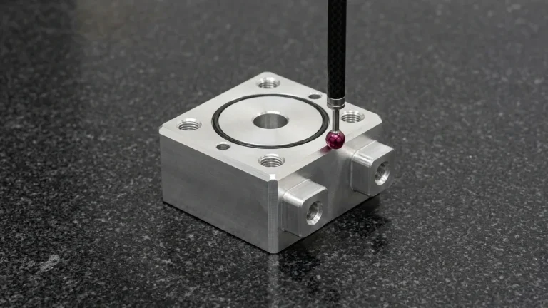
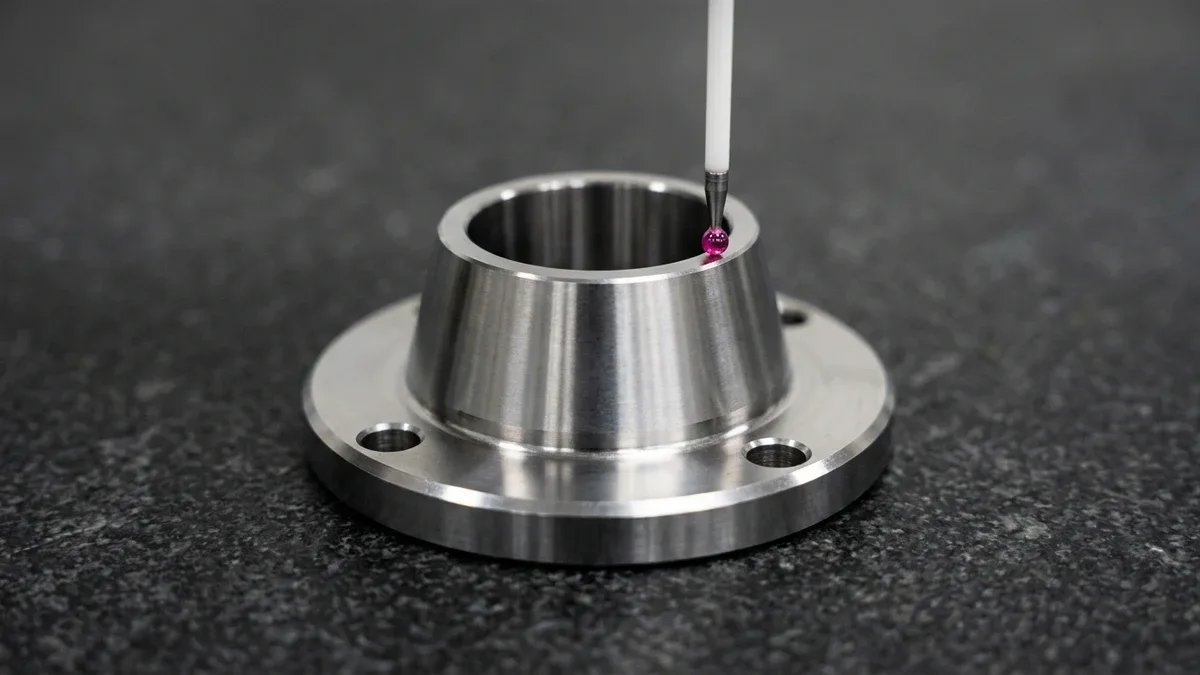
To verify angular accuracy after dual-axis lathe interpolation, Figure 2 shows a vertical CMM ruby stylus probing the 15-degree external conical taper and flange concentricity of a CNC-turned 17-4PH stainless steel adapter sleeve on black granite. Multi-height coordinate sampling confirms that taper rate and coaxiality remain within tight assembly limits.
Quality assurance protocols differ significantly between stepped and conical geometries:
1. Stepped Shaft Verification
- Diametral Accuracy: Digital outside micrometers and snap gages inspect individual journal diameters to tight ISO tolerances (e.g., h6, j6, k6).
- Shoulder Perpendicularity & Axial Runout: Workpiece mounted between precision dead centers while a lever-type dial test indicator (DTI, 0.005 mm resolution) measures total indicator reading (TIR) against the vertical shoulder as the shaft rotates.
- Fillet Radii & Undercuts: Optical profile comparators and shadowgraphs verify radius continuity without chatter gouges.
2. Tapered Shaft Verification
- Sine Bar & Slip Gauge Stacks: The ultimate metrological baseline. The taper angle is verified on a granite surface plate by resting the tapered shaft onto a calibrated sine bar elevated by precision ceramic gauge blocks (H = L · sin(θ)). A dial indicator swept along the upper apex must read zero deviation.
- Prussian Blue Dye Contact Checks: The male taper is coated with a microscopic film of Prussian Blue and inserted into a verified master taper ring gage. Standards mandate a minimum 80% – 90% uniform surface contact pattern without edge binding.
- Pneumatic Air Gages: For high-volume production of automotive and aerospace tapers, dual-channel pneumatic air ring gages measure diameter at two axial planes simultaneously, displaying instant digital conicity readings down to 0.1 μ m.
8. Design for Manufacturing (DFM) Guidelines for Turning
Incorporate these battle-tested DFM guidelines into your CAD modeling to reduce machining cycle times and avoid costly tooling rework:
1. Standardize Taper Angles (Avoid Arbitrary Decimals)
Whenever designing conical fits, always specify standardized taper classifications—such as Morse Taper (ISO 296), 7:24 Steep Taper (ISO 7388 / ASME B5.50), HSK 1:10 (ISO 12164), or standard 1:10 / 1:20 metric tapers. Specifying standard tapers enables machine shops to utilize off-the-shelf master ring and plug gauges, avoiding custom-ground inspection tooling costs.
2. Design Consistent Shoulder Undercuts
When multiple bearing seats exist on a stepped shaft, specify uniform DIN 509 relief groove dimensions across all steps. This allows the CNC lathe tool turret to utilize a single grooving insert for all undercuts without tool indexing.
3. Manage Length-to-Diameter Ratios (L/D)
Turning long, slender shafts where L/D > 4 causes intense cutting deflection and chatter under tool radial forces. For shafts exceeding L/D = 4, engineers must allow for a centered tailstock live center drill point; for L/D > 8, design clearance zones for steady rests or follow rests.
4. Sequence Diameters Progressively
Design stepped shafts with diameters that decrease monotonically from the center toward the shaft ends. This enables continuous single-setup turning and simplifies grinding wheel clearances.
🔗 Related CNC Turning & Shaft Engineering Guides
9. Technical Engineering FAQ
Modern CNC turning centers hold conical half-angles within ±0.01° across production batches using simultaneous X–Z linear interpolation, whereas manual compound-rest setups suffer from angular drift. Active G41/G42 tool nose radius compensation is mandatory to eliminate profile undercut errors along the tapered flank.
Precision CNC turning holds ±0.010 mm tolerances and Ra 0.8 µm roughness, while post-quench cylindrical grinding achieves ±0.005 mm roundness and Ra 0.2 µm on 58–62 HRC shafts. Specify a DIN 509 relief undercut at each step shoulder so grinding wheels clear corners cleanly.
Self-holding Morse and Jacobs tapers use shallow 1.4°–3.0° included angles to lock via radial wedging friction, whereas self-releasing 7:24 spindle tapers use a steep 16.59° angle. Steep tapers require an active drawbar pull force to maintain rigidity while releasing cleanly during automatic tool changes.
Unsupported shafts above a 6×D slenderness ratio deflect radially under cutting loads, causing diametral taper error and chatter exceeding Ra 3.2 µm. We eliminate deflection using a live tailstock center, cutting toward the chuck with 0.4 mm nose-radius inserts, or running Swiss guide bushings.
Ready to Validate Your CAD Design for Precision Manufacturing?
Upload your 3D CAD models (STEP, IGES, SolidWorks) and 2D engineering drawings for a comprehensive DFM engineering review and custom quotation from our in-house CNC machining and prototyping team.
Request a Custom DFM Review & Quote →