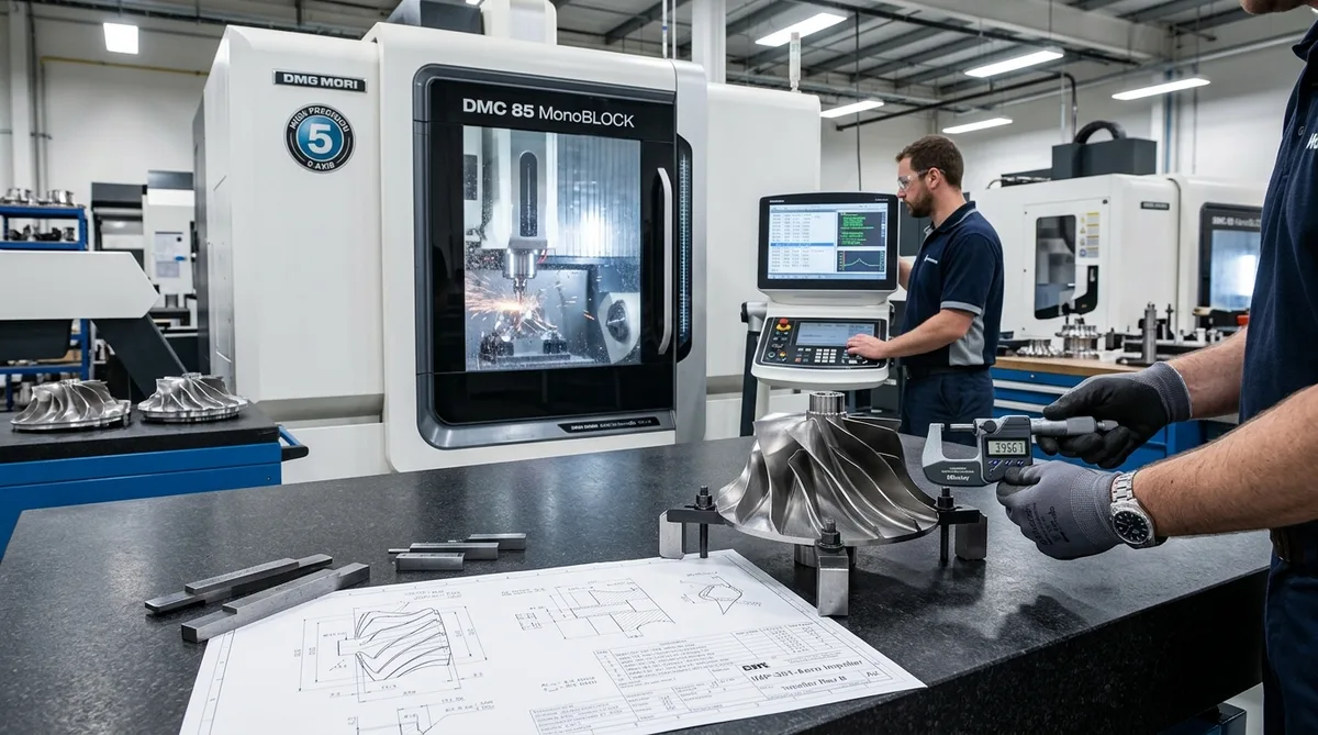
Mastering modern CNC precision engineering is the backbone of mission-critical hardware development, dictating how digital 3D solid models are translated into micron-accurate physical components. Across aerospace turbomachinery, surgical robotics, and high-pressure fluid manifolds, precision engineering bridges computational CAM toolpaths with the rigorous thermodynamics of metal cutting. At our in-house machine shop, our manufacturing engineers integrate advanced precision CNC machining workflows with multi-axis 5-axis simultaneous machining and Zeiss CMM metrology to execute complex geometries with sub-5-micron repeatability.
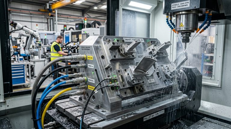
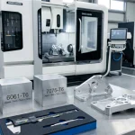
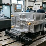
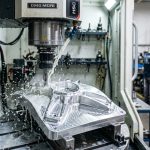
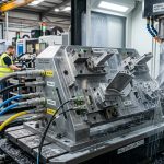
Precision CNC engineering workflow: 5-axis DMG MORI monoBLOCK machining center cutting a titanium impeller, with engineering blueprint analysis and digital micrometer verification on a granite surface plate.
The Core Disciplines of Precision Subtractive Manufacturing
Precision CNC engineering differs fundamentally from standard commercial machining through its rigorous control over thermal expansion, dynamic cutting vibration, and geometric dimensioning. Achieving dimensional tolerances as tight as ±0.005 mm (0.0002 inches) requires synchronizing every phase of the manufacturing chain—from initial model hygiene and kinematic simulation to rigid fixture mechanics and metrology auditing.
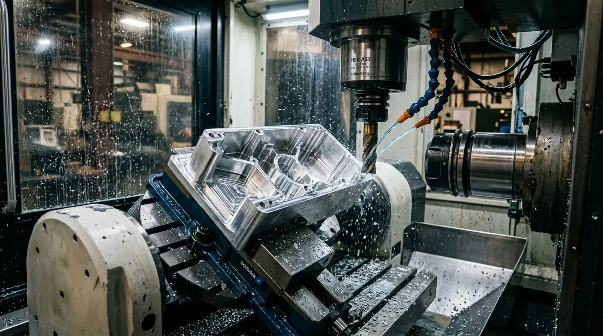
Phase 1: 3D CAD Geometry & GD&T Engineering Review
Precision execution starts with a deep dive into the part’s geometric definition:
- Datum Scheme Establishment: Defining functional primary, secondary, and tertiary datums per ASME Y14.5 or ISO 1101 ensures that machining setups match the real-world assembly constraints.
- True Position & MMC Modifiers: Applying Maximum Material Condition (MMC) modifiers to fastener patterns provides maximum manufacturing tolerance bonus without compromising fit.
- DFM Corner Reliefs & Wall Ratios: Verifying internal pocket radii match standard milling tools (R ≥ 1.5 mm) prevents tool chatter and expensive micro-cutter passes.
Phase 2: Advanced CAM Toolpathing & Kinematic G-Code Simulation
Modern CAM programming optimizes cutting force equilibrium and eliminates cycle bottlenecks:
- Trochoidal High-Efficiency Milling (HEM): By maintaining a constant radial cutter engagement angle (θ ≤ 30°), HEM enables high axial depths of cut at elevated feed rates, distributing wear across the entire flute length rather than concentrating friction on the tool tip.
- 5-Axis Simultaneous Swarf Profiling: Machining complex aerodynamic blades or impeller vanes using the side of the endmill rather than point contact dramatically reduces cycle times while achieving surface roughness Ra < 0.4 μm.
- Digital Twin Collision Avoidance: Simulating full machine kinematics—including trunnion rotary limits, spindle interference envelopes, and chuck bolt clearances—guarantees error-free first-article runs.
Phase 3: Machine Tool Setup, Zero-Point Clamping & Thermal Control
Rigid workholding and thermal stability dictate repeatable precision:
- Modular Zero-Point Clamping: Standardized pneumatic chucks position fixtures with repeatability within ±0.002 mm, allowing seamless transfer between 3-axis roughing and 5-axis finish machines.
- Laser Spindle Tool Setting: Non-contact Blum laser tool setters measure tool lengths, diameters, and runout at operational RPM, dynamically updating tool registers to compensate for centrifugal thermal growth.
- Climate-Controlled Facility: Machining centers operate in an enclosed, temperature-regulated environment (20°C ± 1°C) to prevent thermal dimensional drift during long multi-hour finishing cycles.
Precision Engineering Lifecycle & Quality Gate Matrix
The operational framework below details how each phase of the CNC precision engineering lifecycle is executed and verified:
| Workflow Phase | Hardware / Software Infrastructure | Critical Parameter Target | Quality Verification Gate |
|---|---|---|---|
| 1. Design for Machining | SolidWorks / CATIA CAD | Aspect ratio ≤ 4:1; draft ≥ 1° | Automated DFM manufacturability check |
| 2. CAM Kinematics | Siemens NX / HyperMill | Constant chip load; 0 collision risk | G-code digital twin verification |
| 3. Machine Setup | Lang Zero-Point / Gerardi Vises | Pallet repeatability ±0.002 mm | Renishaw touch probe datum audit |
| 4. Precision Cutting | DMG MORI / Makino 5-Axis (24K RPM) | Bore tolerance ±0.005 mm | Laser tool wear compensation |
| 5. Final Metrology | Zeiss Contura CMM + Ruby Stylus | Volumetric accuracy 1.5 + L/350 μm | FAIR (First Article Inspection Report) |
Precision Machinability Benchmark: Aluminum, Stainless, Titanium & Plastics
Different alloy structures require tailored speeds, feeds, and coolant strategies:
| Material Family | Benchmark Grade | Machinability Index (%) | Cutting Speed Vc (m/min) | Standard Precision Tolerance |
|---|---|---|---|---|
| Aerospace Aluminum | 6061-T6 / 7075-T6 | 360 % (Free Cutting) | 400 – 1,200 m/min | ±0.005 mm |
| Austenitic Stainless | 304 / 316L Stainless | 45 % (Work Hardening) | 100 – 180 m/min | ±0.010 mm |
| Titanium Alloy | Ti-6Al-4V (Grade 5) | 22 % (Low Conductivity) | 45 – 80 m/min (High Pressure Coolant) | ±0.008 mm |
| Tool Steel | S136 / H13 (Hardened 52 HRC) | 30 % (Abrasive Hardened) | 60 – 120 m/min (CBN / TiAlN) | ±0.005 mm |
| Engineering Polymer | Delrin POM-C / PEEK | 280 % (Low Modulus) | 250 – 500 m/min (Sharp Polished) | ±0.015 mm |
Phase 4: CMM Metrology & First Article Inspection (FAIR)
Precision engineering is incomplete without empirical metrology documentation:
- Bridge-Type Coordinate Measuring Machine (CMM): Utilizing ruby-tipped scanning probes in an active climate lab, our Zeiss CMM captures 3D coordinate clouds to audit true position, profile runout, and concentricity against the native CAD model.
- Optical Surface Roughness Profilometry: Verifies that critical bearing journals and dynamic O-ring seals meet Ra 0.4 to 0.8 μm specifications without micro-chatter marks.
- First Article Inspection Reports: Every dimension flagged on customer 2D prints is numbered with balloon drawings and reported with actual measured values and pass/fail criteria.
Metals expand and contract with temperature changes. Aluminum has a thermal expansion coefficient of approximately 23 µm per meter per °C. In a 300 mm part, a 5°C temperature swing causes over 0.034 mm of dimensional drift. Operating in a strictly climate-controlled facility at 20°C ± 1°C is mandatory for holding sub-0.01 mm tolerances.
3-axis machines move along X, Y, and Z simultaneously. 3+2 axis machining positions the tool at fixed compound tilt angles using rotary axes before executing 3-axis toolpaths. Continuous 5-axis machining moves all five axes simultaneously, enabling the cutter to maintain optimal tangent contact across complex aerodynamic and organic freeform contours.
Climb milling (down milling) engages the cutting edge at maximum chip thickness and tapers to zero at exit, pulling the workpiece toward the fixture. This minimizes tool deflection, prevents chatter, and produces superior surface finishes compared to conventional milling, which rubs and work-hardens the surface upon entry.
Launch Your Precision CNC Engineering Project
Partner with our experienced engineering team for high-precision 5-axis CNC milling, turning, and metrology inspection. Submit your 3D CAD models (STEP / IGES) and 2D technical drawings today for an instant DFM manufacturability evaluation and detailed quotation.
Upload CAD Drawings for Engineering Review →