

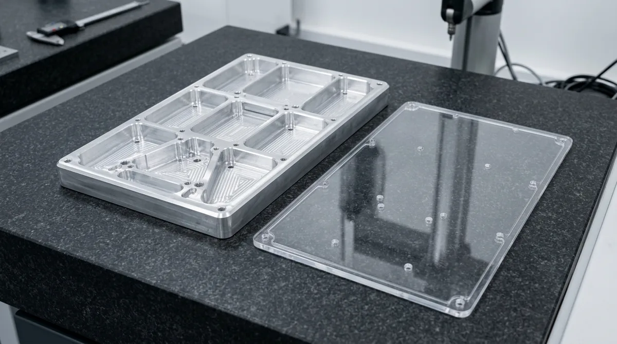
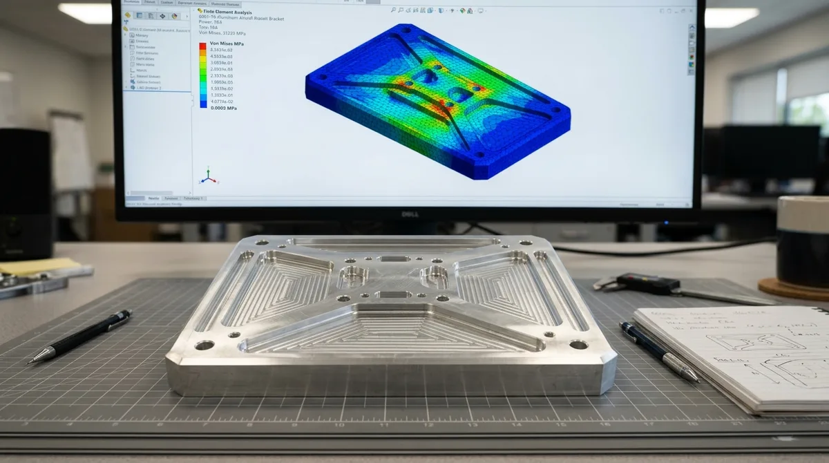
Evaluating physical prototypes remains the ultimate engineering truth-test in modern product design, bridging the critical divide between digital 3D models and real-world physical behavior. While finite element analysis (FEA) and computational fluid dynamics (CFD) offer powerful predictive guidance, they cannot fully simulate real-world machining clamping stresses, micro-defects, thermal boundary resistance, or human tactile perception. At our in-house machine shop and metrology facility, we produce precision prototypes via precision CNC machining and polyurethane vacuum casting to ensure thorough design verification prior to hard tooling release.
- Core Focus & DFM Scope: Actionable shop-floor engineering guidelines for physical prototypes evaluation, covering material selection, geometric tolerancing, and defect prevention.
- Achievable Tolerance Envelope: General features hold ISO 2768-mK; critical bearing bores, dowel pins, and mating datums hold ±0.010 to ±0.020 mm (±0.0004″ to ±0.0008″), with Wire EDM/grinding to ±0.005 mm (±0.0002″).
- Machining & Surface Integrity: High-speed 3-axis and 4-axis VMCs (with simultaneous 5-axis for complex contours) delivering as-machined Ra 0.8 µm (32 µin) to Ra 0.4 µm (16 µin) per ASME B46.1.
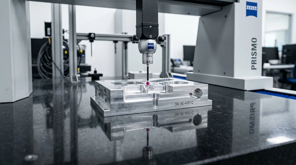
- Metrology & Process Control: On-machine spindle probing paired with 20°C (68°F) climate-controlled Zeiss CMM coordinate verification and calibrated Go/No-Go plug/ring gauges.
- Ex-Factory Turnaround: 4 to 8 business days for as-machined rapid prototypes; 7 to 12 business days for anodized, plated, or multi-operation production runs (excluding 3–5 days air transit).
1. Pillar 1: Geometric & Dimensional Metrology (GD&T Verification)
The primary objective of any initial prototype run is dimensional fidelity. Digital CAD models exist in an idealized mathematical universe with zero clearance errors, perfectly parallel planes, and flawless concentricity. In reality, physical components must abide by the laws of thermodynamics, material stress relaxation, and cutting tool deflection.
To establish empirical ground truth, our quality inspection department employs a multi-tier metrology protocol:
- Coordinate Measuring Machine (CMM) Verification: Critical functional datums, hole pitch diameters, and perpendicularity callouts are measured using high-precision CNC bridge coordinate measuring machines in a temperature-controlled metrology lab (20±0.5°C). Contact ruby styluses verify tolerances down to sub-ten-micron (±0.005 mm) thresholds for bearing press-fit journals and dowel pin centerlines upon request.
- 2.5D Optical Vision Measuring Systems (VMS): For complex sculpted surfaces, ergonomic housings, and aerodynamic impellers, non-contact 2.5D optical vision measuring systems (VMS) capture millions of surface coordinate points. The resulting point cloud is superimposed directly onto the nominal STEP model to generate 3D chromatic deviation heatmaps, identifying localized sinkage or tool deflection.
- Surface Roughness Profilometry: Contact stylus profilometers verify critical seal gland surfaces and sliding bearing tracks against engineering roughness callouts, ensuring compliance from Ra 0.4 μm ground finishes to Ra 3.2 μm bead-blasted cosmetic textures according to ISO 2768-mK general tolerances and drawing-specified precision tolerances.
2. Pillar 2: Functional Kinematics, Mechanical Stress & Environmental Integrity
A prototype that measures within nominal tolerance on a CMM granite table can still fail under dynamic operational loading. Pillar 2 evaluates how components perform when subjected to multi-axial forces, torque transmission, cyclical vibrations, and environmental temperature shifts.
Key physical stress and kinematic validation protocols include:
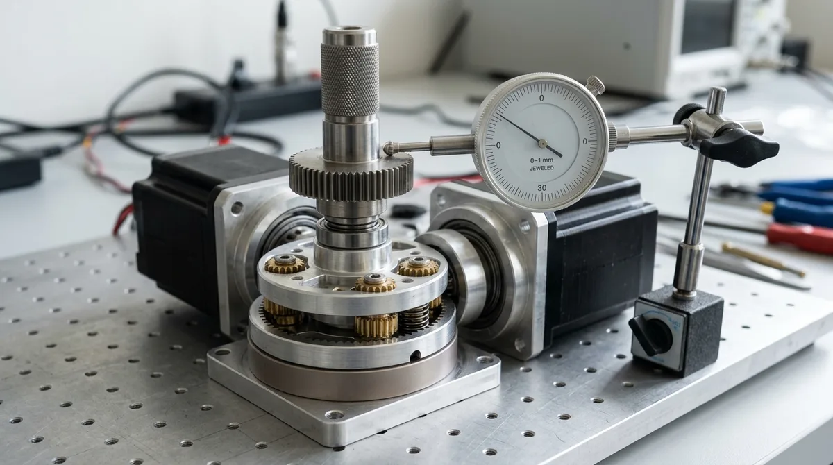
- Dynamic Tolerance Stack-Up & Gear Backlash: In multi-component assemblies—such as planetary gearboxes, optical gimbal mechanisms, and robotic joints—manufacturing variations accumulate. Physical prototypes reveal gear mesh binding, excessive backlash, and friction-induced thermal expansion that cannot be uncovered in static CAD interference checks.
- Differential Thermal Expansion (CTE Mismatch): When dissimilar materials are fastened together (e.g., an aluminum 6061-T6 housing with a thermal expansion coefficient of 23 μm/(m·K) mated to a 304 stainless steel shaft at 17 μm/(m·K)), thermal chamber testing (-40°C to +85°C) exposes interface binding, joint loosening, and gasket seal leaks.
- Destructive Retention & Pull-Out Testing: Threaded brass inserts, press-fit dowels, and welded joints undergo calibrated tensile and torque-to-failure testing to verify that real-world assembly retention exceeds required engineering safety margins.
3. Pillar 3: Human Ergonomics, Assembly Fit & Tactile HMI Perception
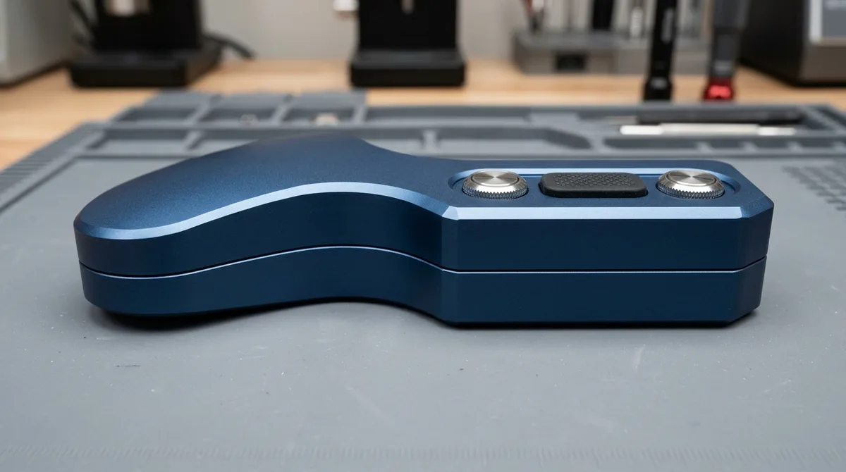
The third critical pillar addresses human interaction, assembly line manufacturability, and cosmetic surface perception. Regardless of virtual reality or digital rendering sophistication, human tactile perception is extraordinarily sensitive to micro-steps across split lines, sharp edge burrs, and unbalanced weight distribution.
Ergonomic and cosmetic prototype evaluation focuses on three core dimensions:
- Tactile Haptics & Actuation Dynamics: Tactile feedback for mechanical switches, membrane buttons, and rotary dials is validated for actuation resistance (typically 3.0 to 5.0 N), travel click ratio, and return spring damping to guarantee an intuitive user experience.
- Enclosure Split-Line & Seam Gap Alignment: Multi-part plastic or aluminum enclosures are evaluated for uniform parting seam gaps (±0.05 mm tolerance) and flushness steps across mating bezels, preventing light leaks, creaking, or uncomfortable pinch points.
- Surface Finish & Color Match (CMF): Physical samples are inspected under standardized D65 daylight viewing booths to verify specular gloss levels, bead blast consistency (#100 to #150 glass bead), Type II/III color anodizing tint matching, and laser-engraved graphic legibility.
4. Evaluation Framework: Digital Simulation vs. Physical Rapid Prototyping
To establish an optimal product verification strategy, engineering teams must recognize the complementary roles of computational simulations and empirical physical prototypes. While software modeling drastically narrows design iterations, physical hardware testing remains irreplaceable for validating non-linear real-world behavior.
| Evaluation Dimension | Digital Simulation (FEA / CFD) | Physical Prototype Testing | Core Engineering Risk Mitigated |
|---|---|---|---|
| Geometric Stack-up | 1D/3D statistical stack software models idealized bounds | Measures actual machined part variations & clamping strain | Eliminates unexpected binding in multi-part assemblies |
| Material Microstructure | Assumes homogeneous, isotropic bulk material values | Exposes grain orientation, weld lines, and internal porosity | Prevents catastrophic shear failure at hidden stress risers |
| Dynamic Friction & Wear | Relies on theoretical static friction coefficients (μ) | Empirical endurance cycling under real lubrication & dust | Validates motor torque margins and seal degradation rates |
| Ergonomics & Tactile HMI | VR/Renderings evaluate visual proportions only | Direct user hand testing, button click feel, weight balance | Prevents costly post-tooling aesthetic and ergonomic redesigns |
Measurement Repeatability and Sample Size in Prototype Evaluation
Physical prototype evaluation is only as reliable as its measurement system, so gauge repeatability should consume no more than about 10 percent of the tolerance band before pass or fail decisions are made.
- Gauge repeatability: A repeatability study with several operators and parts shows how much of the tolerance band is used by the gauge itself, with results between 10 and 30 percent considered marginal and above 30 percent unsuitable.
- Sample size: Measure three to five parts per configuration rather than a single unit, so process variation and design trends can be separated with reasonable confidence.
- Environmental conditioning: Stabilize parts at 20°C for about 24 hours before measurement, because aluminum grows about 0.023 mm per 100 mm for every 10°C of temperature change.
- Reporting method: Report measured values together with the instrument used and its resolution, rather than pass or fail marks, so later builds can be compared directly.
Building these controls into the evaluation process makes prototype results repeatable between teams and suppliers, and it keeps decisions about design changes based on data that can be reproduced when the program scales.
Why Do Physical Prototypes Evaluation Components Fail Tight Tolerances in Production, and How Do You Prevent It?
Maintaining repeatable accuracy in physical prototypes evaluation requires controlling radial tool deflection, internal residual stress relaxation, and thermal expansion drift across multi-axis setups. While general unmated features reliably conform to ISO 2768-mK, holding critical mating bores and datum surfaces within ±0.010 mm (±0.0004″) demands staged roughing-to-finishing stress relief and rigid workholding.
Shop-Floor Quantitative Derivation: Cantilever Tool Deflection & Thermal Drift Compensation
In our Shenzhen CNC machine shop, preventing wall taper and bore bell-mouthing in physical prototypes evaluation begins with calculating cantilever end-mill deflection (δ) before releasing G-code to the spindle. Modeled as a cylindrical carbide beam of diameter D and stickout length L subjected to radial cutting force Fr, tool deflection follows the fourth-power stiffness law:
δ = (64 × Fr × L³) / (3 × π × E × D⁴)
For a solid carbide end mill (E = 600 GPa / 87,000 ksi) with diameter D = 8.0 mm (0.315″), stickout L = 36 mm (4.5×D), and radial cutting load Fr = 180 N (40.5 lbf), the resulting deflection is δ = (64 × 180 × 36³) / (3 × 3.1416 × 600,000 × 4,096) = 0.0232 mm (0.00091″)—instantly consuming a ±0.010 mm (±0.0004″) drawing tolerance! By stepping up to a D = 10.0 mm (0.394″) corner-radius tool and reducing stickout to L = 28 mm (2.8×D) with a 0.15 mm (0.006″) semi-finishing spring pass (Fr = 45 N), radial deflection drops to δ = 0.0011 mm (0.00004″), locking true position and cylindricity well within print limits.
Step-by-Step Shop-Floor Execution & Quality Protocol
To bridge CAD intent with repeatable shop-floor delivery, our engineering team enforces a four-stage execution workflow across every prototype and low-volume production batch:
- Step 1: Datum Hierarchy & 3/4/5-Axis Workholding Design: Align primary, secondary, and tertiary GD&T datums (A-B-C) with precision Kurt vises, custom-contoured 6061 aluminum soft jaws, or zero-point pneumatic pallets to minimize re-clamping datum shift.
- Step 2: Roughing & Intermediate Stress-Relief Stabilization: Execute high-efficiency trochoidal roughing leaving 0.30 to 0.50 mm (0.012″ to 0.020″) uniform stock, followed by unclamping or thermal stress-relief stabilization to release rolled-billet internal tension.
- Step 3: On-Machine Probing & Climate-Controlled Finishing: Re-probe work coordinate offsets via infrared spindle touch probes in a 20°C (68°F) shop environment, then execute climb-milling finish passes to achieve Ra 0.4–0.8 μm (16–32 μin).
- Step 4: Zeiss CMM Verification & Surface Treatment Masking: Perform first-article and batch inspection on programmable Zeiss CMM systems, applying silicone plugs to H7 bores and tapped threads prior to MIL-A-8625 anodizing or ASTM A967 passivation.
Shop-Floor Defect Troubleshooting & Corrective Action Matrix
When evaluating part geometry during pre-production DFM review, our manufacturing engineers screen for the following failure modes and apply proven corrective controls:
| Defect / Symptom | Physical Root Cause | Shop-Floor Corrective Action | Recommended DFM Spec Limit |
|---|---|---|---|
| Thin-Wall Warpage & Bowing | Asymmetric removal of rolled skin releasing internal residual stress or excessive clamping jaw pressure | Alternate roughing passes symmetrically across both sides, leave 0.4 mm stock for stress relaxation, and finish-mill in low-pressure contoured soft jaws. | Flatness ≤ 0.02 mm / 100 mm |
| Deep Pocket Wall Taper & Chatter | Tool stickout exceeding L/D > 4:1 causing harmonic regeneration and radial tool push-off | Maximize internal corner radii (R ≥ 1/3 cavity depth) to permit larger-diameter stubby carbide tools and apply variable-helix climb milling. | Optimal pocket L/D ≤ 4:1 |
| Bore Out-of-Roundness (3-Lobing) | Three-jaw chuck clamping distortion on thin-walled rings or thermal spindle growth | Switch to full-wrap pie jaws or vacuum fixtures, execute a zero-offset spring boring pass, and verify with air/plug gauges before unclamping. | Cylindricity ≤ 0.008 mm |
| Post-Coating Thread / Bore Binding | Failure to account for 10–50 μm (0.4–2.0 mil) dimensional buildup from Type II/III anodizing or electroless nickel | Mask critical H7 bores with silicone plugs or pre-machine pitch/bore diameters oversize by 2× coating thickness per surface. | Masking on tolerances ≤ ±0.02 mm |
Engineering Trade-Offs: When NOT to Over-Specify
When to Avoid Over-Specifying (Engineering Cost-Tolerance Trade-Offs): Never apply blanket ±0.005 to ±0.010 mm (±0.0002″ to ±0.0004″) tolerances or simultaneous 5-axis callouts across non-mating exterior surfaces and clearance brackets. Tightening a non-critical feature from standard ISO 2768-mK (±0.10 to ±0.20 mm) to ±0.010 mm increases cycle time and inspection overhead by 2.0× to 3.5× due to mandatory semi-finishing passes, thermal soak cycles, and 100% CMM probing. Reserve tight tolerances strictly for functional bearing journals, dowel pins, and sealing faces, while letting 3-axis and 4-axis VMCs handle prismatic geometry efficiently.
🔗 Related CNC DFM & Metrology Engineering Guides:
To further optimize cycle time and dimensional stability in physical prototypes evaluation, combine proper internal corner relief with datum-based coordinate inspection. Consult our shop-floor engineering guides on Maintaining Dimensional Stability in Thin-Wall Machining, Eliminating Sharp Internal Corners & Tool Deflection, and Precision CMM Metrology & GD&T Verification.
Frequently Asked Questions
FEA relies on idealized mathematical boundary conditions that often fail to model real-world micro-defects, material inclusions, clamping strain, dynamic fastener loosening, and non-uniform thermal dissipation. Physical prototypes provide empirical validation of fit, stiffness, and kinematics that software simulations cannot fully guarantee.
For enclosed or complex internal cross-sections that cannot be reached by tactile CMM styluses, our inspection lab utilizes high-resolution optical 3D scanning and 2.5D optical vision metrology and calibrated pin/thread gauging to evaluate internal wall thicknesses, porosity, and assembly clearances non-destructively.
Polyurethane vacuum casting is the most economical solution for bridge batches of 10 to 50 plastic parts. A single 3D-printed master pattern creates a reusable silicone tool capable of casting 20 to 25 parts with production-grade color, surface texture, and mechanical properties at a fraction of CNC or hard tooling costs.
Validate Your Design with High-Precision Physical Prototypes
Eliminate engineering uncertainties with our precision 5-axis CNC machining, vacuum casting, and metrology services. Submit your CAD models online for an in-house engineering and DFM review.







