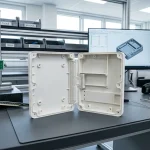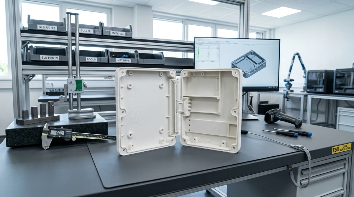
Designing moving mechanical joints often introduces assembly bottlenecks and fastener costs. Specifically, engineers creating custom enclosures or moving linkages can eliminate separate hardware by using 3D printed hinges.
Modern additive manufacturing builds fully functional joints in one setup. For example, shops can create thin living hinges, interlocking pin hinges, and spherical ball joints without secondary screws.
Consequently, aerospace, electronics, and robotics teams accelerate prototype verification cycles. Furthermore, consolidation lowers assembly part counts and trims overall production expenses.
In addition, at AS Prototypes, our additive floor provides industrial custom 3D printing services alongside climate-controlled metrology labs. In this guide, we review key hinge geometries, recommended print clearances, and proven engineering design rules.
Core Architectural Types of 3D Printed Hinges
Specifically, engineers choose between three fundamental hinge architectures based on torque, cycle count, and space constraints.
First, living hinges rely on a thin, flexible plastic web connecting two rigid walls. As a result, they fold smoothly through continuous material deflection rather than surface sliding.
Second, assembled pin hinges use distinct knuckles connected by a steel dowel pin or press-fit rod. In addition, this design offers high torsional rigidity and handles substantial shear forces.
Third, print-in-place mechanisms build interlocking hinge knuckles and internal pins simultaneously. Therefore, the joint functions immediately right after clearing excess un-sintered powder or support resin.
| Hinge Architecture | Minimum Clearance | Recommended AM Process | Ideal Material | Cycle Fatigue Life |
|---|---|---|---|---|
| Living Hinge Web | N/A (Web thickness 0.4 – 0.8 mm) | SLS / MJF Powder Bed | Nylon PA12 / Polypropylene | Over 100,000 flex cycles |
| Print-in-Place Pin Hinge | 0.30 mm to 0.50 mm radial gap | SLS / High-Res SLA | Nylon PA11 / Tough Resin | Medium (Low-friction wear) |
| Assembled Dowel Hinge | 0.10 mm to 0.20 mm bore fit | SLA / Precision SLS | PA12-GF / Aluminum 6061 | Heavy-duty industrial rating |
| Spherical Ball Joint | 0.35 mm spherical clearance | SLS / MJF | Nylon PA12 | Multi-axis positioning joints |
Clearance Tolerances and Critical DFM Rules
In practice, successful print-in-place hinges depend on precise radial clearances between moving knuckles.
For example, if clearances are too narrow, adjacent surfaces fuse during melting or photopolymer curing. In contrast, excessive clearance creates sloppy joint wobble and uneven mechanical wear.
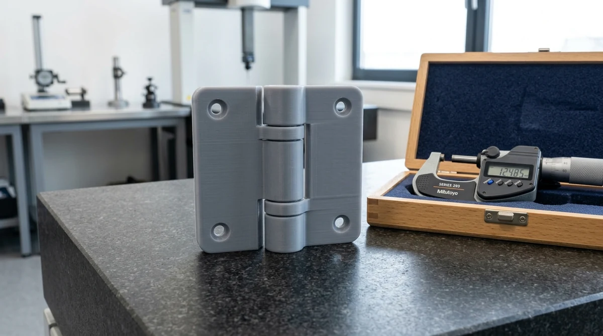
Next, for powder bed systems like SLS 3D printing, maintain a minimum gap of 0.40 mm. Consequently, this clearance allows un-sintered polymer powder to evacuate cleanly during bead blasting.
In addition, orientation during slicing directly dictates knuckle roundness. Therefore, always align the hinge pin axis parallel to the print bed plane to minimize stair-stepping artifacts.
| Polymer Material | Tensile Elongation | Flexural Fatigue Limit | Hinge Suitability | Key Engineering Note |
|---|---|---|---|---|
| Nylon PA12 (SLS / MJF) | 15% to 20% | Superior resistance | Outstanding for living hinges | Anneal immediately after unpacking. |
| Polypropylene (PP) | Over 100% | Near-infinite flex life | Industry benchmark standard | Resists chemical solvents and moisture. |
| Tough Engineering Resin | 35% to 45% | Moderate flex endurance | Best for fine pin hinges | Provides ultra-smooth cosmetic finish. |
| PETG Filament (FDM) | 20% to 25% | Low to moderate | Good for early concept mockups | Layer lines create weak notch planes. |
Post-Processing and Mechanical Validation
Overall, proper post-processing ensures smooth articulation and extends fatigue life.
Specifically, immediately after printing, Automated metrology setup teams flex living hinges repeatedly while warm. As a result, this initial mechanical training aligns polymer crystalline chains along the hinge axis.
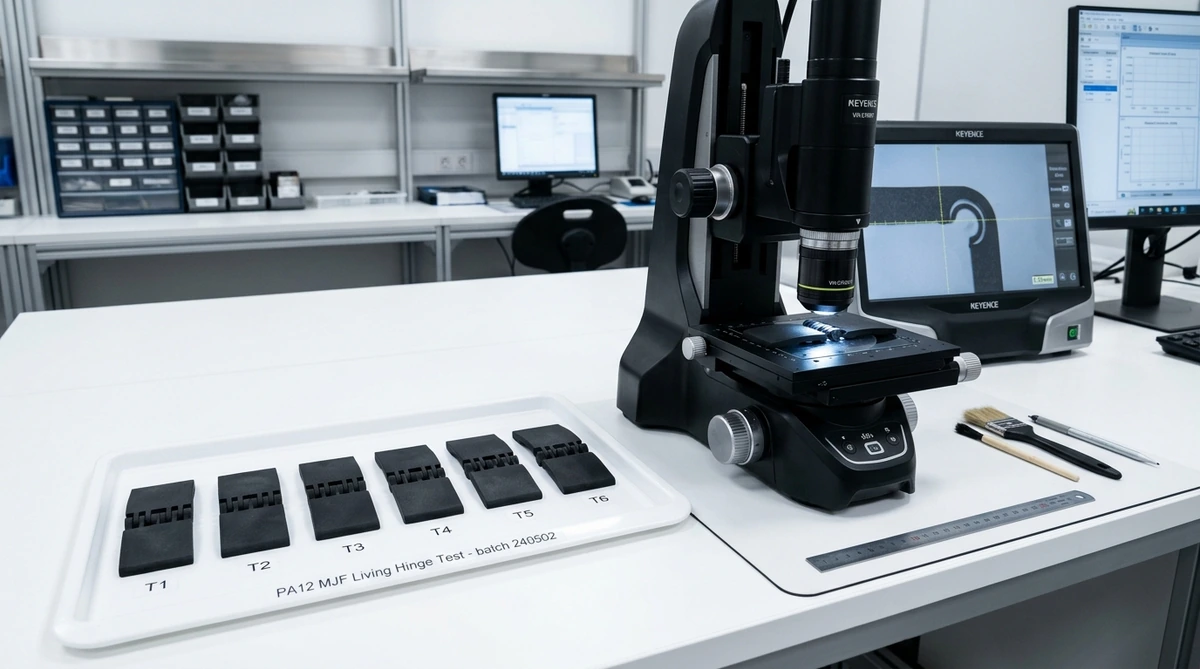
In addition, optical measurement systems inspect inner knuckle radii to ensure zero burrs. Furthermore, lubricating assembled knuckles with PTFE spray reduces friction during repetitive cycles.
For SLS and MJF nylon PA12, keep living hinge web thickness between 0.40 mm and 0.60 mm. In addition, maintain generous transition fillets of at least 1.0 mm radius to prevent stress concentration.
Specifically, maintain a radial clearance of 0.35 mm to 0.50 mm for SLS powder beds. In comparison, for high-resolution SLA resin printers, clearances can be reduced down to 0.20 mm to 0.30 mm.
Orienting the hinge pin parallel to print layers prevents shear forces from pulling layer bonds apart. Consequently, this orientation delivers maximum tensile endurance and smooth knuckle rotation.
Need Functional 3D Printed Hinges and Prototypes?
AS Prototypes provides industrial SLS, MJF, and SLA additive manufacturing with tight mechanical tolerances. Upload your CAD drawings today for expert DFM advice and instant pricing.
Upload CAD Models for Instant Quote