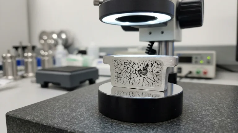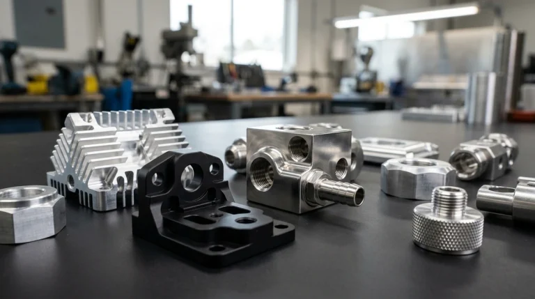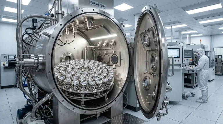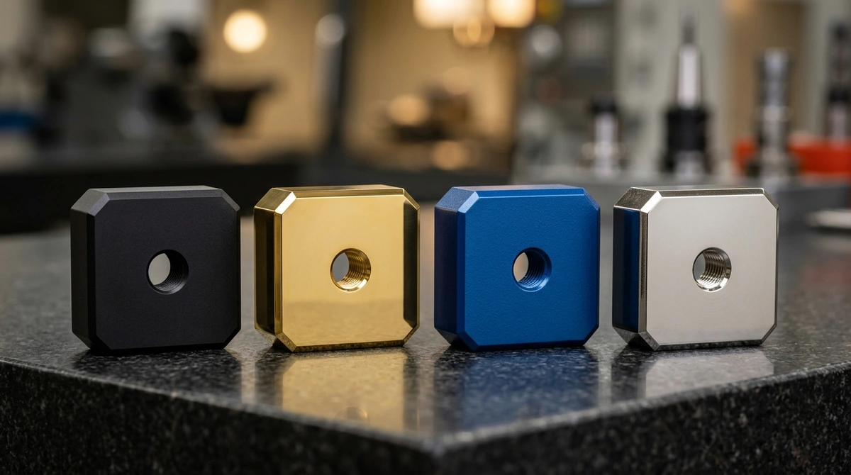
Aluminum alloys dominate modern mechanical engineering due to their exceptional strength-to-weight ratios, high thermal conductivity, and superior machinability. However, raw aluminum exhibits a natural surface vulnerability: atmospheric oxidation forms a fragile, porous oxide film only 2 to 5 nanometers thick. In aggressive operating environments—such as marine salt spray, automotive engine bays, or industrial chemical exposures—unprotected aluminum readily suffers from pitting, galvanic corrosion, and mechanical surface degradation.
Specifying the optimal surface coating is a critical engineering decision that balances dimensional tolerance budgeting, wear resistance, electrical insulation, dielectric breakdown, thermal emissivity, and cosmetic appeal. The three premier industrial coating paradigms for aluminum components are Electrochemical Anodizing, Electrostatic Powder Coating, and Polyurethane/Epoxy Liquid Painting. This engineering guide examines their underlying chemical and physical mechanics, structural film attributes, dimensional allowances, and Design for Manufacturing (DFM) masking protocols to empower engineers to make data-driven material selections.
1. Electrochemical Anodizing: Conversion Chemistry & Film Growth
Unlike additive surface coatings that deposit an external polymer layer onto the substrate, anodizing is an electrolytic conversion process. The aluminum component functions as the anode within an acid electrolyte bath (predominantly 15–20% sulfuric acid, H2SO4). When direct current (DC) is applied between the aluminum workpiece and lead or stainless steel cathodes, water molecules disassociate, driving nascent oxygen ions to react with the substrate:
2Al + 3O2- → Al2O3 + 6e–
This reaction forms an ordered, hexagonal cellular matrix of aluminum oxide (γ-Al2O3) with microscopic central pores that can be dyed in vibrant colors before hot deionized water or nickel acetate hydration sealing.
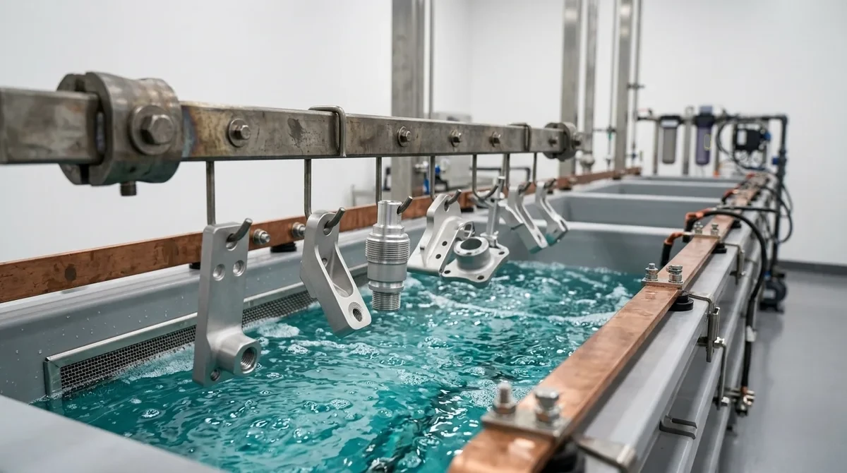
The 50/50 Growth and Penetration Dynamic
The defining metallurgical characteristic of sulfuric anodizing is its dimensional split: approximately 50% of the oxide layer penetrates inward into the base aluminum substrate, while 50% builds outward beyond the original machined boundary. Engineering specifications must account for this behavior:
- MIL-A-8625 Type II (Commercial / Sulfuric Anodize): Produces a total coating thickness of 10 to 25 μm (0.4 to 1.0 mil). External dimensional growth per surface is approximately 5 to 12.5 μm (0.005 to 0.0125 mm), increasing a critical shaft diameter by 10 to 25 μm.
- MIL-A-8625 Type III (Hardcoat Anodize): Formulated at near-freezing bath temperatures (0°C to 4°C) and elevated current densities (up to 3.5 A/dm2), producing a dense coating of 45 to 60 μm (1.8 to 2.4 mil). Surface growth is approximately 23 to 30 μm per face.
Engineering Advantages of Anodizing
- Exceptional Microhardness and Wear Resistance: Hardcoat anodizing achieves exceptional surface microhardness ratings of 400 to 550 HV0.05 (per ASTM B578 / ISO 10074), approaching sapphire hardness. Macro Rockwell HRC testing is never used on thin anodic films due to the “eggshell effect” where the 150 kgf indenter crushes through the 50 μm ceramic film into the ductile aluminum substrate. Under Taber abrasion testing (CS-17 wheel, 1,000 g load), hardcoat anodize outperforms hard chrome plating.
- Superior Thermal Emissivity: Natural mill-finish aluminum exhibits an emissivity (ε) of only 0.04 to 0.06, acting as a thermal radiation reflector. Black anodizing elevates emissivity to ε = 0.85–0.92, dramatically boosting radiative heat dissipation in convection-limited electronic heatsinks and avionics chassis.
- Dielectric Insulation: Anodized alumina is an electrical insulator with dielectric breakdown voltages exceeding 1,000 V to 2,500 V DC, preventing galvanic bridge faults in multi-metal assemblies.
- Zero Peeling or Flaking: Because the anodic film is an integral metallurgical extension of the parent crystal lattice, delamination, blister formation, or peeling is physically impossible.
2. Electrostatic Powder Coating: Thermoset Polymer Fusion
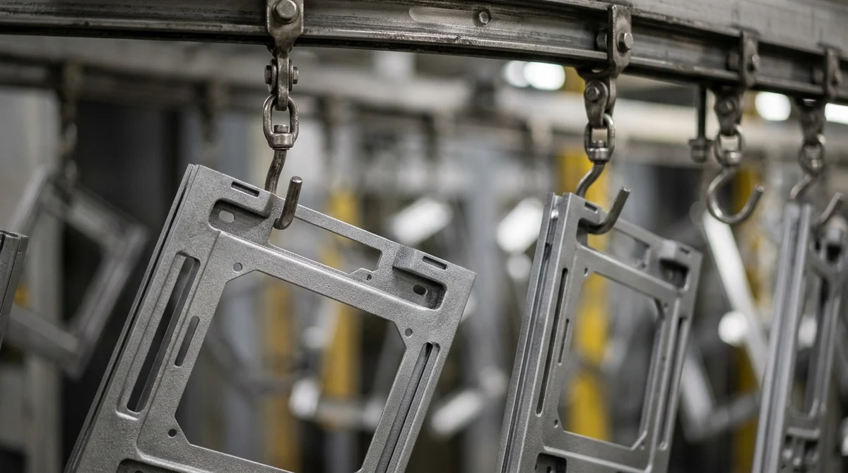
Electrostatic powder coating is an additive polymer finishing process that replaces solvent-borne carriers with dry, micronized polymer resin particles (typically 30 to 50 μm particle size). Suspended parts on an automated overhead conveyor enter an environmentally controlled spray booth, where electrostatic corona spray guns impart a negative electrostatic charge (-30 to -90 kV) to the pulverized powder. The grounded aluminum part attracts the charged cloud with high wrap-around transfer efficiency.
Once coated, the components are transferred to a thermal convection curing oven at 180°C to 200°C (356°F to 392°F) for 15 to 25 minutes. Under thermal excitation, the polymer granules melt, cross-link, and coalesce into an unbroken, high-density polymer film.
Resin Chemistries and Film Properties
Powder coating formulations are tailored to specific mechanical and atmospheric demands:
- Polyester (TGIC and TGIC-Free): The dominant exterior standard (Qualicoat Class 1 and Class 2). Offers outstanding UV stability, gloss retention, and resistance to chalking under prolonged solar exposure.
- Epoxy Powders: Delivers benchmark mechanical impact toughness, chemical immersion resistance, and salt spray protection, though susceptible to UV chalking, making it ideal for internal enclosures and structural frames.
- Polyurethane & Hybrid Blends: Balances chemical resistance, flexibility, and smooth orange-peel-free architectural aesthetics.
Key Engineering Trade-offs
- High Film Build (60 to 120 μm): Powder coating creates a robust external barrier layer (2.4 to 4.7 mil). This thick layer excels at masking extrusion weld lines, light CNC tool marks, and casting porosity, but it will aggressively choke internal threads (M2 to M8) and tight dowel bores unless masked with precision silicone plugs.
- Extreme Impact and Flexural Toughness: Because the cross-linked polymer retains molecular elasticity, powder-coated aluminum can endure direct impact energy exceeding 160 in-lb (ASTM D2794) and 180-degree mandrel bending without cracking or chipping.
- Corrosion Barrier Superiority: High-grade polyester powder over a multi-stage zirconium or silane conversion pretreatment reliably exceeds 1,500 to 3,000 hours of continuous neutral salt spray exposure (ASTM B117).
- Thermal Insulation Penalty: With low thermal conductivity (κ < 0.25 W/m·K), thick powder coatings act as a thermal blanket, making them unsuitable for direct-conduction heat dissipation pads.
3. Liquid Painting: High-Precision Wet Films & Complex Geometries
Liquid wet spray painting involves atomizing a liquid paint system—comprising pigments, binders, and volatile organic solvents—using high-volume low-pressure (HVLP) pneumatic guns or electrostatic centrifugal bells. For precision engineering applications, industrial coaters utilize two-component (2K) reactive liquid polyurethane topcoats over high-solids epoxy or chromate-free etch primers.
When Liquid Paint Outperforms Powder and Anodize
- Low Curing Temperature Envelope: While powder coating requires a 180°C–200°C bake that can anneal cold-worked tempers (such as 7075-T6 or 6061-T6 sheet metal) or melt elastomeric sub-gaskets, liquid polyurethane cures at ambient room temperature (20°C–25°C) or mild force-dry temperatures (60°C–80°C).
- Controlled Thin Film Thickness (25 to 50 μm): Liquid paint can be applied in fine, controllable dry film thicknesses (DFT) ranging from 25 to 40 μm, minimizing thread interference and keeping precision clearances intact.
- Unlimited Color and Visual Finishes: Liquid paint provides unparalleled cosmetic flexibility, supporting exact Pantone/RAL/automotive metallic flake matching, pearlescent effects, soft-touch tactile coatings, and gloss levels ranging from dead matte (5 GU) to piano gloss (95+ GU).
- Assembly Repair and Field Touch-Up: Minor scratches on liquid painted parts can be spot-repaired, wet-sanded, and polished on-site without stripping the entire assembly.
4. Comprehensive Engineering Comparison: Aluminum Surface Coatings
The following engineering matrix evaluates the physical, dimensional, and environmental properties of the primary aluminum coating processes:
| Performance Attribute | Type II Anodize | Type III Hardcoat Anodize | Electrostatic Powder Coat | 2K Polyurethane Liquid Paint |
|---|---|---|---|---|
| Process Classification | Electrochemical Conversion | Electrochemical Conversion | Electrostatic Thermoset Polymer | Pneumatic Atomized Solvent Polymer |
| Total Film Thickness | 10 – 25 μm (0.4 – 1.0 mil) | 45 – 65 μm (1.8 – 2.6 mil) | 60 – 120 μm (2.4 – 4.7 mil) | 25 – 50 μm (1.0 – 2.0 mil) |
| Dimensional Build per Face | +5 to +12.5 μm (50% growth) | +22.5 to +32.5 μm (50% growth) | +60 to +120 μm (100% additive) | +25 to +50 μm (100% additive) |
| Surface Hardness | 250 – 350 HV0.05 (Microhardness) | 400 – 550 HV0.05 (Microhardness per ASTM B578) | Pencil Hardness 2H – 4H | Pencil Hardness F – 2H |
| Abrasion / Wear Resistance | Moderate | Extremely High (Taber < 15 mg loss) | High (Resilient Elasticity) | Moderate to Good |
| Salt Spray (ASTM B117) | 336 – 500 Hours | 1,000+ Hours (Sealed) | 1,500 – 3,000+ Hours | 500 – 1,000 Hours |
| Thermal Emissivity (ε) | 0.80 – 0.88 (Black) | 0.85 – 0.92 (High Radiative) | 0.70 – 0.75 (Thermal Barrier) | 0.75 – 0.80 |
| Electrical Insulation | Breakdown > 500 V | Breakdown > 1,500 – 2,500 V | High Dielectric (> 5 kV) | Moderate to High Dielectric |
| Cure / Processing Temp | 18°C – 22°C (Bath) | 0°C – 4°C (Chilled Bath) | 180°C – 200°C (Oven Bake) | 20°C (Air) or 60°C – 80°C (Low Bake) |
| Typical Application Focus | Consumer electronics, optical frames | Aerospace hydraulics, sliding gears, heatsinks | Outdoor frames, robotics chassis, automotive | Medical bezels, luxury interior trim, prototypes |
5. Design for Manufacturing (DFM): Tolerancing, Masking & Pretreatment
1. Pre-Machining Tolerance Budgeting
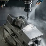
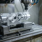
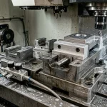
Precision CNC parts cannot be machined to nominal final dimensions if thick coatings are applied. At AS Prototypes, our manufacturing engineering team incorporates coating allowances directly into CAM toolpaths:
- Internal Threads: For powder-coated parts, internal threads from M2 to M8 will bind if coated. They must be masked using high-temperature silicone tapered pull plugs. Alternatively, for thin anodizing (Type II), thread taps can be selected with higher pitch-diameter limits (e.g., GH3 vs GH2) to ensure free-running fasteners after conversion.
- Bearing Bores and Dowel Fits: Precision H7 bearing bores must be plugged or post-machined. Type III hardcoat on an H7 bore will reduce the inside diameter by 45 to 60 μm, destroying the intended transition or interference fit.
2. Critical Masking Techniques
Selective coating allows engineers to achieve multi-functional part zones:
- Silicone Masking Plugs and Caps: Rated for up to 315°C (600°F), reusable silicone hardware seals blind holes, through holes, and male stud threads during powder coating and chemical immersion.
- Polyimide (Kapton) Adhesive Films: Precision die-cut Kapton tape masks grounding pads and EMI/RFI shielding contact faces, leaving bare conductive aluminum substrate intact.
- CNC Machined Fixturing Masking: For high-volume production, custom titanium or fluoropolymer masking pucks clamp over delicate sealing surfaces, preventing chemical ingress in anodizing baths.
3. Surface Pretreatment and Chemical Conversion
Coating adhesion failure (blistering or delamination) stems almost universally from improper substrate preparation. A comprehensive industrial pretreatment sequence includes:
- Alkaline Degreasing: Removes heavy CNC coolants, oils, and synthetic drawing lubricants at 50°C–65°C.
- Acid Deoxidation / Desmutting: Dissolves insoluble intermetallic alloying smut (copper, silicon, iron) that accumulates on 2024, 6061, and 7075 alloys.
- Non-Chromate Chemical Conversion (Zr/Ti Pretreatment): In powder coating and painting lines, applying a nanotechnology zirconium or titanium conversion film (MIL-DTL-5541 Class 3 equivalent) delivers an optimal chemical anchor, boosting cross-hatch tape adhesion to ASTM D3359 5B.
6. Material-Specific Coating Considerations
The metallurgical composition of the aluminum alloy significantly dictates coating quality and cosmetic uniformity:
- 6000-Series Alloys (6061, 6063, 6082): The premier candidates for both clear and colored anodizing, powder coating, and liquid painting. Minimal intermetallic alloying impurities ensure clear, uniform, and streak-free anodic oxide growth.
- 7000-Series Alloys (7075, 7050): High zinc content yields a bronze or amber hue during hard anodizing. Because zinc precipitates can degrade coating continuity, strict bath current ramping and chilled temperatures are mandatory.
- 2000-Series Alloys (2024, 2011): Elevated copper content (> 4%) limits anodic film thickness and decreases corrosion resistance. Special electrolyte additives and lowered voltages are required.
- Die-Cast Alloys (A380, ADC12): High silicon content (> 9%) renders decorative anodizing impractical due to dark gray/black smutting. Die castings are preferentially finished with electrostatic powder coating or liquid painting after shot blasting to seal surface micro-porosity.
Partner with AS Prototypes for Precision Machining & Turnkey Finishing
Navigating the intricate balance between tight machining tolerances and post-finish coating buildup requires rigorous engineering expertise. AS Prototypes delivers end-to-end prototyping and low-volume manufacturing under one roof—from multi-axis CNC milling and Swiss turning to precision Type II/III hard anodizing, electrostatic powder coating, and high-spec liquid finishing.
Every batch undergoes rigorous quality assurance, including eddy-current coating thickness verification (ASTM B244), cross-hatch adhesion testing (ASTM D3359), and CMM coordinate dimensional inspection.
Type III hardcoat anodic films are only 45 to 60 µm thick. Under the standard 150 kgf Rockwell C test load, the diamond indenter instantly punches through the brittle ceramic layer into the soft aluminum base (eggshell effect). Hardness must be measured using a micro-Vickers diamond pyramid indenter under 25 to 50 gf loads (HV0.025 or HV0.05).
Anodized films are electrically non-conductive with dielectric breakdown voltages exceeding 1,000V. Grounding pads and EMI shielding surfaces must be selectively masked and treated with chemical conversion coating (Alodine 1200S or SurTec 650 per MIL-DTL-5541 Class 3) to maintain contact resistance below 5 milliohms.
Type III hardcoat anodizing penetrates into the substrate by 50% and builds outward by 50%. On 60° internal thread flanks, the outward surface buildup (t_build ≈ 0.5 × T) shrinks the effective pitch diameter by four times the outward growth, which equals two times the total coating thickness (ΔD2 = 4 × t_build = 2 × T_total). Machinists must tap internal threads using oversized taps (6GX or 6HX) or program pre-plate CAM pitch offsets prior to anodizing.