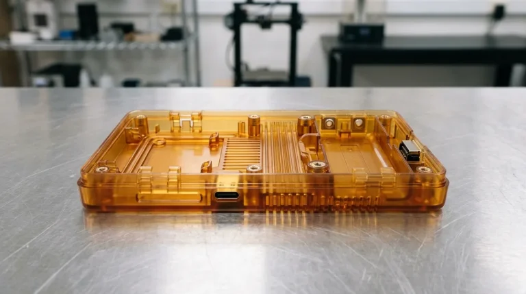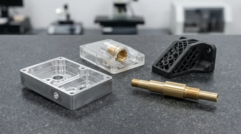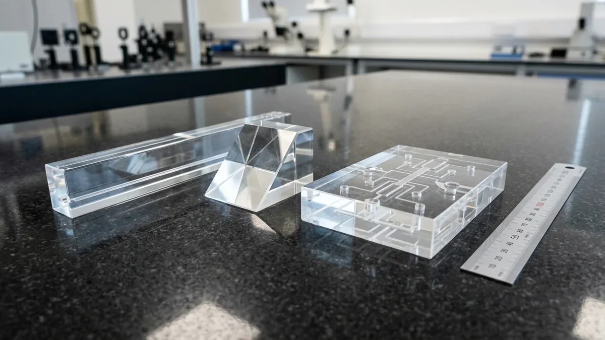
PolyMethyl MethAcrylate (PMMA), widely recognized as optical acrylic or plexiglass, represents the premier transparent thermoplastic for high-precision optical prototypes, medical microfluidic chips, sensor windows, and automotive light guides. Boasting an exceptional luminous transmittance of 92.5%—surpassing standard float glass (~90%) and optical polycarbonate (~89%)—PMMA delivers unrivaled clarity, high Abbe number dispersion stability, and absolute resistance to UV-induced yellowing.
However, transforming an as-machined, translucent PMMA block into an optically flawless, glass-like component is one of the most demanding challenges in polymer manufacturing. Poor machining parameters induce friction melting and surface smearing; aggressive clamping creates residual internal tension; and improper polishing causes edge roll-off or micro-crazing.
This engineering guide details the four foundational rules and advanced shop-floor methodologies required to achieve SPI A-1 optical clarity in precision CNC machining PMMA prototypes.
Quick Engineering Summary: 4 Core Rules for Clear PMMA Prototypes
- Rule 1: Mandate Cell-Cast Acrylic: Never use extruded acrylic for precision optical milling. Cell-cast PMMA provides higher molecular weight, superior thermal resistance, zero extrusion stresses, and clean chip formation.
- Rule 2: Polished Single O-Flute Tooling & Vortex Air: Cut dry using polished single-flute carbide end mills with 15°–20° rake angles and high-velocity vortex cold-air guns (-5°C). Never use flood liquid coolants that trigger environmental stress cracking.
- Rule 3: Multi-Stage Diamond Hand Buffing: Replace aggressive flame or vapor polishing with sequential deionized wet sanding (800 to 5000 grit) and sub-micron diamond paste buffing (1.0 µm to 0.25 µm) to achieve true SPI A-1 optical flatness (Ra < 0.012 µm).
- Rule 4: Controlled Thermal Annealing: Eliminate residual machining stresses by baking parts at 80°C–85°C (1 hour per 5mm thickness) followed by slow furnace cooling (≤ 10°C/hr) to permanently eliminate solvent crazing.
Table of Contents: PMMA Prototyping Engineering Guide
- Rule 1: Material Selection – Cell-Cast PMMA vs. Extruded Acrylic & Optical Polymers
- Rule 2: CNC Tool Geometry, Cutting Dynamics & Thermal Friction Mitigation
- Rule 3: Progressive Micro-Abrasive Sanding & Optical Diamond Buffing
- Rule 4: Thermal Stress Relief Annealing to Eliminate Crazing Networks
- Optical GD&T Verification, Profilometry & CMM Metrology Standards
- Shop-Floor Failure Modes: Root Causes & Engineering Countermeasures
- Frequently Asked Questions (FAQ)
- Request an Instant RFQ & Optical DFM Review
Rule 1: Material Selection – Cell-Cast PMMA vs. Extruded Acrylic & Optical Polymers
Selecting raw polymer stock is the single most critical engineering decision in optical prototyping. Machining catastrophic failures—such as gummy chip re-welding, cloudy internal hazing, and delayed stress crazing—almost universally originate from specifying continuous extruded acrylic sheet instead of high-grade cell-cast PMMA. Understanding the polymer physics behind these two manufacturing methods explains why cell-cast acrylic is irreplaceable for high-precision optical components.
Cell-Cast PMMA (Cast Acrylic) is produced by casting liquid methyl methacrylate monomer between two polished float-glass plates, followed by a slow, highly controlled batch polymerization cycle. This process yields an extremely high average molecular weight (MW > 1,000,000 g/mol) characterized by long, intertwined polymer chains. The resulting material exhibits superior Rockwell hardness (M95 to M100), higher heat deflection temperatures (HDT of 95°C to 105°C), and zero directional extrusion tension.
During CNC milling, cell-cast PMMA shears cleanly into crisp, discrete ribbon chips without softening. Most importantly, its cross-linked molecular density enables mechanical polishing down to sub-micron optical mirror finishes (SPI A-1) with virtually zero optical distortion.
Continuous Extruded Acrylic, by contrast, is manufactured by forcing melted PMMA pellets through a profile die using a continuous screw extruder. This rapid processing method limits the polymer molecular weight to approximately 100,000 to 200,000 g/mol and freezes substantial directional orientation stresses into the sheet. Extruded PMMA has a lower softening threshold (HDT of 80°C to 88°C). When subjected to the shear heat of an end mill, extruded acrylic softens prematurely, gummy plastic wraps around the cutter flutes, and deep residual stresses react catastrophically with cleaning solvents or ambient humidity, creating thousands of microscopic craze lines.
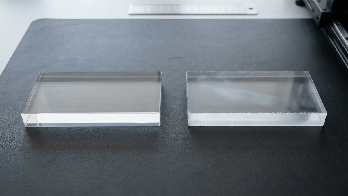
Snell’s Law and Optical Physics dictate how light travels through precision PMMA components. With a refractive index of n = 1.491 at the sodium D-line (589.3 nm), the critical angle (θc) for Total Internal Reflection (TIR) at an acrylic-air boundary is calculated using Snell’s Law:
θc = arcsin(nair / nPMMA) = arcsin(1.000 / 1.491) ≈ 42.16°
Optical dispersion and Abbe number further differentiate PMMA from other transparent thermoplastics. PMMA features an Abbe number of Vd ≈ 58, indicating exceptionally low chromatic dispersion compared to optical polycarbonate (Vd ≈ 30). In precision prisms, lens arrays, and automotive light pipes, PMMA maintains color purity across the entire visible spectrum (400 nm to 700 nm), preventing chromatic aberration fringing that plagues polycarbonate optics.
Transparent optical polymer matrix compares the fundamental physical, optical, and mechanical properties of PMMA against alternative clear engineering thermoplastics used in modern prototyping:
| Polymer Material | Luminous Transmittance | Refractive Index (nD) | Abbe Number (Vd) | HDT (°C @ 0.45 MPa) | Surface Hardness | Machinability & Finish |
|---|---|---|---|---|---|---|
| Cell-Cast PMMA (Acrylic) | 92.5% | 1.491 | 58 (Very Low Dispersion) | 95°C – 105°C | Rockwell M95 | Excellent; Buffs to SPI A-1 Mirror |
| Extruded PMMA (Acrylic) | 91.0% | 1.490 | 57 | 80°C – 88°C | Rockwell M85 | Poor; Prone to Gummy Melting |
| Optical Polycarbonate (PC) | 89.0% | 1.586 | 30 (High Dispersion) | 135°C – 142°C | Rockwell M70 | Ductile; Vapor Polishes Easily |
| Cyclic Olefin Copolymer (COC) | 91.8% | 1.533 | 56 | 130°C – 170°C | Rockwell M88 | Good; Bio-Inert Microfluidics |
| Optical Liquid Silicone (LSR) | 94.0% | 1.410 | 50 | > 200°C | Shore A 70 | Molded Only; Non-Machinable |
Rule 2: CNC Tool Geometry, Cutting Dynamics & Thermal Friction Mitigation
Thermal dynamics in acrylic machining differ fundamentally from metal cutting. PMMA is an excellent thermal insulator with a thermal conductivity of merely 0.19 W/(m·K)—nearly 900 times lower than 6061 aluminum (~167 W/(m·K)). Because heat cannot dissipate through the workpiece, virtually 100% of the frictional energy generated during chip formation remains concentrated at the cutting edge and in the evacuated chip.
If tool geometry or feeds and speeds allow cutting zone temperatures to exceed the glass transition point (Tg ≈ 105°C), the acrylic instantly softens, gums up the flute, and re-welds behind the tool, leaving gouged, frosted white tracks.
Cutter geometry specifications are essential to achieve razor-clean shearing rather than plowing or rubbing:
- Single-Flute Up-Cut Spiral End Mills (O-Flute): Multi-flute tools (2 or 4 flutes) trap acrylic chips within narrow flute valleys. High-performance optical milling mandates mirror-polished, single-flute solid carbide O-flute end mills. The massive single-flute pocket allows continuous, curled chips to eject upward immediately without re-cutting or friction rubbing.
- High Positive Rake Angle (15° to 20°): A sharp, positive rake angle slices through the ductile polymer chain with minimal cutting force, generating low residual shear stress in the subsurface.
- Generous Primary Relief Clearance (12° to 15°): High clearance angles prevent the tool flank from rubbing against the freshly machined acrylic wall as the material undergoes elastic recovery.
- Sub-Micron Polished Flute Surface (Ra < 0.05 µm): Flute valleys must be optically polished or DLC (Diamond-Like Carbon) coated to eliminate microscopic surface friction that causes molten chip adhesion.
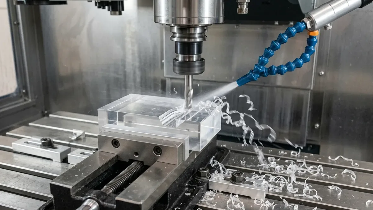
Cold-air vortex cooling versus chemical coolants is an absolute shop-floor rule. Flood liquid coolants—particularly petroleum-based cutting oils, synthetic emulsions, and chlorinated fluids—must never contact PMMA. Acrylic is highly vulnerable to Environmental Stress Cracking (ESC). Solvents and surfactants attack microscopic polymer voids, triggering immediate or delayed crazing networks across the entire component. AS Prototypes operates high-velocity compressed air vortex tubes delivering dry, filtered sub-zero cold air (-5°C to 0°C) directly at the cutting zone. The cold air stream solidifies the ribbon chip instantly and propels it out of the machining envelope.
Feeds, speeds, and chip load equations govern precision acrylic milling. Spindle speed (n, RPM) and table feed rate (vf, mm/min) must be coordinated to maintain a consistent chip load per tooth (fz):
fz = vf / (n × z) | Target fz: 0.06 mm – 0.12 mm/tooth (Roughing) | 0.02 mm – 0.04 mm/tooth (Finishing)
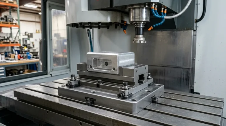
Shop-floor machining reality: High-speed 3-axis and 4-axis Vertical Machining Centers (VMCs) equipped with high-RPM ceramic bearing spindles (18,000 to 24,000 RPM) handle over 80% of precision acrylic prototyping. Parts are secured using smooth aluminum soft jaws, precision machinist vises with copper protective liners, or custom vacuum chucks. Simultaneous 5-axis machining is reserved specifically for complex automotive light-pipe freeform contours and curved microfluidic manifolds.
| Machining Operation | Tool Type & Diameter | Spindle Speed (RPM) | Feed Rate (mm/min) | Axial DOC (ap) | Radial Stepover (ae) | Cooling & Evacuation |
|---|---|---|---|---|---|---|
| Rough Contouring | D6mm 1-Flute Carbide O-Flute | 14,000 – 16,000 | 1,200 – 1,800 | 2.0 – 3.5 mm | 40% Tool Diameter | Vortex Cold Air (-5°C) |
| Semi-Finishing | D4mm 1-Flute Polished Carbide | 16,000 – 18,000 | 800 – 1,200 | 0.8 – 1.2 mm | 20% Tool Diameter | Vortex Cold Air (-5°C) |
| Optical Fine Finishing | D3mm Single PCD Diamond Tool | 18,000 – 22,000 | 400 – 600 | 0.15 – 0.25 mm | 8% – 12% Stepover | High-Flow Clean Dry Air |
| Micro-Channel Milling | D0.5mm – D1.0mm Micro End Mill | 24,000 – 30,000 | 150 – 250 | 0.05 – 0.10 mm | 50% Tool Diameter | Continuous Micro-Nozzle Air |
Rule 3: Progressive Micro-Abrasive Sanding & Optical Diamond Buffing
Understanding surface topography off the CNC milling machine explains why as-machined acrylic appears frosted or cloudy. Even with single-crystal diamond cutters, sequential stepover passes leave micro-scallops (Rz ≈ 0.8 µm to 1.6 µm). These microscopic cusps diffuse and scatter incident light randomly, dropping specular transmission to under 40%. Restoring the native 92.5% optical transparency requires disciplined, multi-stage abrasive finishing to systematically flatten surface irregularities down to less than one-tenth of the wavelength of visible light (Ra < 0.05 µm).
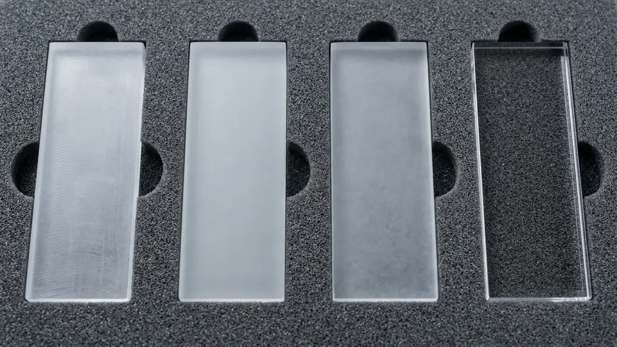
Four-stage optical finishing progression transforms rough tool marks into an optical mirror plane:
- Stage 1: Deionized Wet Sanding (800 to 1200 Grit): Technicians perform sequential wet sanding in alternating 90° cross-hatch strokes using silicon carbide waterproof papers. Deionized water acts as a dedicated flushing medium to float abrasive debris away and prevent localized frictional heat. This stage levels all primary milling cusps, establishing a uniform satin matte baseline (Ra ≈ 0.4 µm).
- Stage 2: Micro-Abrasive Lapping (2000 to 3000 Grit): Ultra-fine abrasive micro-papers refine the scratch pattern. Technicians maintain light, even pressure against flat granite lapping plates to ensure edge geometries and optical datum planes remain true without corner roll-off (Ra ≈ 0.15 µm).
- Stage 3: Ultra-Fine Finishing (5000 Grit): A final wet-lapping pass with 5000-grit micro-abrasives eliminates all directional scratch tracks, leaving a translucent, haze-free surface that begins transmitting specular light (Ra ≈ 0.05 µm).
- Stage 4: Diamond Paste Mechanical Buffing (SPI A-1 Standard): Final optical clarity is achieved using high-density felt bob wheels running at low speeds (1,200 to 1,800 RPM) charged with sub-micron diamond polishing compound (1.0 µm down to 0.25 µm), followed by a cerium oxide optical slurry. The compound mechanically shears residual micro-asperities without melting the polymer matrix, producing a flawless SPI A-1 optical mirror finish (Ra < 0.012 µm).
Why flame and vapor polishing fail on precision PMMA: While flame polishing (hydrogen-oxygen torch) and solvent vapor polishing are common in sign fabrication or polycarbonate finishing, they are fundamentally destructive to precision optical prototypes. Flame polishing liquefies the top 0.1mm surface layer, inducing severe localized thermal stress, edge rounding, and orange-peel optical distortion. Furthermore, flame-polished PMMA components craze immediately upon contact with assembly cleaners or moisture. Solvent vapor polishing (such as dichloromethane) attacks acrylic indiscriminately, causing milky hazing and micro-porosity. Mechanical diamond buffing remains the only process capable of delivering both geometric precision and 92.5% optical clarity.
| Finishing Stage | Abrasive Media / Media Size | Lubricant / Medium | Target Roughness (Ra) | Visual Optical State |
|---|---|---|---|---|
| As-Machined (CNC) | Carbide O-Flute / PCD | Dry Cold Air Stream | 0.8 – 1.6 µm | Translucent / Frosted Cusps |
| Coarse Wet Sanding | 800 – 1200 Grit SiC Paper | Deionized Water | 0.3 – 0.5 µm | Uniform Satin Matte |
| Fine Wet Sanding | 2000 – 3000 Grit SiC Paper | Deionized Water | 0.10 – 0.15 µm | Semi-Transparent / Low Haze |
| Micro-Lapping | 5000 Grit Micro-Abrasive | Deionized Water | 0.04 – 0.06 µm | Near-Specular Transmission |
| Optical Diamond Buffing | 0.25 µm Diamond + Cerium Slurry | Low-Speed Felt Wheel | < 0.012 µm (SPI A-1) | 100% Crystal-Clear Optical Glass |
Rule 4: Thermal Stress Relief Annealing to Eliminate Crazing Networks
Residual internal tension is the invisible killer of machined acrylic components. Even when cutting parameters and vortex air cooling are perfectly executed, mechanical clamping pressures, cutting shear forces, and surface buffing friction induce localized tensile stresses beneath the surface layer (frequently measuring 15 to 25 MPa). If an unannealed PMMA prototype is subsequently exposed to isopropyl alcohol (IPA), bonding solvents, or even ambient thermal cycling, these locked-in tensile stresses release violently via microscopic failure networks known as crazing.
Polymer crazing mechanics involve localized polymer chain uncoiling under tensile stress, forming microscopic micro-voids interconnected by thin polymer fibrils. Solvents act as plasticizers, lowering the energy required for craze propagation. Within hours, crazing degrades structural integrity, turns optical light guides completely milky, and creates leak paths across microfluidic channel gaskets.
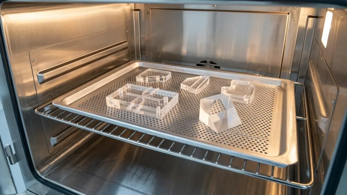
Mandatory thermal annealing protocol subjects all finished acrylic prototypes to a strict convection oven heat treatment schedule before inspection and delivery:
- Flat Part Placement: Components must be placed 100% flat on perforated aluminum baking trays inside a forced-convection oven. Parts must never be stacked, tilted, or subjected to gravitational bending moments during heating.
- Controlled Ramp-Up Rate (≤ 15°C/hr): The oven temperature is raised gradually from room temperature at a controlled rate not exceeding 15°C per hour to reach the soak temperature of 80°C to 85°C (safely 15°C below the PMMA heat deflection point). Rapid heating induces differential thermal expansion that warps thin-walled sections.
- Thermal Soak Duration: The peak temperature is maintained for 1 hour per 5mm of maximum cross-sectional thickness, with a minimum soak time of 2 hours. This provides sufficient thermal energy for frozen polymer chains to relax and relieve internal stresses.
- Controlled Furnace Cooling (≤ 10°C/hr): The cooling rate must be strictly controlled at 10°C per hour or slower until the chamber drops below 40°C before opening the oven door. Removing parts at elevated temperatures introduces fresh thermal gradient shocks, completely undoing the stress relief cycle.
| Wall / Section Thickness | Ramp-Up Rate | Soak Temperature | Soak Time (Minimum) | Ramp-Down Cooling Rate | Unload Temperature |
|---|---|---|---|---|---|
| Up to 5 mm (0.20 in) | 15°C / hour | 80°C – 82°C | 2.0 Hours | 10°C / hour | < 40°C |
| 6 mm to 12 mm (0.24 – 0.47 in) | 12°C / hour | 82°C – 85°C | 3.0 – 4.0 Hours | 8°C / hour | < 38°C |
| 13 mm to 25 mm (0.51 – 1.00 in) | 10°C / hour | 83°C – 85°C | 5.0 – 6.0 Hours | 6°C / hour | < 35°C |
| > 25 mm (Thick Optics / Manifolds) | 8°C / hour | 82°C – 84°C | 8.0 – 12.0 Hours | 5°C / hour | < 32°C |
Optical GD&T Verification, Profilometry & CMM Metrology Standards
Metrology verification of transparent acrylic requires specialized techniques because optical clarity frustrates standard optical scanners. Laser line triangulation scanners and structured light cameras experience internal beam refraction and specular scattering on polished PMMA, returning noisy point clouds. Applying temporary matte anti-glare sprays is unacceptable for precision optics, as spray residues contaminate micro-fluidic channels and micro-scratches occur during post-inspection wipe down.
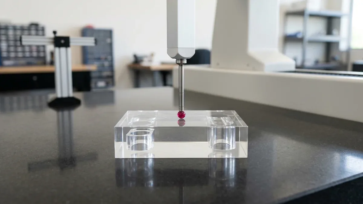
Zeiss Coordinate Measuring Machine (CMM) touch-trigger metrology delivers verified GD&T compliance for optical acrylic prototypes. Metrology engineers mount ultra-low contact force probes fitted with spherical ruby styli (R = 1.0 mm or 2.0 mm). Probing trigger forces are calibrated below 0.05 N to ensure the ruby ball touch-probes the acrylic Datum A reference plane without leaving microscopic indentations. Machined PMMA prototypes rest directly on pure granite surface plates without heavy mechanical clamps, guaranteeing free-state verification under drawing-specified tolerances (±0.02 mm / ±0.0008 in).
Optical spectrophotometry and profilometry validate functional performance. Surface finish is verified using non-contact optical white-light interferometry, confirming surface roughness below Ra < 0.012 µm. Luminous transmission and haze are measured in accordance with ASTM D1003 across the 380 nm to 780 nm spectrum, certifying minimum 92.5% transmission and < 0.5% optical haze prior to shipment.
Shop-Floor Failure Modes: Root Causes & Engineering Countermeasures
Troubleshooting acrylic prototype defects requires quick diagnosis of cutting mechanics, thermal dynamics, and chemical interactions. The following matrix outlines the most frequent shop-floor failures and their proven remedies:
| Defect / Failure Mode | Visual Appearance | Primary Root Cause | Shop-Floor Engineering Countermeasure |
|---|---|---|---|
| Melted Chip Re-Welding | Opaque, white smeared lumps fused onto milled surface | Multi-flute tool pack; cutting temp > 105°C; dull cutter | Switch to single O-flute carbide tool; apply vortex cold-air (-5°C); increase feed per tooth to evacuate heat in chip. |
| Thread Tapping Crazing | Micro-cracks radiating outwards from tapped holes | Standard cutting tap wedges polymer; stress crazing | Use single-point thread milling; oversize tap drill diameter by 0.1mm; or install ultrasonic brass threaded inserts. |
| Solvent-Induced Crazing | Spider-web cracks appearing minutes after cleaning | Cleaning with IPA, ethanol, or acetone on unannealed part | Mandate 80°C–85°C thermal annealing cycle; clean PMMA only with mild soap solution, deionized water, or specialized acrylic cleaners. |
| Optical Edge Rolloff | Distorted reflections along outer boundaries of prisms | Excessive buffing wheel pressure or soft cloth wrap | Lap on rigid granite plate with hard felt pads; maintain flat planar contact; restrict felt wheel dwell time at sharp edges. |
| Microchannel Gasket Leakage | Fluid seepage across bonded microfluidic chip layers | Part warpage from machining stress or uneven torque | Anneal components prior to bonding; design tongue-and-groove sealing beads; verify Datum A flatness ≤ 0.015 mm. |
Frequently Asked Questions (FAQ)
Cell-cast PMMA is synthesized via slow batch polymerization between precision glass plates, resulting in an ultra-high molecular weight (> 1,000,000 g/mol) and superior surface hardness (Rockwell M95). It chips cleanly without melting during CNC milling, does not clog end mills, and polishes to a crystal-clear SPI A-1 mirror finish with zero optical haze or directional extrusion stress.
Precision acrylic milling mandates polished, single-flute solid carbide up-cut spiral end mills (O-flute) with a high positive rake angle (15° to 20°) and generous primary clearance (12° to 15°). The massive single-flute valley ejects ribbon chips immediately before heat can transfer into the workpiece, preventing chip re-welding and white edge gouging.
Petroleum-based and water-soluble emulsion coolants contain hydrocarbons, surfactants, and chemical additives that trigger Environmental Stress Cracking (ESC) in acrylic under cutting tension. AS Prototypes utilizes high-velocity vortex cold-air guns delivering filtered dry air at -5°C, dissipating frictional heat while maintaining complete chemical neutrality.
Machining and clamping introduce localized subsurface tensile stresses (15 to 25 MPa). Convection oven annealing at 80°C–85°C (1 hour per 5mm of section thickness) provides the thermal activation energy needed for frozen polymer chains to relax. Slow furnace cooling (≤ 10°C/hr) prevents thermal shock, eliminating crazing when components contact cleaning fluids or assembly solvents.
Flame polishing melts the outer 0.1mm surface layer, causing severe edge rounding, orange-peel optical distortion, and extreme residual surface tension that crazes immediately upon chemical exposure. Sequential micro-abrasive wet sanding (800 to 5000 grit) followed by diamond paste buffing (1.0 µm to 0.25 µm) removes material mechanically, preserving flat optical datum planes, sharp chamfers, and achieving true SPI A-1 clarity.
Partner with AS Prototypes for Optical-Clear PMMA Prototypes
Request an Instant RFQ for Precision Optical Acrylic Machining
Whether you require automotive light pipe prototypes, crystal-clear medical microfluidic chips, optical prism arrays, or show-grade exhibition enclosures, AS Prototypes delivers diamond-machined optical craftsmanship. Our in-house CNC machining facility combines high-RPM vertical machining centers, vortex cold-air technology, multi-stage diamond buffing, and coordinate Zeiss CMM inspection to achieve guaranteed SPI A-1 optical clarity.