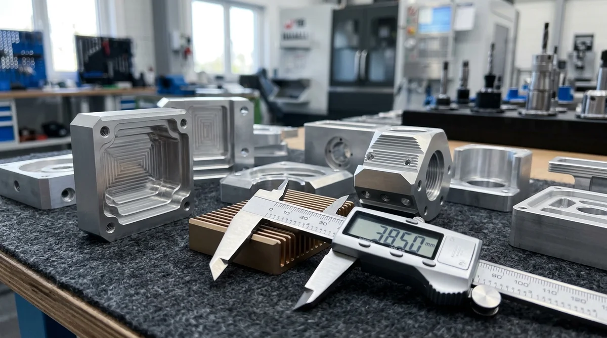
Aluminum rapid prototyping is the definitive benchmark for validating high-performance mechanical designs, thermal management systems, and structural enclosures before committing to volume tooling. Renowned for its exceptional strength-to-weight ratio, superior thermal conductivity, and predictable machinability, aluminum bridges the critical gap between conceptual digital models and production-grade physical assemblies. In our precision CNC machining and rapid prototyping facility, deploying the right aluminum grade, toolpath strategy, and stress-relieving protocol ensures prototypes deliver identical mechanical integrity to final production components.
1. High-Performance Aluminum Alloys for Rapid Prototyping
Selecting the optimal alloy requires balancing yield strength, fatigue endurance, thermal expansion, and post-machining surface treatment response. The vast majority of precision prototypes utilize wrought aerospace and structural grade alloys:
- 6061-T6 (General-Purpose Structural & Optical Assemblies): The primary workhorse for prototype engineering. Offering a yield strength of 276 MPa, outstanding corrosion resistance, and superb weldability, 6061-T6 machines cleanly and serves as the industry standard for decorative and protective anodizing.
- 7075-T651 (Aerospace & High-Stress Mechanisms): Zinc-alloyed grade delivering tensile strengths exceeding 570 MPa—comparable to structural carbon steels at one-third the density. The stress-relieved T651 temper minimizes distortion during heavy stock removal, making it mandatory for robotics armatures, high-pressure manifolds, and structural load frames.
- 5083-H111 (Marine & Extreme Chemical Environments): A non-heat-treatable magnesium-manganese alloy renowned for exceptional resistance to saltwater corrosion and cryogenic stability. Ideal for subsea sensor housings and chemical instrumentation.
- 2024-T3 / T351 (High-Fatigue Dynamic Tooling): Copper-alloyed grade with high fracture toughness and cyclic fatigue resistance. While more vulnerable to atmospheric corrosion, it excels in cyclic tension-compression prototype testing.
| Alloy Grade | Yield Strength (MPa) | Machinability Rating | Thermal Conductivity (W/m·K) | Anodizing Response | Primary Prototype Applications |
|---|---|---|---|---|---|
| 6061-T6 | 276 | Excellent (80%) | 167 | Superior (Clear & Color) | Sensor housings, brackets, electronics enclosures |
| 7075-T651 | 503 | Good (70%) | 130 | Moderate (Type III Hardcoat) | Robotics arms, high-load linkages, aerospace brackets |
| 5083-H111 | 145 | Moderate (60%) | 121 | Good (Corrosion-resistant) | Marine enclosures, cryogenic vessels, chemical fixtures |
| 2024-T351 | 325 | Good (75%) | 121 | Fair (Requires sealing) | Aircraft structural fittings, cyclic fatigue test rigs |
2. DFM Rules & CNC Tooling Dynamics for Aluminum Prototypes
Modern rapid prototyping leverages high-speed 3-axis and 5-axis CNC machining to mill intricate geometries directly from solid billet. However, adhering to stringent Design for Manufacturability (DFM) rules prevents tool chatter, excessive deflection, and premature cutter failure:
- Internal Corner Radii: Internal vertical corners should always maintain a radius R ≥ 1/3 D of the cavity depth. Pocket depths of 30 mm should specify at least an R5 mm or R6 mm corner radius, allowing rigid endmills to operate without corner deceleration and chatter marks.
- Wall Thickness Limitations: While aluminum boasts excellent stiffness, thin vertical walls deflect under cutting pressure. Maintain minimum wall thicknesses of 0.8 mm for unsupported walls under 25 mm in height, and 1.5 mm for taller structural ribs.
- Deep Pocket Aspect Ratios: Keep pocket depths under 4× the tool diameter. Pockets exceeding 5:1 aspect ratios require extended-reach tooling, reduced feed rates, and high-pressure through-spindle coolant to evacuate chips cleanly.
- Flute Geometry & Chip Evacuation: In our machine shop, we deploy 2-flute and 3-flute polished solid carbide endmills with 45° helix angles and DLC (Diamond-Like Carbon) coatings. This prevents aluminum chip welding (built-up edge) and allows surface cutting speeds upwards of 600 m/min.
3. Workholding, Residual Stress Management & Distortion Control
One of the greatest challenges in aluminum rapid prototyping is managing internal residual stresses, particularly when pocketing asymmetric geometries. As large volumes of material are removed from rolled plate or extruded bar, unbalanced internal stresses cause the workpiece to bow, twist, or cup.
To ensure tight geometric tolerance compliance, our engineering protocol implements a multi-stage stress mitigation workflow:
- Pre-Stretched Billets: We strictly specify stress-relieved tempers (such as T651 or T7351), which undergo mechanical stretching following quenching to neutralize internal stress fields.
- Two-Stage Roughing & Finishing: Heavy roughing clears 85% to 90% of excess stock, leaving 0.5 mm uniform stock on all critical surfaces. The part is subsequently unclamped to permit natural elastic stress relaxation before final finish passes.
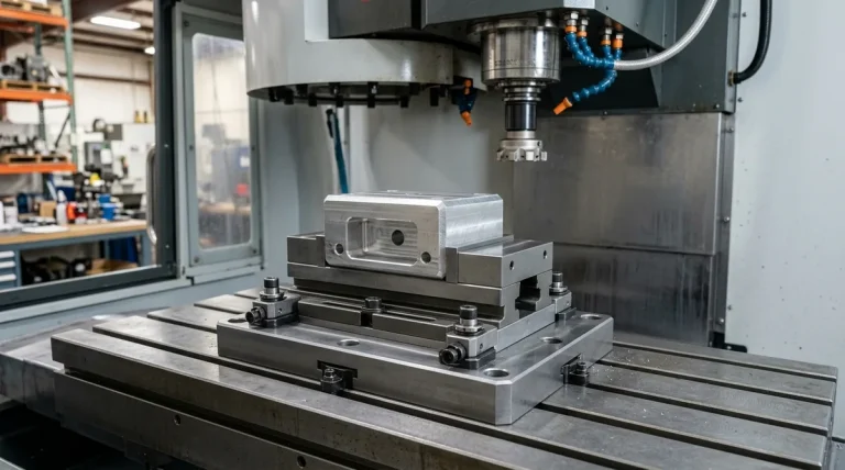
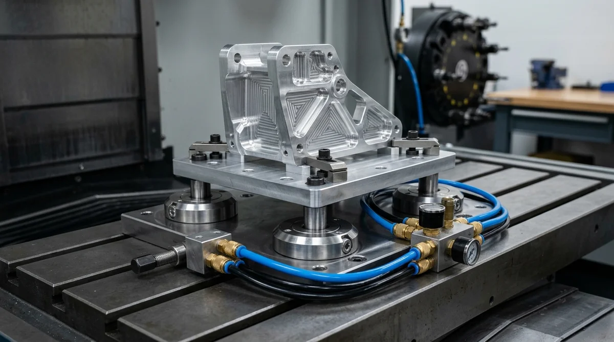
- Low-Stress Clamping & Vacuum Fixtures: For thin-walled enclosures and optical baseplates, traditional high-pressure vises induce compressive distortion. We utilize custom soft aluminum pie jaws, multi-point low-profile toe clamps, or porous ceramic vacuum chucks to distribute hold-down forces evenly.
4. Precision Tolerances, Thermal Drift & Quality Inspection
Aluminum exhibits a relatively high coefficient of thermal expansion (α ≈ 23 × 10⁻⁶ / K). In unconditioned environments, a 5°C ambient temperature swing produces over 0.023 mm of dimensional drift across a 200 mm aluminum span, exceeding precision machining allowances.
| Feature Type | Standard Tolerance | Precision Tolerance | Metrology & Verification Tooling |
|---|---|---|---|
| Linear Dimensions (≤ 100 mm) | ±0.050 mm | ±0.010 mm | Mitutoyo digital micrometers / Height gage |
| H7 Bore Diameters | +0.015 / -0.000 mm | +0.008 / -0.000 mm | Three-point bore micrometers / Air gages |
| Flatness & True Position | 0.050 mm / 100 mm | 0.012 mm / 100 mm | Bridge-type Zeiss CMM / Renishaw tactile probes |
| Surface Roughness (Ra) | Ra 1.6 µm (As-milled) | Ra 0.4 µm (Diamond faced) | Stylus profilometer / Optical confocal metrology |
Our machining centers operate in climate-controlled environments stabilized at 20°C ± 1°C. Machined prototypes are soaked on granite inspection plates before undergoing multi-axis probe routines and CMM verification, ensuring complete conformity to GD&T callouts.
5. Precision Surface Finishing & Environmental Protection
While bare aluminum naturally forms a thin passivation oxide layer, engineering prototypes frequently require specialized surface finishes to enhance wear resistance, electrical insulation, optical absorption, or aesthetic appeal:
- Bead Blasting (Media Blasting): Utilizing #100 to #150 fine glass beads or aluminum oxide at controlled air pressures (0.3 to 0.4 MPa) to eradicate subtle cutter paths and produce a uniform, non-directional satin matte texture.
- Type II Anodizing (Sulfuric Acid Bath): Produces a controlled oxide layer between 10 µm and 25 µm thick. Can be dyed clear, black, blue, gold, or custom cosmetic shades while providing excellent atmospheric corrosion protection.
- Type III Hardcoat Anodizing: Processed at near-freezing temperatures (0°C to 5°C) to generate a dense, microcrystalline oxide layer 40 µm to 60 µm deep with a microhardness rating of 450 to 550 HV0.05. Ideal for sliding sleeves, guide tracks, and aerospace wear surfaces.
- Chemical Conversion Coating (Chromate / Chem Film): Provides electrical conductivity while protecting against corrosion, serving as an outstanding primer for subsequent electrostatic powder coating.
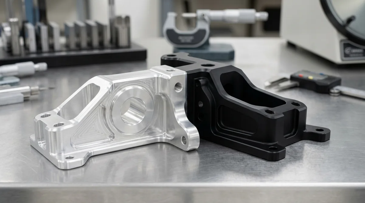
Alloy 6061-T6 is the premier choice for prototypes requiring cosmetic or protective anodizing. Its metallurgical composition produces a clean, vibrant, and uniform anodic film. Conversely, 7075-T6 contains higher zinc and copper concentrations, resulting in an olive or bronze tint when clear anodized, making it better suited for dark-dyed or hardcoat applications.
We mitigate warping through a three-tier approach: sourcing pre-stretched T651 billets, executing balanced multi-stage roughing with 0.5 mm rest allowances followed by unclamping for stress relief, and utilizing vacuum chucks or low-stress custom soft jaws to avoid mechanical pinching during final finishing passes.
For critical bearing bores, dowel pin locations, and ground mating faces, our 3-axis, 4-axis and 5-axis CNC machining centers routinely achieve tolerances of ±0.010 mm to ±0.020 mm. Standard linear features are held to ISO 2768-mK general tolerances or drawing-specified precision tolerances under constant 20°C temperature-controlled conditions.
Accelerate Your Aluminum Rapid Prototyping Projects
Whether you require single functional concept prototypes, complex aerospace brackets, or pilot production runs with custom anodized finishes, our in-house engineering and CNC manufacturing facility delivers micron-accurate components within rapid prototype turnarounds from 4 to 8 business days.
Upload your STEP, IGES, or 2D drawing files directly to our engineering team for a comprehensive DFM review and instant manufacturing quotation: