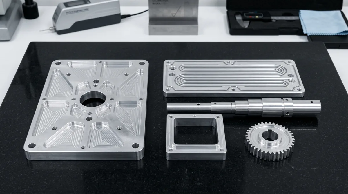
Aluminum prototype fabrication serves as the premier manufacturing pathway for engineering teams developing high-performance hardware across aerospace, automotive, robotics, and consumer electronics industries. Combining one-third the density of carbon steel with exceptional yield strength, superior thermal dissipation, and unparalleled machinability, aluminum alloys bridge the critical transition between conceptual 3D CAD modeling and pilot series production. In our precision CNC machining facility, deploying multi-axis machining centers, tight metrology inspection, and full-spectrum surface finishing guarantees aluminum prototypes satisfy exacting functional, environmental, and aesthetic demands.
- Core Focus & DFM Scope: Actionable shop-floor engineering guidelines for aluminum prototype fabrication, covering material selection, geometric tolerancing, and defect prevention.
- Achievable Tolerance Envelope: General features hold ISO 2768-mK; critical bearing bores, dowel pins, and mating datums hold ±0.010 to ±0.020 mm (±0.0004″ to ±0.0008″), with Wire EDM/grinding to ±0.005 mm (±0.0002″).
- Machining & Surface Integrity: High-speed 3-axis and 4-axis VMCs (with simultaneous 5-axis for complex contours) delivering as-machined Ra 0.8 µm (32 µin) to Ra 0.4 µm (16 µin) per ASME B46.1.
- Metrology & Process Control: On-machine spindle probing paired with 20°C (68°F) climate-controlled Zeiss CMM coordinate verification and calibrated Go/No-Go plug/ring gauges.
- Ex-Factory Turnaround: 4 to 8 business days for as-machined rapid prototypes; 7 to 12 business days for anodized, plated, or multi-operation production runs (excluding 3–5 days air transit).
1. Exceptional Strength-to-Weight Ratio for Lightweighting
Modern engineering design is dominated by the lightweighting imperative. With a nominal density of only 2.7 g/cm³ (compared to 7.85 g/cm³ for carbon steel), aluminum enables drastic structural mass reduction without sacrificing structural rigidity or dynamic performance:
- Aerospace-Grade Performance: Utilizing high-strength aluminum 7075-T6 yields yield strengths exceeding 503 MPa and ultimate tensile strengths above 570 MPa, surpassing typical mild carbon steels (such as A36) while slashing component rotational inertia in high-speed robotics and UAV gimbal mechanisms.
- Payload and Energy Optimization: In electric vehicles (EVs) and battery energy storage systems, lightweight aluminum structural frames and cooling trays extend driving range and reduce suspension unsprung mass.
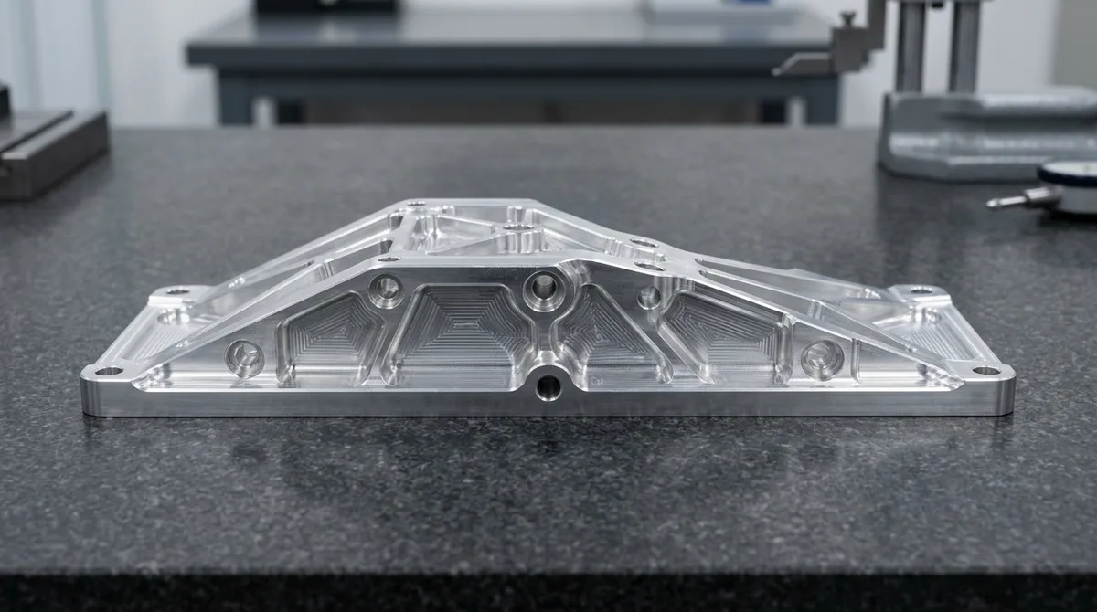
2. Rapid Subtractive Machinability and Low Tooling Wear
The non-ferrous, ductile metallurgy of aluminum allows CNC machine tools to operate at extraordinary surface cutting speeds (SFM > 2500):
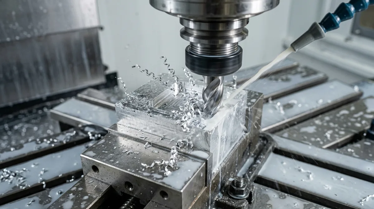
- Accelerated Spindle Feeds: Modern vertical machining centers run spindle speeds between 15,000 and 24,000 RPM, cutting material 3 to 5 times faster than titanium or stainless steel alloys.
- Reduced Cycle Times and Cost: High material removal rates (MRR) translate directly into shorter spindle hours, lowering prototype production costs and delivering functional metal parts in 4 to 8 business days (Ex-Factory).
| Engineering Property | Aluminum 6061-T6 | Aluminum 7075-T6 | 304 Stainless Steel | POM-C (Engineering Acetal) |
|---|---|---|---|---|
| Density (g/cm³) | 2.70 | 2.81 | 8.00 | 1.41 |
| Yield Strength (MPa) | 276 | 503 | 215 | 68 |
| Thermal Conductivity (W/m·K) | 167 | 130 | 16.2 | 0.31 |
| Machinability Index | 85% (Fast, crisp) | 75% (Crisp chip break) | 45% (Work-hardening) | 100% (Very Fast) |
| Relative CNC Machining Cost | Low (Baseline) | Low – Moderate | High (Slow feeds) | Low |
3. Superior Thermal and Electrical Conductivity
Aluminum is the premier material choice for thermal dissipation hardware and electrical busbar packaging:
- High-Efficiency Heat Sinks: With thermal conductivity reaching 167 W/(m·K) (over 10 times higher than stainless steel), aluminum rapidly draws concentrated heat away from microprocessors, high-power LED arrays, and EV battery modules.
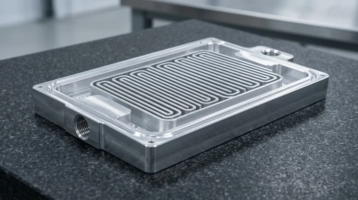
- Integrated Fluid Cooling Channels: Machining serpentine fluid channels directly into aluminum liquid cold plates allows prototypes to endure rigorous thermal dynamometer testing without thermal throttling.
4. Non-Magnetic & RF Electromagnetic Shielding
In sensitive electronics and medical diagnostic instruments, magnetic interference can disrupt performance:
- Aluminum is completely non-magnetic, making it the standard casing material for MRI peripheral hardware and laboratory spectrometry tools.
- Acting as a continuous conductive Faraday cage, CNC machined aluminum chassis attenuate radio frequency interference (RFI) and electromagnetic interference (EMI), ensuring prototypes pass regulatory FCC/CE compliance.
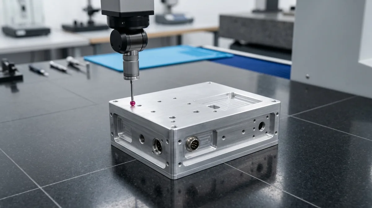
5. Tight Geometric Tolerances & Dimensional Stability
When stress-relieved billets (such as 6061-T651 or 7075-T7351) are machined on calibrated 3-, 4-, and 5-axis machining centers, aluminum maintains extraordinary dimensional fidelity:
- Critical bearing bores and dowel pin holes consistently achieve ISO 286-2 H7 tolerances (within ±0.008 mm).
- Planar mounting datum faces regularly hold flatness below 0.015 mm, ensuring leak-tight O-ring sealing under hydraulic and pneumatic pressures.
6. Excellent Ductility and Weldability
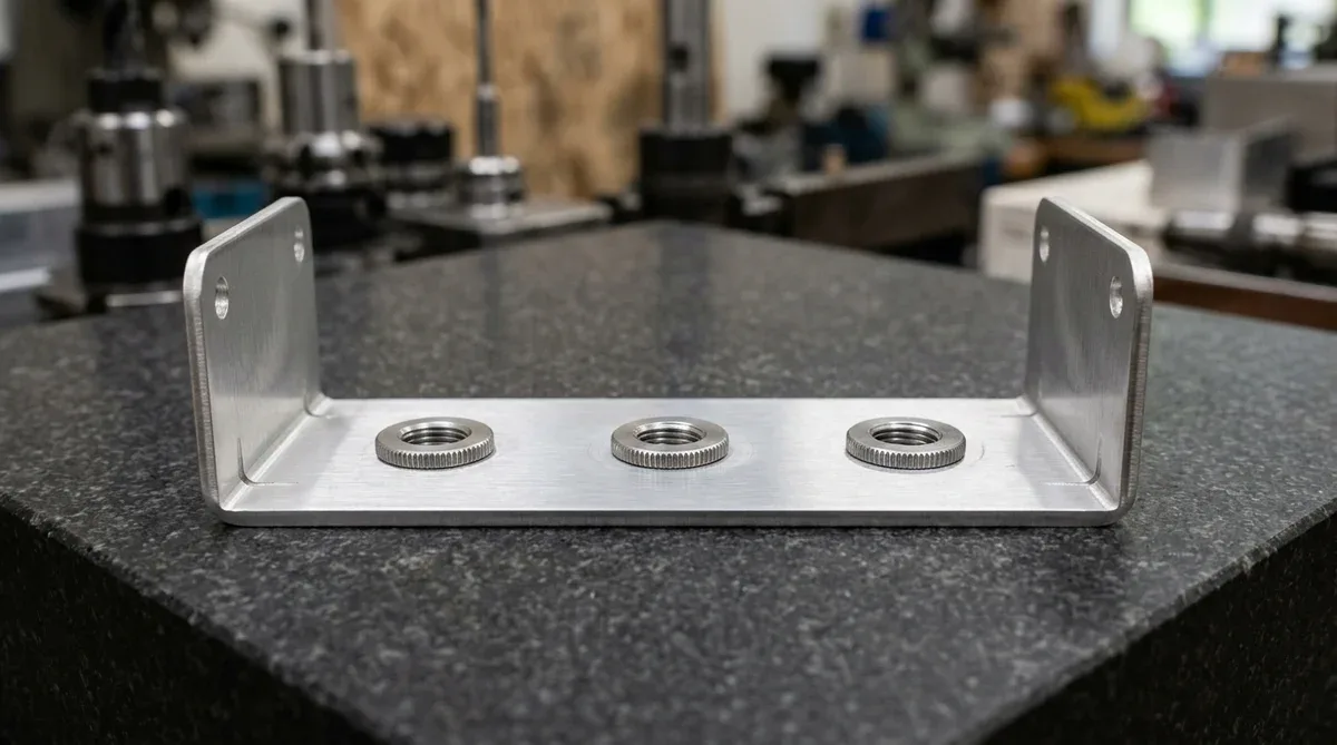
Unlike brittle cast irons or ultra-hard ceramics, structural aluminum alloys such as 6061-T6 and 5083-H111 exhibit remarkable ductility:
- Prototypes can be cold-formed, tapped, or bent into complex sheet metal brackets without micro-cracking.
- Readily weldable using TIG (GTAW) and MIG (GMAW) welding processes, enabling hybrid assemblies that combine thick CNC machined billet bosses with welded sheet metal enclosures.
7. Full-Spectrum Surface Finishing and Anodizing
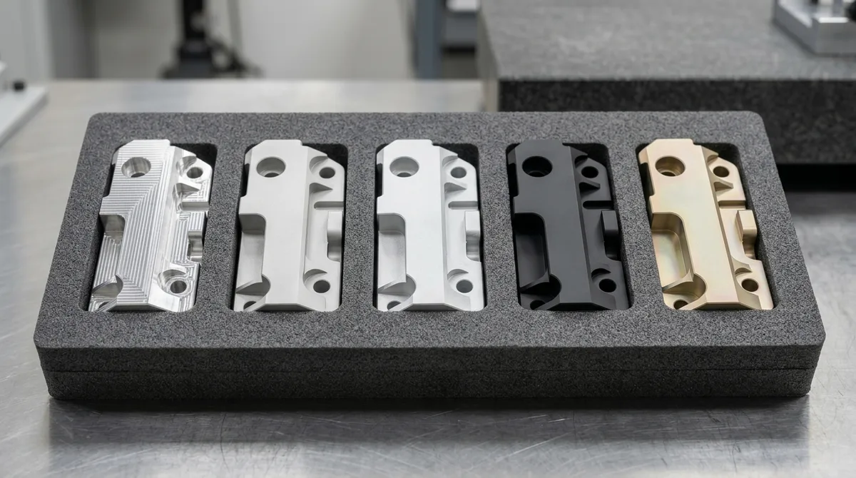
Aluminum accepts an extensive range of chemical, mechanical, and electrochemical surface finishing treatments:
| Surface Finish Type | Process Specification | Surface Texture / Appearance | Primary Engineering Benefit |
|---|---|---|---|
| As-Machined Standard | Direct off CNC milling table | Ra 0.8 – 1.6 μm with visible toolpaths | Fastest turnaround; lowest unit cost |
| Bead Blasting | #120 – #150 fine glass beads | Uniform satin matte texture | Eliminates directional tool marks; pre-anodize prep |
| Type II Color Anodizing | MIL-A-8625 Type II (10–25 μm) | Vibrant dyes (Black, Clear, Blue, Red) | Cosmetic appeal; moderate corrosion protection |
| Type III Hardcoat Anodize | MIL-A-8625 Type III (25–50 μm) | Dark grey / bronze ceramic layer | Extreme surface hardness (> 500 HV0.05 microhardness); wear resistance |
| Chemical Film (Alodine) | MIL-DTL-5541 Class 1A/3 | Iridescent gold or clear passivation | Electrically conductive corrosion protection |
8. Natural Corrosion Resistance via Self-Passivation
Upon exposure to atmospheric oxygen, aluminum instantly forms a microscopic, impervious aluminum oxide (Al2O3) film (2 to 4 nanometers thick). This natural barrier halts general atmospheric oxidation and environmental moisture corrosion, ensuring components maintain surface integrity during extended testing cycles (note: dielectric isolation is required when mating with stainless steel or carbon fiber in electrolytic environments to prevent galvanic corrosion).
9. Infinite Recyclability and Sustainable Manufacturing
Aluminum is one of the most environmentally sustainable engineering materials in industrial production. Swarf chips generated during CNC milling are 100% collected and remelted, consuming 95% less energy than primary bauxite smelting. This circular lifecycle lowers production footprints for environmentally conscious hardware brands.
Why Do Aluminum Prototype Fabrication Components Fail Tight Tolerances in Production, and How Do You Prevent It?
Maintaining repeatable accuracy in aluminum prototype fabrication requires controlling radial tool deflection, internal residual stress relaxation, and thermal expansion drift across multi-axis setups. While general unmated features reliably conform to ISO 2768-mK, holding critical mating bores and datum surfaces within ±0.010 mm (±0.0004″) demands staged roughing-to-finishing stress relief and rigid workholding.
Shop-Floor Quantitative Derivation: Cantilever Tool Deflection & Thermal Drift Compensation
In our Shenzhen CNC machine shop, preventing wall taper and bore bell-mouthing in aluminum prototype fabrication begins with calculating cantilever end-mill deflection (δ) before releasing G-code to the spindle. Modeled as a cylindrical carbide beam of diameter D and stickout length L subjected to radial cutting force Fr, tool deflection follows the fourth-power stiffness law:
δ = (64 × Fr × L³) / (3 × π × E × D⁴)
For a solid carbide end mill (E = 600 GPa / 87,000 ksi) with diameter D = 8.0 mm (0.315″), stickout L = 36 mm (4.5×D), and radial cutting load Fr = 180 N (40.5 lbf), the resulting deflection is δ = (64 × 180 × 36³) / (3 × 3.1416 × 600,000 × 4,096) = 0.0232 mm (0.00091″)—instantly consuming a ±0.010 mm (±0.0004″) drawing tolerance! By stepping up to a D = 10.0 mm (0.394″) corner-radius tool and reducing stickout to L = 28 mm (2.8×D) with a 0.15 mm (0.006″) semi-finishing spring pass (Fr = 45 N), radial deflection drops to δ = 0.0011 mm (0.00004″), locking true position and cylindricity well within print limits.
Step-by-Step Shop-Floor Execution & Quality Protocol
To bridge CAD intent with repeatable shop-floor delivery, our engineering team enforces a four-stage execution workflow across every prototype and low-volume production batch:
- Step 1: Datum Hierarchy & 3/4/5-Axis Workholding Design: Align primary, secondary, and tertiary GD&T datums (A-B-C) with precision Kurt vises, custom-contoured 6061 aluminum soft jaws, or zero-point pneumatic pallets to minimize re-clamping datum shift.
- Step 2: Roughing & Intermediate Stress-Relief Stabilization: Execute high-efficiency trochoidal roughing leaving 0.30 to 0.50 mm (0.012″ to 0.020″) uniform stock, followed by unclamping or thermal stress-relief stabilization to release rolled-billet internal tension.
- Step 3: On-Machine Probing & Climate-Controlled Finishing: Re-probe work coordinate offsets via infrared spindle touch probes in a 20°C (68°F) shop environment, then execute climb-milling finish passes to achieve Ra 0.4–0.8 μm (16–32 μin).
- Step 4: Zeiss CMM Verification & Surface Treatment Masking: Perform first-article and batch inspection on programmable Zeiss CMM systems, applying silicone plugs to H7 bores and tapped threads prior to MIL-A-8625 anodizing or ASTM A967 passivation.
Shop-Floor Defect Troubleshooting & Corrective Action Matrix
When evaluating part geometry during pre-production DFM review, our manufacturing engineers screen for the following failure modes and apply proven corrective controls:
| Defect / Symptom | Physical Root Cause | Shop-Floor Corrective Action | Recommended DFM Spec Limit |
|---|---|---|---|
| Thin-Wall Warpage & Bowing | Asymmetric removal of rolled skin releasing internal residual stress or excessive clamping jaw pressure | Alternate roughing passes symmetrically across both sides, leave 0.4 mm stock for stress relaxation, and finish-mill in low-pressure contoured soft jaws. | Flatness ≤ 0.02 mm / 100 mm |
| Deep Pocket Wall Taper & Chatter | Tool stickout exceeding L/D > 4:1 causing harmonic regeneration and radial tool push-off | Maximize internal corner radii (R ≥ 1/3 cavity depth) to permit larger-diameter stubby carbide tools and apply variable-helix climb milling. | Optimal pocket L/D ≤ 4:1 |
| Bore Out-of-Roundness (3-Lobing) | Three-jaw chuck clamping distortion on thin-walled rings or thermal spindle growth | Switch to full-wrap pie jaws or vacuum fixtures, execute a zero-offset spring boring pass, and verify with air/plug gauges before unclamping. | Cylindricity ≤ 0.008 mm |
| Post-Coating Thread / Bore Binding | Failure to account for 10–50 μm (0.4–2.0 mil) dimensional buildup from Type II/III anodizing or electroless nickel | Mask critical H7 bores with silicone plugs or pre-machine pitch/bore diameters oversize by 2× coating thickness per surface. | Masking on tolerances ≤ ±0.02 mm |
Engineering Trade-Offs: When NOT to Over-Specify
When to Avoid Over-Specifying (Engineering Cost-Tolerance Trade-Offs): Never apply blanket ±0.005 to ±0.010 mm (±0.0002″ to ±0.0004″) tolerances or simultaneous 5-axis callouts across non-mating exterior surfaces and clearance brackets. Tightening a non-critical feature from standard ISO 2768-mK (±0.10 to ±0.20 mm) to ±0.010 mm increases cycle time and inspection overhead by 2.0× to 3.5× due to mandatory semi-finishing passes, thermal soak cycles, and 100% CMM probing. Reserve tight tolerances strictly for functional bearing journals, dowel pins, and sealing faces, while letting 3-axis and 4-axis VMCs handle prismatic geometry efficiently.
🔗 Related CNC DFM & Metrology Engineering Guides:
To further optimize cycle time and dimensional stability in aluminum prototype fabrication, combine proper internal corner relief with datum-based coordinate inspection. Consult our shop-floor engineering guides on Maintaining Dimensional Stability in Thin-Wall Machining, Eliminating Sharp Internal Corners & Tool Deflection, and Precision CMM Metrology & GD&T Verification.
Frequently Asked Questions
Aluminum provides one-third the density of steel while delivering high tensile strengths (up to 503 MPa for 7075-T6). It machines 3 to 5 times faster on CNC equipment, cuts machine cycle time, offers 10 times higher thermal conductivity, and eliminates rust without costly plating.
Aluminum 6061-T6 is the premier general-purpose choice, balancing strength, machinability, corrosion resistance, and flawless cosmetic anodizing. For ultra-high-stress aerospace or motorsport applications, 7075-T6 is preferred for its superior yield strength, while MIC-6 cast tooling plate is chosen for flat fixture plates.
Yes. After precision CNC machining and bead blasting, aluminum parts undergo Type II sulfuric acid anodizing, which creates a porous microscopic ceramic oxide layer that absorbs organic dyes in custom colors including matte black, gunmetal grey, clear silver, red, and blue.
Precision Aluminum Prototypes Built to Your Exact Specs
From robotics gimbal frames to custom liquid cold plates and anodized enclosures, our facility provides rapid turnaround and tight-tolerance accuracy. Upload your 3D CAD files (STEP/IGES) for an instant automated DFM review and competitive quotation.