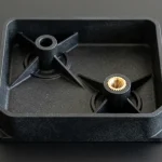
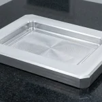
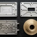
Precision CNC Machining Services & Custom Machined Parts
At AS Prototypes, our in-house Computer Numerical Control (CNC) facility and 20°C Zeiss metrology lab in Shenzhen deliver precision CNC machining services from single prototypes to production runs. We hold critical features to ±0.010 mm (±0.0004″), complete rapid prototypes in 4–8 business days ex-factory (plus 3–5 days air transit), and provide 24-hour Design for Manufacturability (DFM) reviews.
3, 4 & 5-Axis Milling & Turning
±0.010 mm Critical-Feature Tolerances
4 – 8 Business Days Ex-Factory Prototyping
50+ Verified Engineering Alloys & Polymers
Coordinate Measuring Machine (CMM) Metrology Verification (Available Upon Request)
Comprehensive Precision CNC Machining Processes
Our in-house machine shop integrates Brother, Fanuc, Mazak, and AFMING CNC milling centers, Takisawa and Star turning systems, Sodick and Makino Electrical Discharge Machining (EDM), and Okamoto/Palmary grinding centers:
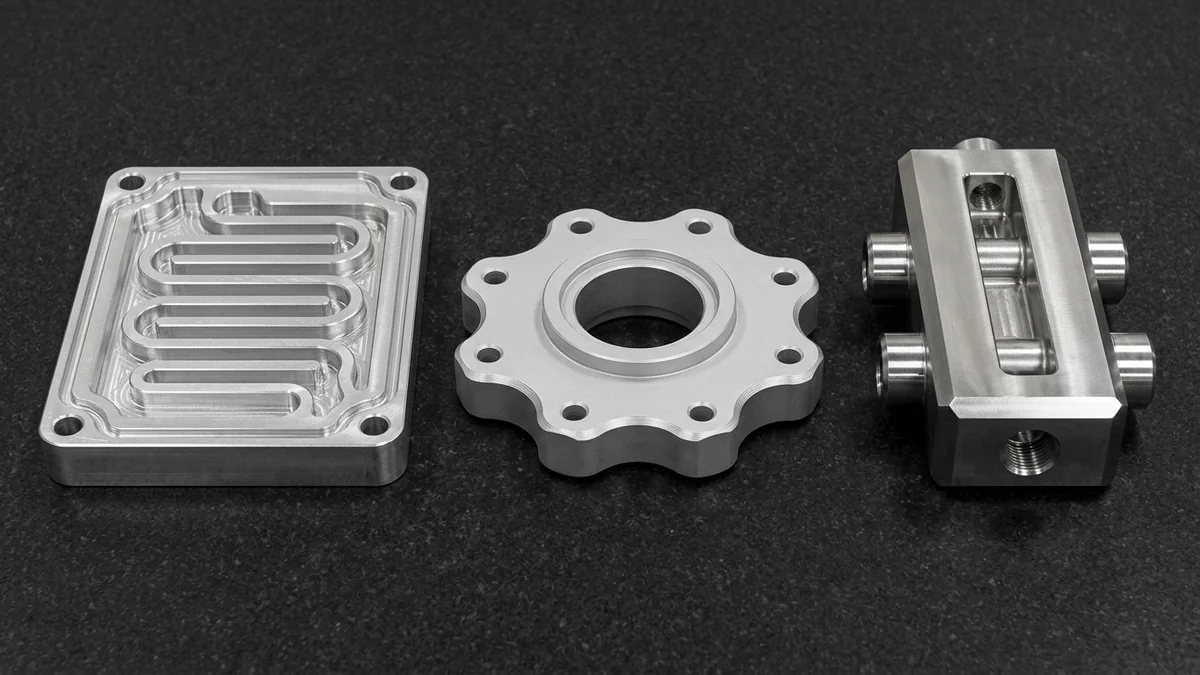
Precision CNC Milling Services
High-speed Brother, Fanuc, and Mazak 3-axis and 4-axis vertical machining centers (12,000–24,000 RPM) for pockets, manifolds, cold plates, and precision prismatic hardware.
- Critical / General Tol.:±0.010–±0.020 mm / ISO 2768-mK
- Max Travel Envelope:1,050 × 530 × 510 mm
- Surface Roughness:Ra 0.8 – 3.2 μm (32–125 μin)
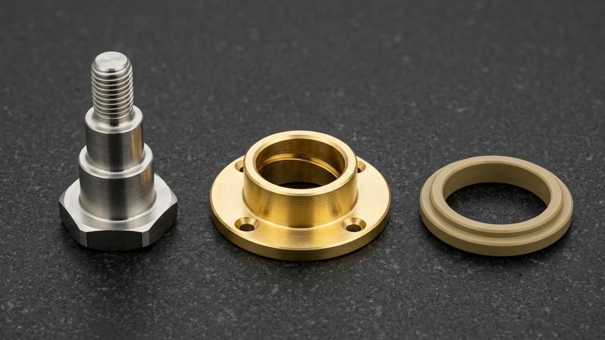
CNC Turning & Lathe Machining
Slant-bed Takisawa and SYNTEC CNC turning centers plus live-tooling mill-turn lathes for concentric stepped shafts, flanged bushings, threaded studs, and seal rings.
- Drawing Tolerance:±0.010 mm to ±0.020 mm
- Max Turning Envelope:Ø350 × 400 mm / Ø300 × 550 mm
- Surface Roughness:Ra 0.4 – 1.6 μm (16–63 μin)
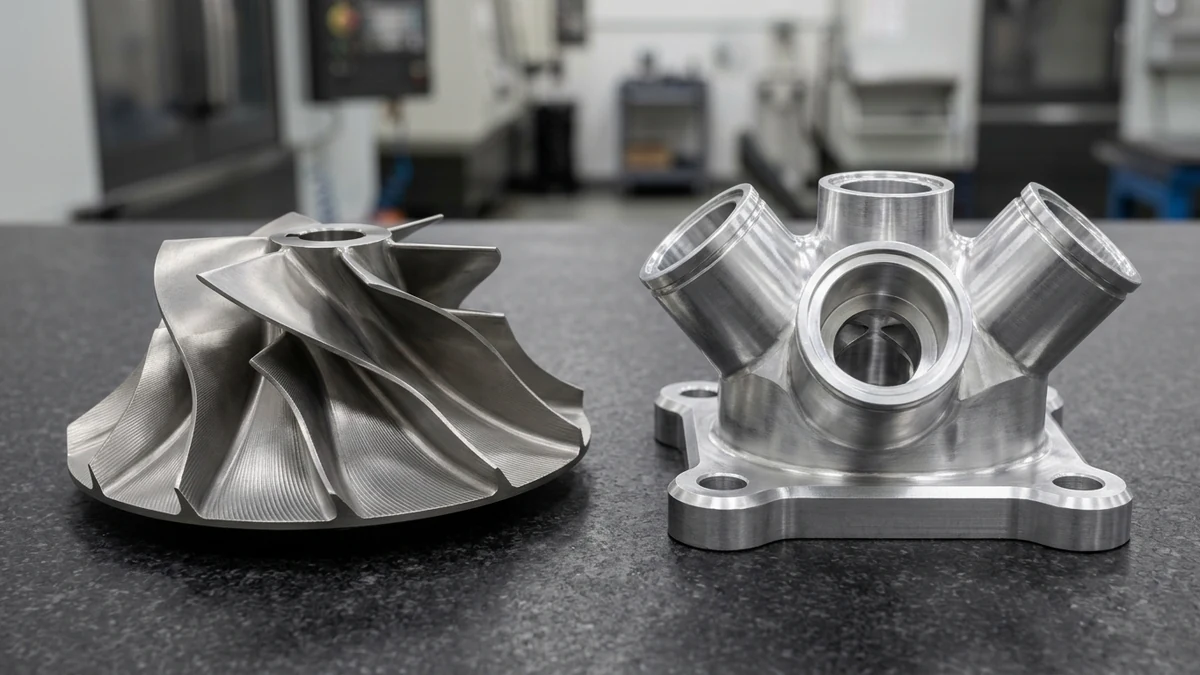
5-Axis Simultaneous CNC Machining
Trunnion 5-axis machining (AFMING GMU-400, 20,000 RPM HSK-A63, Heidenhain TNC) dedicated to centrifugal impellers, compound-angle fluid manifolds, and sculpted contours.
- Precision Tolerance:±0.010 mm to ±0.015 mm
- Trunnion Table Envelope:Ø450 × 350 mm (5-axis continuous)
- Setup Advantage:5 sides finished in 1 datum setup
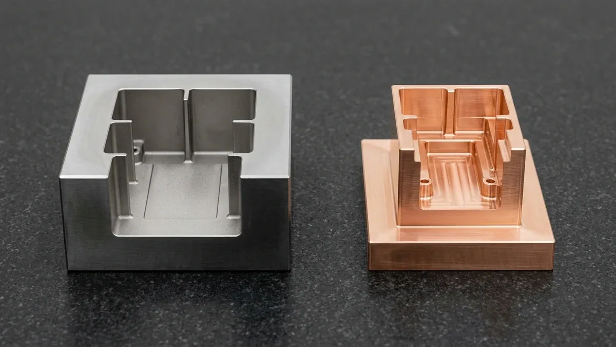
Wire & Sinker EDM
Sodick linear-motor wire EDM and Makino CNC sinker EDM cutting hardened tool steels (55–65 HRC) and carbide with zero mechanical cutting force.
- EDM Tolerance:±0.005 mm wire (±0.010 mm sinker)
- Min Internal Radius:R ≥ 0.07 mm (0.10–0.25 mm wire)
- Skim-Cut Finish:Ra 0.2–0.4 μm (1 rough + 3–4 skims)
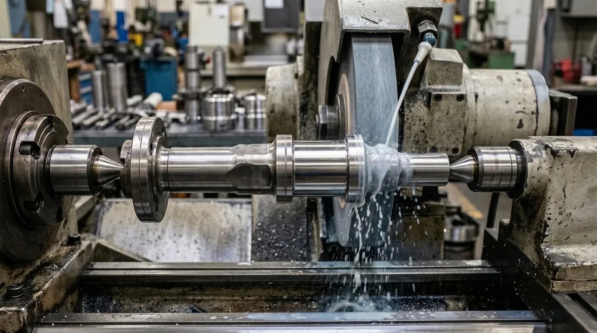
Surface & Cylindrical Grinding
Okamoto surface grinders (600 × 300 mm) and Palmary cylindrical grinders (Ø320 × 500 mm) delivering micron-level flatness, cylindricity, and fine ground finishes.
- Grinding Tolerance:±0.005 mm (±0.0002″)
- Flatness / Parallelism:≤ 0.005 mm / 100 mm (0.0002″)
- Ground Roughness:Ra 0.1 – 0.2 μm (4–8 μin)
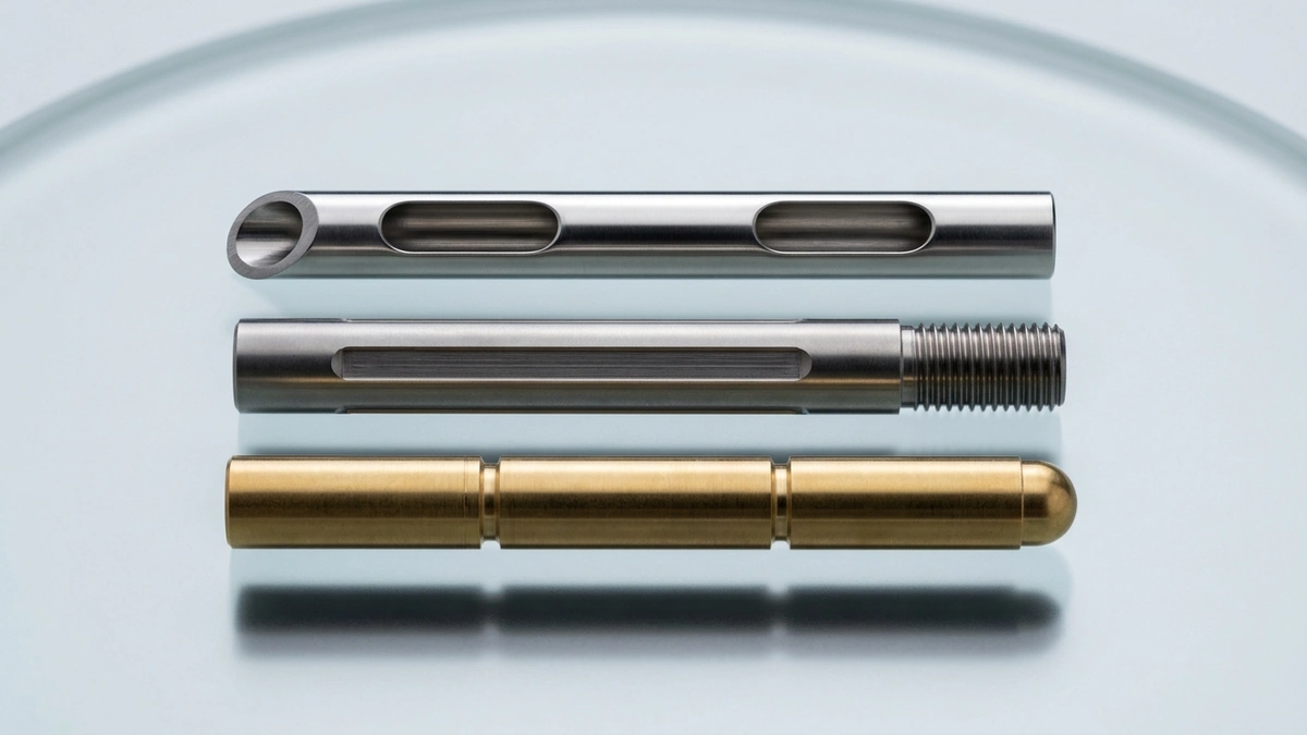
Swiss-Type CNC Micro Machining
Multi-axis Star Swiss lathes with sliding headstocks and tungsten carbide guide bushings for micro-diameter pins, slotted cannulas, bone screws, and sensor contacts.
- Micro Tolerance:±0.005–±0.010 mm (±0.0002″–±0.0004″)
- Bar Capacity:Ø0.5 mm to Ø32 mm (0.020″–1.25″)
- Slender Ratio:Low-deflection support up to 20:1 L/D
CNC Machining Materials & Surface Finishing Solutions
AS Prototypes stocks and machines over 50 engineering metals, high-performance polymers, and specialty alloys. Incoming billets, bars, and plates undergo lot-level verification against authentic Mill Test Reports (MTR) and ASTM E18 Rockwell hardness checks:
Precision Machining Metals
Traceable raw metals with full chemical composition and mechanical property documentation:
- Aluminum: 6061-T6, 7075-T651, 2024-T351, 5052-H32, 6063, MIC-6
- Stainless Steel: 304/304L, 316/316L, 17-4PH, 303, 440C
- Alloy & Tool Steels: 4140, 4340, D2, A2, H13, S136 (up to 55–60 HRC)
- Titanium & Superalloys: Ti-6Al-4V Gr 5, Inconel 718
- Copper & Brass: C110 Copper, C3604 Brass, Phosphor Bronze
- Light Alloys: Magnesium AZ31B, Zinc Alloys
Engineering Plastics
High-modulus and biocompatible polymers machined with specialized high-rake carbide tooling:
- POM (Acetal / Delrin): Homopolymer & Copolymer
- PEEK: Virgin PEEK, 30% Glass-Filled, 30% Carbon-Filled
- PTFE (Teflon) & UHMW-PE: Ultra-low friction & chemically inert
- Nylon (PA6, PA66, PA+GF30): High toughness & wear resistance
- PC & PMMA (Acrylic): Optical clarity, impact strength (PC) & UV stability (PMMA)
- Specialty: Ultem (PEI 1000), Torlon, PPS, Bakelite, FR-4
Surface Finishing & Coatings
Full suite of post-machining treatments with dimensional masking on precision bores and threads:
- Anodizing: MIL-A-8625 Type II (Color) & Type III (Hardcoat 50 μm, 450–550 HV0.05)
- Plating: Electroless Nickel (ASTM B733), Hard Chrome, Zinc
- Bead Blasting: Uniform matte texture (#80 to #150 glass bead)
- Passivation: ASTM A967 citric & nitric passivation (~0.002 μm zero buildup)
- Polishing & Marking: Mechanical mirror polish, PC vapor polish, laser marking
- Protective Coatings: Alodine 1200S / SurTec 650, black oxide, powder coat, PVD
What Tolerances Can CNC Machining Hold? ISO 2768-mK Standards
CNC machining tolerance capability depends on process kinematics and material rigidity. Our default general-tolerance standard for undimensioned features on CNC-machined metals and rigid engineering plastics is ISO 2768-mK (with ISO 2768-c applied to soft PTFE). Critical bearing bores, dowel fits, and journals are directly dimensioned at ±0.010–±0.020 mm (±0.0004″–±0.0008″).
For ultra-tight datum slots, hardened splines, and bearing journals, Sodick Wire EDM, Star Swiss turning, and CNC grinding hold ±0.005 mm (±0.0002″). Review our CNC machining tolerances and stack-up guide, precision turning and Swiss lathe tolerance breakdown, and precision machining processes overview.
| Basic Size Range (mm) | Fine (f) [Tight Spec Option] | Medium (m) [Metals & Rigid Plastics Baseline] | Coarse (c) [Soft PTFE] | Very Coarse (v) |
|---|---|---|---|---|
| 0.5 up to 3 | ±0.05 | ±0.10 | ±0.20 | — |
| over 3 up to 6 | ±0.05 | ±0.10 | ±0.30 | ±0.50 |
| over 6 up to 30 | ±0.10 | ±0.20 | ±0.50 | ±1.00 |
| over 30 up to 120 | ±0.15 | ±0.30 | ±0.80 | ±1.50 |
| over 120 up to 400 | ±0.20 | ±0.50 | ±1.20 | ±2.50 |
| over 400 up to 1000 | ±0.30 | ±0.80 | ±2.00 | ±4.00 |
| over 1000 up to 2000 | ±0.50 | ±1.20 | ±3.00 | ±6.00 |
| over 2000 up to 4000 | — | ±2.00 | ±4.00 | ±8.00 |
| Material Category | General Tolerance Standard | Direct-Dimensioned Tolerance (mm / in) | Tight-Tolerance Capability (mm / in) | Recommended Machining Process |
|---|---|---|---|---|
| Rigid Engineering Plastics (POM, PEEK, PC, ABS; soft PTFE: ISO 2768-c) | ISO 2768-mK | ±0.050 mm (±0.0020″) | ±0.030 mm (±0.0012″) | High-Speed 3/4-Axis Milling |
| Precision Metals (Aluminum, Brass, Copper, Stainless) | ISO 2768-mK | ±0.020 mm (±0.0008″) | ±0.010 mm (±0.0004″) | 3/4-Axis Milling & CNC Turning |
| Complex Impellers, Compound Manifolds & Titanium | ISO 2768-mK | ±0.015 mm (±0.0006″) | ±0.010 mm (±0.0004″) | Simultaneous 5-Axis Milling |
| Ultra-Precision Bores, Micro Shafts & Splines | Custom Geometric Dimensioning and Tolerancing (GD&T) | ±0.010 mm (±0.0004″) | ±0.005 mm (±0.0002″) | Wire EDM, Grinding & Swiss Turning |
Design for Manufacturability (DFM) Guidelines for CNC Machining
Designing CNC machined components with shopfloor kinematics in mind reduces cycle times, minimizes carbide tool deflection, and lowers unit manufacturing costs. Review our core engineering rules:
Maximize Internal Corner Radii
Design internal vertical corners with the largest allowable radius (ideally R ≥ 1/3 cavity depth, or R ≥ 1.15 × cutter radius). Standardizing radii across pockets lets CAM programmers run a single rigid end mill without corner chatter.
Limit Depth of Pockets & Holes
Limit pocket depth to 3–4 times pocket width to prevent L³/D⁴ cutter deflection. Keep standard carbide drilled holes within 4–5 times diameter (up to 10×D with parabolic peck drilling) using standard metric drill sizes.
Enforce Minimum Wall Thickness
Maintain a minimum wall thickness of 0.8–1.0 mm for aluminum and steels, and 1.5 mm for engineering plastics. Adequate wall rigidity prevents harmonic chatter and post-machining residual stress distortion.
Standardize Thread Specifications
Specify standard coarse threads (e.g., M2 to M16) with 1.5× to 2.0× nominal diameter effective engagement (2.5×D maximum). On blind tapped holes, leave ≥ 0.5×D unthreaded bottom pilot relief for chip evacuation.
Opt for Laser Marking
Use fiber laser marking or electrochemical etching for serial numbers and part IDs instead of micro-milling. When milled text is required, specify recessed sans-serif characters (≥ 0.5 mm stroke width, ≤ 0.3 mm depth).
Minimize Setups & Re-Fixturing
Align features to orthogonal datum planes to minimize manual flips. For multi-sided ports, leverage 4-axis indexing and 3+2 positional setups (simultaneous 5-axis for compound contours) to eliminate datum shift stack-up.
| DFM Design Feature | Recommended Geometry (mm / Ratio) | Extreme Feasibility Limit | Shop-Floor Physics & Cost Impact / When to Apply |
|---|---|---|---|
| 1. Internal Vertical Pocket Corners | R ≥ 1/3 × Pocket Depth (or R ≥ 1.15 × Cutter Radius) | R0.5 mm (Shallow) / Dog-Bone Relief | Allows continuous circular arc milling without cutter deceleration chatter or secondary sinker EDM burns. |
| 2. Pocket Depth-to-Width Ratio | Depth ≤ 4 × Pocket Width (Al) / ≤ 3 × Width (Steel) | Up to 6:1 with Reduced Feed & Shrink-Fit Holders | Cantilever deflection scales with L³/D⁴; shallower pockets prevent wall taper and premature flute chipping. |
| 3. Minimum Wall Thickness | ≥ 0.8–1.0 mm (Metals) / ≥ 1.5 mm (Polymers) | 0.5 mm (Local Short Metal Rib Sections Only) | Prevents harmonic vibration during high-speed roughing and elastic springback distortion upon unclamping. |
| 4. Blind Tapped Thread Depth | 1.5 × D to 2.0 × D Effective Thread Engagement | 2.5 × D Max (+ ≥ 0.5 × D Unthreaded Pilot Relief) | First 6 threads carry >85% of axial load; deeper blind tapping increases chip packing and tap breakage risk. |
| 5. Drilled Hole Aspect Ratio (L/D) | Depth ≤ 4–5 × Diameter (Standard Carbide Drill) | Up to 10 × D (Parabolic Flute Peck Drilling) | Standard stub drills maintain true position without wandering; angled entry faces require flat spot-milling first. |
| 6. Setup Consolidation & Datums | 1 to 2 Orientations (3/4-Axis Vise or 3+2 Indexed) | Simultaneous 5-Axis for Compound Contours | Minimizing manual re-clamping eliminates fixture datum shift and substantially reduces non-cutting setup overhead. |
| 7. Floor Fillet Radius | Standard Flat End Mill (0 mm) or Bull-Nose R0.5 / R1.0 mm | Non-Standard Custom Ground Corner Radii | Standardizing floor radii to off-the-shelf carbide bull-nose cutters avoids custom tool grinding lead time. |
| 8. Selective Critical Tolerancing | ISO 2768-mK General; ±0.010–0.020 mm Only on Fits | ±0.005 mm (Requires Wire EDM / Swiss / Grinding) | Restricting tight tolerances to functional bearing bores and dowel pins avoids 2×–4× inspection and cycle-time surcharges. |
| Surface Roughness Tier | Target Ra / Rz Value (μm / μin) | Machining / Finishing Process | Visual & Tactile Appearance | Recommended Engineering Use Case / When to Choose |
|---|---|---|---|---|
| Tier 1: Standard As-Machined | Ra 3.2 μm (125 μin) | Rz 12.5 μm | Standard high-efficiency milling / turning feed rate | Visible directional toolpath witness marks | Default commercial finish for non-mating brackets, structural frames, and internal enclosures. |
| Tier 2: Fine Precision Machined | Ra 1.6 μm (63 μin) | Rz 6.3 μm | Dedicated finishing pass with wiper insert / high RPM | Smooth satin metallic sheen with faint cutter lines | Precision mating faces, bolted flanges, bearing housing seats, and general cosmetic hardware. |
| Tier 3: High-Grade Sealing Finish | Ra 0.8 μm (32 μin) | Rz 3.2 μm | Fine step-over ball/flat finishing + micro-grain carbide | Near-mirror smooth surface; tool marks barely perceptible | Static O-ring sealing grooves, hydraulic manifold blocks, and high-precision sliding gibs. |
| Tier 4: Superfinished / Ground | Ra 0.4 to 0.1 μm (16–4 μin) | Precision surface/cylindrical grinding, wire EDM skims, or lapping | Specular ground or fine spark-skimmed finish | Dynamic rotary shaft journals, high-vacuum sealing flanges, and optical mounting datums. |
Shopfloor Quality Control & Coordinate Measuring Machine (CMM) Metrology Lab
Every production run undergoes strict in-process probing and climate-controlled metrology verification before ultrasonic cleaning, protective packaging, and ex-factory release:
In-Situ Spindle Touch Probes
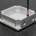
Renishaw spindle touch probes on our CNC centers perform automated workpiece datum alignment and in-process critical feature checks prior to unclamping.
Coordinate Measuring Machine (CMM) Metrology Lab
Our climate-controlled inspection lab maintains 20°C ± 1°C, housing a Zeiss bridge CNC CMM and 2.5D optical Video Measuring Systems (VMS) for micron-level volumetric verification.
First Article Inspection (FAI)
Comprehensive First Article Inspection (FAI) reports—available upon request—with ballooned 2D prints, Zeiss CMM coordinate logs, and ISO 4287 contact stylus surface roughness profiles.
Material Traceability (MTR)
Complete raw material lot traceability backed by authentic Mill Test Reports (MTR) documenting chemical composition and tensile properties, plus ASTM E18 Rockwell hardness verification.
Optimize Your CAD Machinability Before Tooling Up
Our in-house engineering team conducts detailed Design for Manufacturability (DFM) reviews on every 3D CAD model within 24 hours—optimizing internal corner radii, cavity depth ratios, and wall thickness to eliminate costly tool deflection and reduce unit production costs.
Frequently Asked Questions About CNC Machining Services
Technical specifications, ex-factory turnaround lead times, quality documentation, and RFQ submission procedures:
What types of precision CNC machining services does AS Prototypes provide?
We provide 3-axis and 4-axis vertical CNC milling, simultaneous 5-axis trunnion milling, CNC turning with live tooling, Star Swiss micro-machining, Sodick wire EDM, Makino sinker EDM, and Okamoto/Palmary grinding. We support 1-off rapid prototypes (4–8 business days ex-factory) through batch production runs (7–30 business days ex-factory, excluding 3–5 days air transit).
What machining tolerances can AS Prototypes achieve for custom CNC parts?
Undimensioned features follow ISO 2768-mK for CNC-machined metals and rigid engineering plastics (ISO 2768-c for soft PTFE). Directly dimensioned mating bores and bearing fits hold ±0.010–±0.020 mm (±0.0004″–±0.0008″) on our milling and turning centers, while Sodick wire EDM, Star Swiss lathes, and CNC grinders achieve ±0.005 mm (±0.0002″) and Ra 0.2 μm (8 μin).
What engineering materials and surface finishes are supported?
We machine over 50 traceable metals and polymers, including aluminum (6061-T6, 7075-T651, 2024, 5052), stainless steels (304, 316L, 17-4PH), tool steels (D2, H13, S136), Ti-6Al-4V titanium, Inconel 718, C3604 brass, C110 copper, POM, PEEK, PTFE, PC, and PMMA. Post-machining finishes include MIL-A-8625 Type II/III anodizing, electroless nickel, ASTM A967 passivation, bead blasting, powder coating, and laser marking.
How does AS Prototypes inspect and guarantee machined part quality?
Every batch undergoes in-process probing and final inspection inside our 20°C ± 1°C climate-controlled metrology laboratory. Equipment includes a Zeiss bridge CNC CMM, 2.5D optical Video Measuring Systems (VMS), TESA height gauges, ASTM E18 Rockwell hardness testers, and Mitutoyo ISO 4287 contact stylus roughness testers. Full First Article Inspection (FAI) reports and Mill Test Reports (MTR) are provided upon request.
What is the typical turnaround time and how do I request an instant RFQ quotation?
As-machined rapid prototypes complete ex-factory production and inspection in 4 to 8 business days, while anodized or plated prototypes take 7 to 12 business days ex-factory (DHL/FedEx/UPS international air transit adds 3 to 5 business days). Upload your 3D CAD files (STEP, IGES, Parasolid, or SolidWorks) and 2D PDF drawings via our Contact & RFQ Portal for a 24-hour DFM quote.
Can AS Prototypes sign a Non-Disclosure Agreement (NDA) before reviewing my CAD files?
Yes, absolutely. We treat intellectual property protection and proprietary hardware designs with strict legal confidentiality. Our team routinely executes mutual or client-provided Non-Disclosure Agreements (NDAs) prior to receiving 3D CAD models, 2D tolerance drawings, or bill-of-materials documentation.
Ready to Validate Your Precision CNC Machined Parts?
Upload your 3D CAD models (STEP, IGES, Parasolid) and 2D engineering drawings. Our in-house engineering team will review your toolpaths, provide actionable DFM feedback, and return an itemized custom quotation within 24 hours.
✓ 100% In-House Fleet
✓ ISO 2768-mK Tolerances
✓ Zeiss CMM Metrology
✓ Full MTR Material Traceability