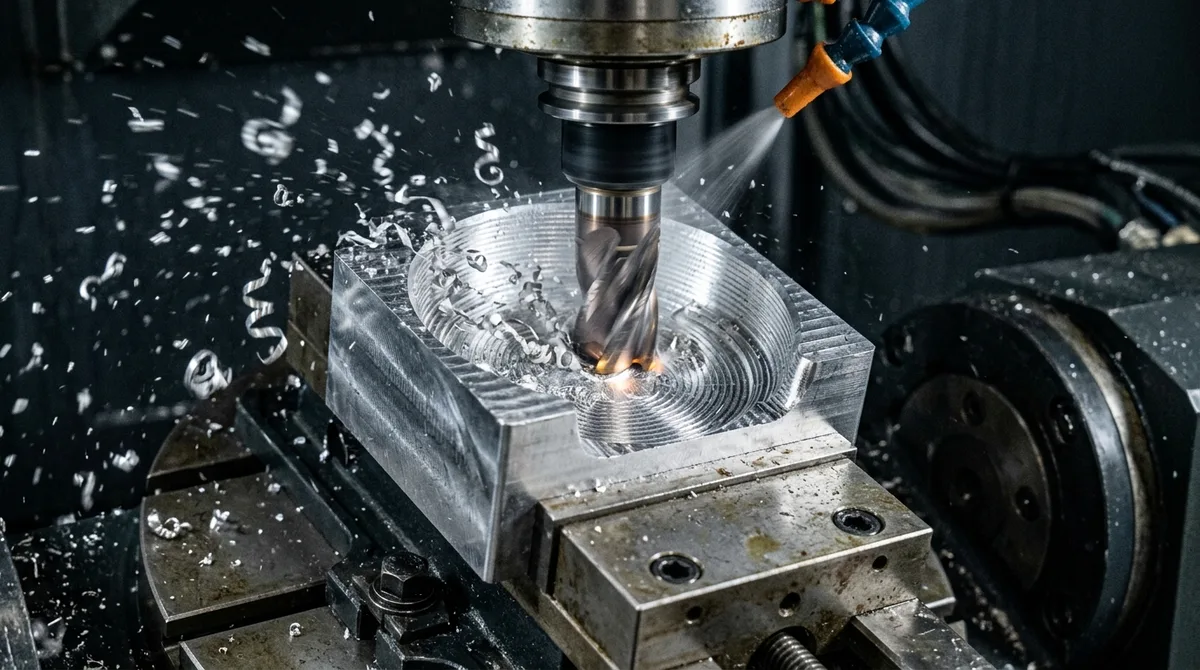
Deploying advanced metal machining strategies is the single most critical factor in achieving high-precision (±0.010mm) part precision, mitigating thermal tool deflection, and slashing production cycle times across complex alloy fabrication. From structural 7075-T6 aerospace airframes to hardened tool steels and refractory titanium, modern high-velocity subtractive fabrication demands far more than traditional linear milling passes. In our precision CNC machining facility, synchronizing dynamic trochoidal toolpaths, chip thinning kinematics, and multi-axis workholding ensures parts meet rigorous tolerances without excessive cutter wear.
1. The Physics of High-Efficiency Metal Machining Strategies
Traditional legacy milling relied on heavy radial engagements with low axial depths of cut, concentrating devastating thermal and mechanical shocks on the tip of the cutting tool. Modern High-Efficiency Milling (HEM) inverts this dynamic:
- Full Axial Depth of Cut (Ap): Utilizing up to 2.0× to 3.0× the cutter diameter along the tool’s flutes, distributing mechanical wear uniformly across the entire carbide cutting edge rather than degrading the corner radius.
- Light Radial Engagement (Ae): Maintaining radial stepovers between 5% and 15% of cutter diameter. This dramatic reduction keeps tool engagement angles small (typically under 45°), allowing cutting flutes to cool between successive chip impacts.
- Radial Chip Thinning Compensation (RCTC): Because light radial engagements produce a chip thickness significantly thinner than the programmed feed per tooth, CAM systems automatically accelerate feed rates (often by 200% to 300%) to maintain true optimum chip load (h_max), dramatically increasing material removal rates (MRR).
- Constant Tool Engagement Angle (TEA): Proprietary adaptive pocketing algorithms ensure the cutter never plunges into 90° internal corners, preventing momentary spike overloads and cutter breakage.
| Machining Strategy | Radial Engagement (Ae) | Axial Depth (Ap) | Cutting Speed (Vc) | Primary Advantages & Ideal Use Cases |
|---|---|---|---|---|
| Conventional Roughing | 50% – 75% D | 0.5 – 1.0× D | Standard Baseline | Basic prismatic slabs; high tool tip wear |
| High-Efficiency Milling (HEM) | 5% – 15% D | 2.0 – 3.0× D | 150% – 250% Baseline | Deep pocketing, aerospace bulkheads, hard alloys |
| High-Feed Milling (HFM) | 60% – 80% D | 5% – 10% D | Extreme Feed Rates | Large mold cavity roughing, high MRR in P20/NAK80 |
| Trochoidal Milling | Dynamic (Roll-in) | Up to 4.0× D | 200% Baseline | Narrow slots, titanium pocketing, thin wall pockets |
2. Tooling Geometry, Substrates & PVD Coatings
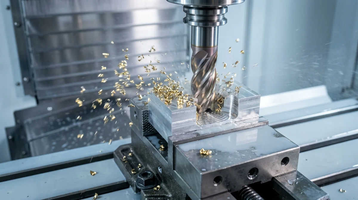
Executing high-performance metal machining strategies requires pairing machine kinematics with cutting tool metallurgy engineered for specific alloy categories:
A. Micro-Grain Solid Carbide Substrates
Sub-micron tungsten carbide substrates with 8% to 12% cobalt binder deliver the ideal equilibrium between transverse rupture strength (resisting chipping under intermittent cuts) and extreme hardness (up to 1800 HV).
B. Advanced PVD Coatings for Thermal Protection
- AlTiN / TiAlN (Aluminum Titanium Nitride): Forms a protective aluminum oxide ceramic layer at temperatures exceeding 800°C. The standard workhorse for pre-hardened steels, stainless steels (304/316L), and nickel superalloys.
- AlCrN (Aluminum Chromium Nitride): Superior hot hardness and oxidation resistance up to 1100°C, offering exceptional lubricity for high-temperature dry machining of abrasive tool steels.
- DLC (Diamond-Like Carbon) & CrN: Extremely low friction coefficients ((μ < 0.1\)) engineered exclusively for sticky non-ferrous alloys (such as 6061-T6 and cast aluminum A380), preventing built-up edge (BUE).
| Workpiece Material | Recommended Cutter Type | PVD / CVD Coating | Helix Angle | Coolant Strategy |
|---|---|---|---|---|
| Aluminum 6061 / 7075 | 3-Flute Polished Carbide | DLC / ZrN or Uncoated | 45° / 55° High Helix | Flood Coolant or High-Pressure MQL |
| Stainless Steel 316L / 304 | 4-Flute Variable Pitch | AlTiN / TiAlN | 38° – 41° Differential | High-Pressure Through-Spindle (70 Bar) |
| Hardened Tool Steel (H13 / D2) | 4 to 6-Flute Reinforced Core | AlCrN / TiSiN Nanocomposite | 35° Stable Helix | Cold Compressed Air Vortex Gun |
| Titanium Ti-6Al-4V | 5-Flute Unequal Spaced | AlTiSiN | 36° – 38° Pitch | High-Pressure Dedicated Emulsion |
3. Multi-Axis Workholding & Rigidity Dynamics
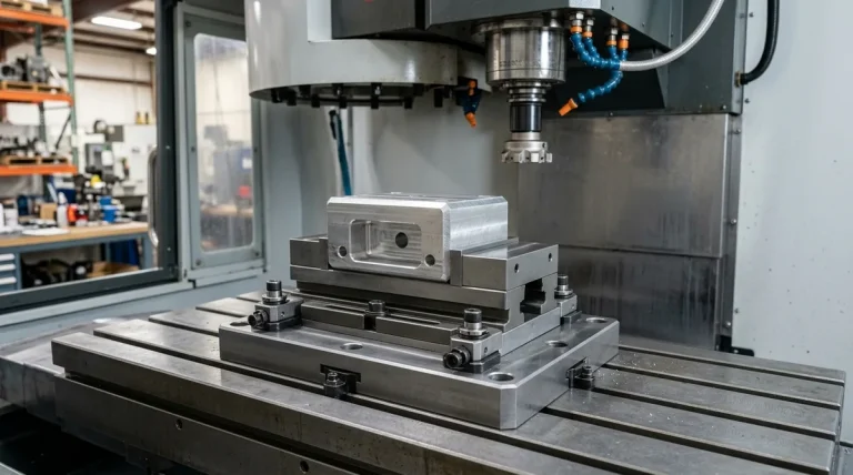
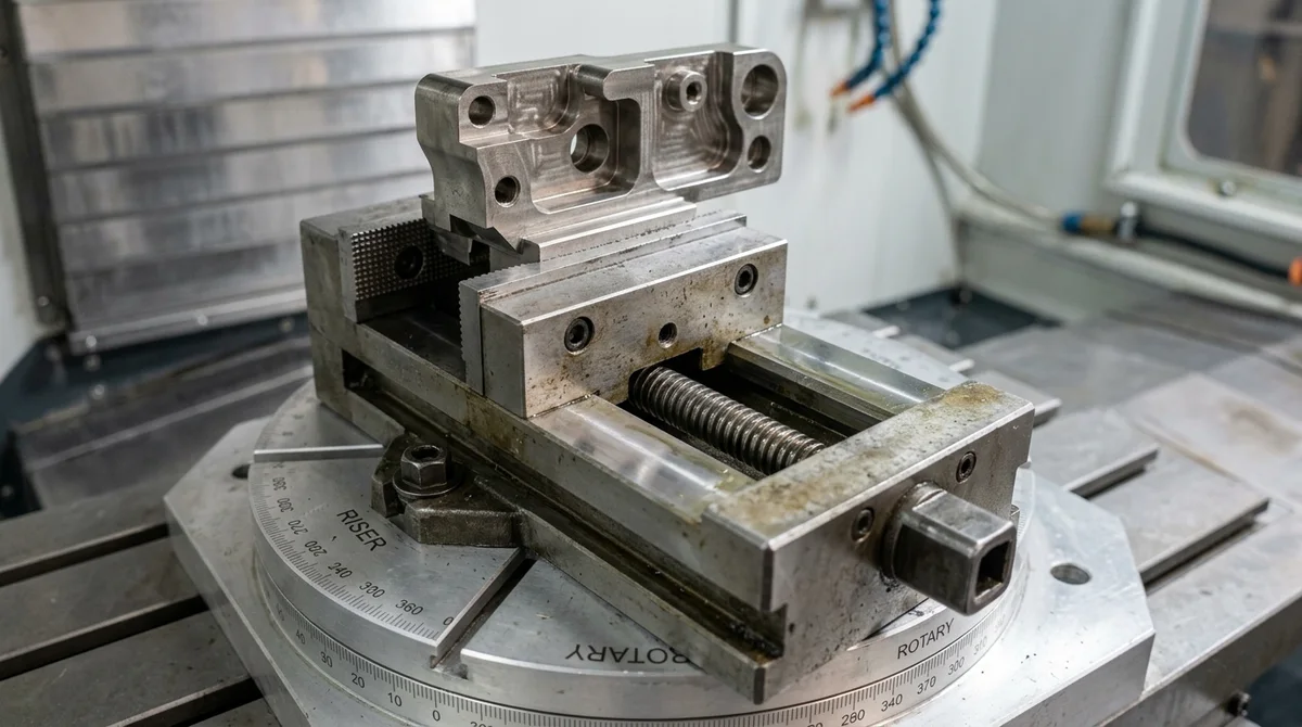
The finest CAM toolpaths cannot compensate for poor fixture rigidity. Cutting forces during aggressive machining induce microscopic vibration harmonics (chatter) that degrade surface finishes and destroy cutter flutes. In our facility, we deploy modular workholding tailored for 5-axis CNC machining:
- 5-Axis Self-Centering Vises: Precision vices (such as SCHUNK or Lang 52/96 systems) with dovetail pre-stamped gripping jaws require as little as 3 mm of bottom clamping stock, delivering over 14 kN of clamping force while providing complete spindle clearance around all 5 sides of the component.
- Hydraulic Chucks & Shrink-Fit Toolholders: Replacing standard ER collet chucks with shrink-fit or hydraulic toolholders reduces tool runout ((TIR < 0.003 mm), dampens harmonic vibration frequencies, and triples cutter service life during high-speed finishing.
- Custom Pie Jaws & Vacuum Fixtures: For thin-walled ring components or large delicate baseplates, contoured aluminum pie jaws or porous ceramic vacuum chucks distribute clamping forces uniformly across large contact areas, eliminating distortion upon clamp release.
4. Staged Roughing, Stress Relief & Finish Machining
To produce components adhering to ISO 2768-mK general tolerances or drawing-specified precision tolerances, our process engineers enforce a disciplined staged machining workflow:
- Primary Bulk Roughing: High-efficiency adaptive milling removes 80% – 85% of total stock, leaving a uniform 0.50 mm stock allowance on all faces and diameters.
- Stress Relaxation Unclamping: The part is completely unclamped from the primary vise and allowed to breathe, releasing latent rolling and forging residual stresses naturally before reclamping under light holding pressure.
- Semi-Finishing Pass: Removing remaining stock down to 0.10 mm with balanced toolpaths to establish consistent cutting tool pressure.
- Final High-Speed Finishing: Precision finish contours executed with dedicated fresh carbide cutters at elevated spindle speeds to achieve pristine mirror finishes (Ra 0.4 – 0.8 µm) and exact GD&T positional callouts.
High-Efficiency Milling (HEM) utilizes deep axial cuts (2x to 3x cutter diameter) with shallow radial engagements (5% to 15%), spreading heat and mechanical wear across the entire length of the cutter flute. This reduces localized tool wear, lowers cutting temperatures, and increases material removal rates by up to 200% compared to legacy shallow-step milling.
Tool chatter is eliminated by deploying variable-helix and differential-flute endmills that disrupt resonant harmonic frequencies, utilizing shrink-fit or hydraulic toolholders with sub-3-micron runout, reducing tool overhang stickout ratios to under 3:1, and executing constant engagement angle trochoidal toolpaths.
High-pressure coolant (70 to 100 bar) penetrates the thermal vapor barrier at the tool-chip interface, instantly lowering cutting temperatures. In deep pockets and stainless or titanium milling, it forcefully evacuates chips from the cut path, eliminating chip re-cutting and catastrophic cutter jamming.
Reading Tool Wear and Setting Tool-Life Limits
Predictable high-speed machining depends on retiring tools at defined flank wear limits, commonly 0.2 to 0.3 mm for finishing carbide tools, rather than running them until surface finish or dimensions begin to drift.
- Wear types: Flank wear, crater wear, built-up edge and chipping each point to a different cause, such as speed too high, feed too low or insufficient rigidity, and each calls for a specific correction.
- Tool-life limits by operation: Roughing tools tolerate more wear than finishing tools, so assign separate life limits and replace finishing cutters before wear affects tolerance-critical surfaces.
- Tool counters and probing: Machine tool-life counters and in-process touch probing detect drift before parts leave tolerance, and they remove dependence on visual inspection of the cutter.
- Coolant and chip evacuation: Consistent coolant pressure and chip clearing prevent recutting, which accelerates wear and leaves scratches that look like tool wear but originate from trapped chips.
Applying these limits keeps surface finish and dimensions stable across long runs, and it supports the staged roughing and finishing workflow because tools are matched to the operation that gives the best return on tool cost.
Optimize Your Metal Machining Projects with AS Prototypes
Leverage our advanced multi-axis machining centers, optimized CAM toolpath strategies, and deep material expertise to manufacture high-tolerance metal components at competitive cycle times.
Send us your STEP, IGES, or 2D technical drawings for a rapid DFM review and instant engineering quotation: