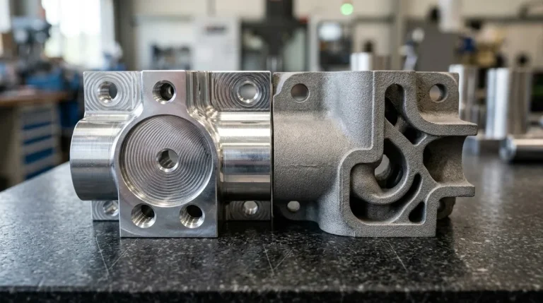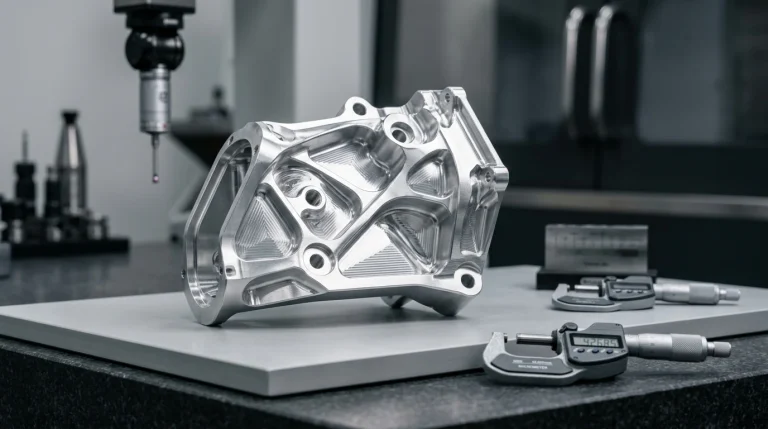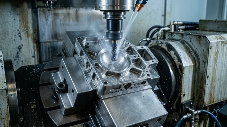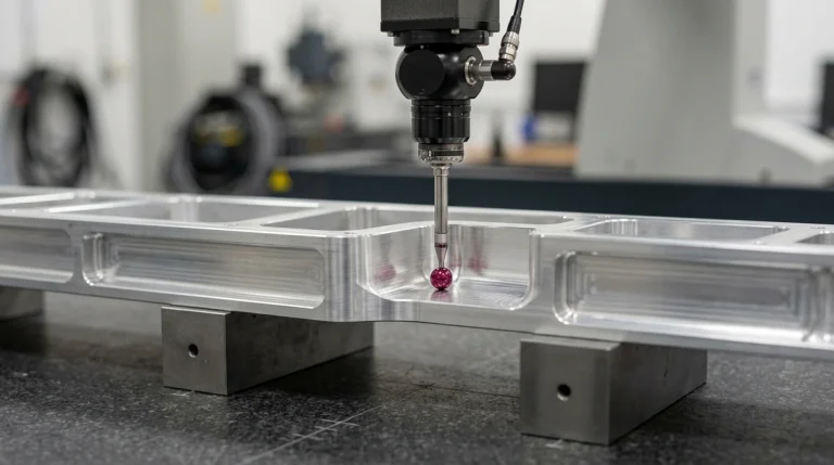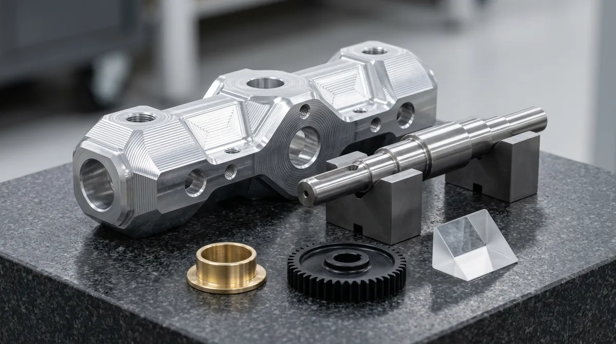
Prototype engineering represents the critical disciplined methodology that converts conceptual industrial designs into robust, production-viable hardware mechanisms. In an era where product lifecycles are compressed and commercial failure carries severe financial exposure, relying solely on theoretical computer simulations is a recipe for disaster. Physical prototypes reveal subtle structural resonance, thermal entrapment, friction wear, and assembly interferences that finite element analysis (FEA) models consistently overlook. In our comprehensive precision CNC machining and prototyping facility, deploying multi-axis CNC milling, polyurethane vacuum casting, and precision metrology empowers engineering teams to de-risk investments and dominate their markets.
1. Systematic Risk Mitigation and Defect Identification
The core philosophy of prototype engineering is to fail early, cheaply, and iteratively in the laboratory rather than catastrophically in high-volume production:
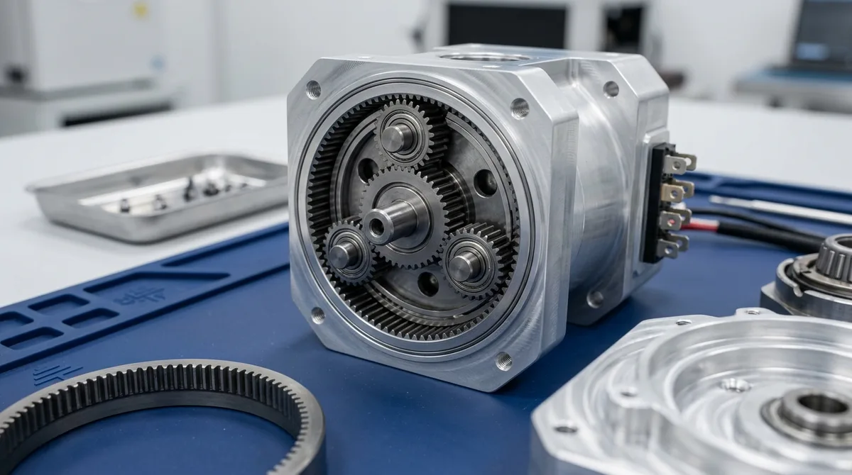
- Empirical Kinematic Validation: Complex multi-link robotic joints, gear trains, and latch mechanisms often encounter dynamic binding caused by cumulative tolerance stack-ups. Assembling physical prototypes identifies tight interfaces and backlash clearances instantly.
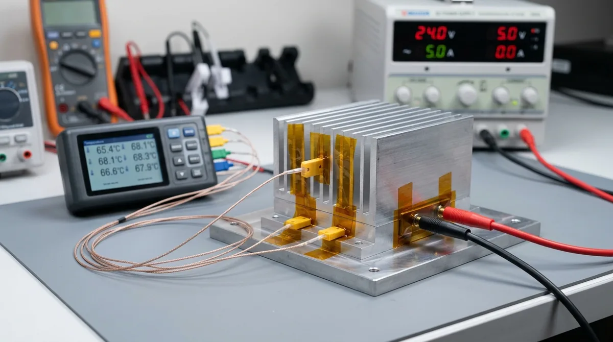
- Thermal and Environmental Reality: Heat dissipation from high-power LED drivers, power supplies, and EV battery cells can cause localized hot spots exceeding polymer glass transition temperatures. Testing functional metal prototypes under active thermal monitoring reveals required cooling fin spacing before tooling is cut.
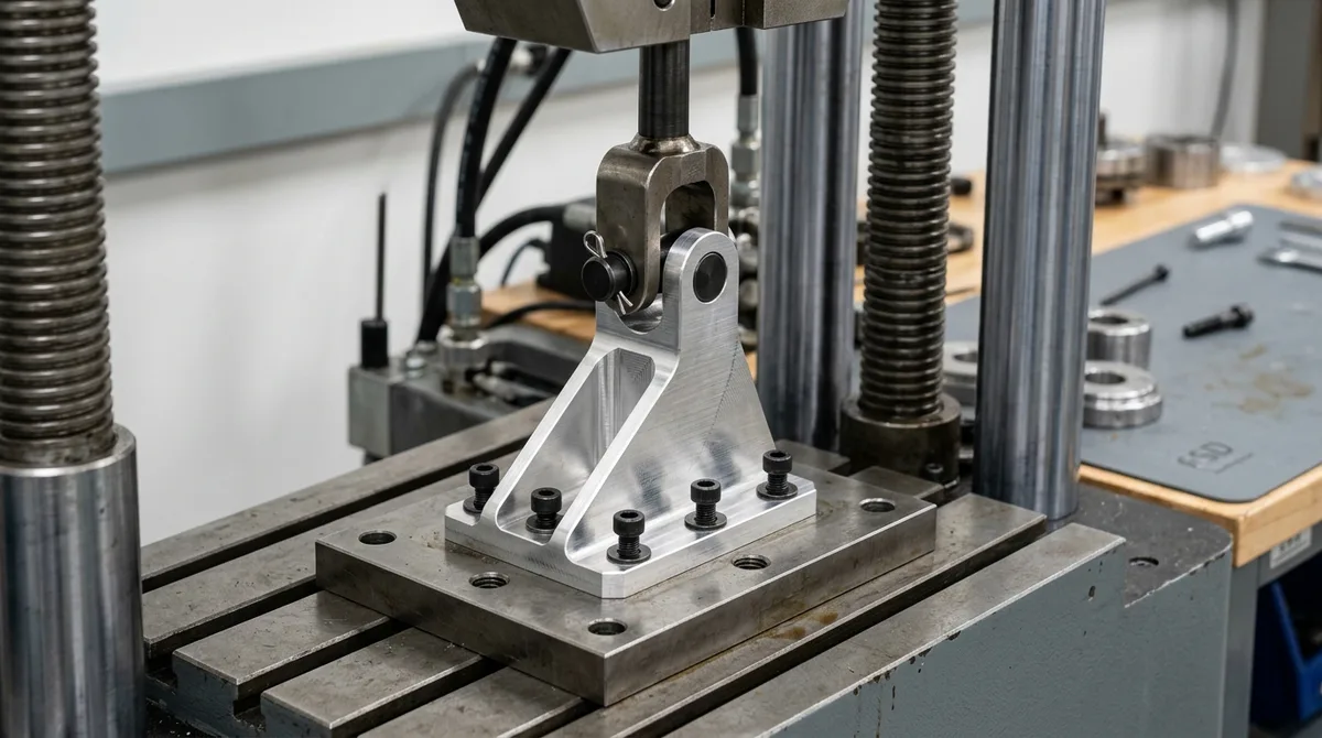
- Structural Stress Verification: Physical destructive pull testing and drop shock tests validate actual material yield strengths against theoretical simulation predictions.
2. Substantial Cost Avoidance via Proactive DFM
The cost of an engineering design modification increases by an order of magnitude (10x) with every subsequent step along the product commercialization roadmap:
| Development Phase | Engineering Activity | Relative Cost of Design Change | Typical Turnaround & Modification Time |
|---|---|---|---|
| Concept CAD Modeling | Modifying 3D parametric surfaces | 1x (Baseline) | Hours |
| Prototype Engineering | Machining CNC revisions & DFM fixes | ~10x | 4 – 8 Business Days |
| Production Tooling (Steel Molds) | Welding, EDM re-cutting, or re-sinking cavities | ~100x | 3 – 6 Weeks |
| Mass Production & Recall | Assembly stoppage, logistics recalls, scrap | 1,000x+ | Months (Catastrophic) |
DFM Case Study: Incorporating standard corner radii (R ≥ 1.6 mm), eliminating deep undercut features, and balancing plastic nominal wall thicknesses during prototype stages prevents expensive mold modifications and tool downtime.
3. Accelerated Time-to-Market via Rapid Sprints
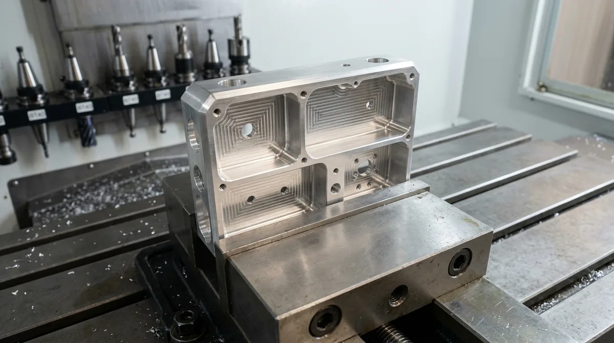
Speed to market often dictates market share dominance. By leveraging advanced 3-axis, 4-axis and 5-axis machining centers and flexible vacuum casting, hardware teams compress development schedules from months to days:
- Simultaneous Multi-Axis Prototyping: High-speed 3-axis and 4-axis CNC machining (5-axis available for complex contours) produces fully functional aerospace aluminum (6061-T6 / 7075-T6) and engineering plastic (POM-C / PEEK) parts in 4 to 8 business days, eliminating the 8-to-12-week wait for production tooling.
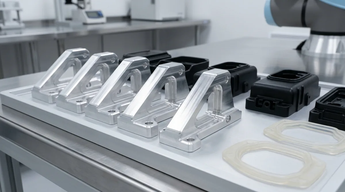
- Rapid Bridge Batches: When pre-series marketing samples or clinical trial units are needed, silicone rubber vacuum casting yields 20 to 50 parts in 7 to 12 business days, allowing pilot testing to proceed in parallel with steel mold fabrication.
4. Comprehensive Regulatory and Functional Verification
Hardware products must satisfy rigorous safety, electromagnetic, and environmental standards before international commercial sale:
| Industry Sector | Critical Prototype Engineering Test | Representative Material / Setup | Primary Regulatory & Functional Focus |
|---|---|---|---|
| Robotics & Automation | 100,000-cycle torsional fatigue & backlash drift | CNC 7075-T6 / 4140 Chromoly Steel | Harmonic gear life & dynamic positioning repeatability |
| Medical Instrumentation | Biocompatibility, autoclave sterilization cycles | Medical PEEK / 316LVM Stainless Steel | Biocompatibility evaluation & chemical resistance |
| Automotive Electronics | Thermal shock (-40°C to +125°C) & IP67 seal | ADC12 Die-Cast / 6061-T6 + EPDM gasket | FMVSS / ECE vibration & hermetic ingress protection |
| Consumer Devices | 1.5-meter repeated concrete drop testing | Polycarbonate / ABS-PC blend chassis | Snap-fit retention & structural impact survival |
5. Investor Confidence and Commercial Buy-In
Nothing convinces venture investors, corporate executives, or prospective retail buyers faster than a tangible, high-finish physical prototype:
- Exhibition-Grade Cosmetic Models: In our dedicated finishing department, prototypes receive Class-A high-gloss polishing, micro-bead blasting, Type II color anodizing, and custom Pantone polyurethane paint matching.
- Functional Field Proofs: Placing a functional, weight-authentic prototype into the hands of clinical surgeons or field technicians generates invaluable user ergonomics feedback that cannot be captured in a virtual presentation.
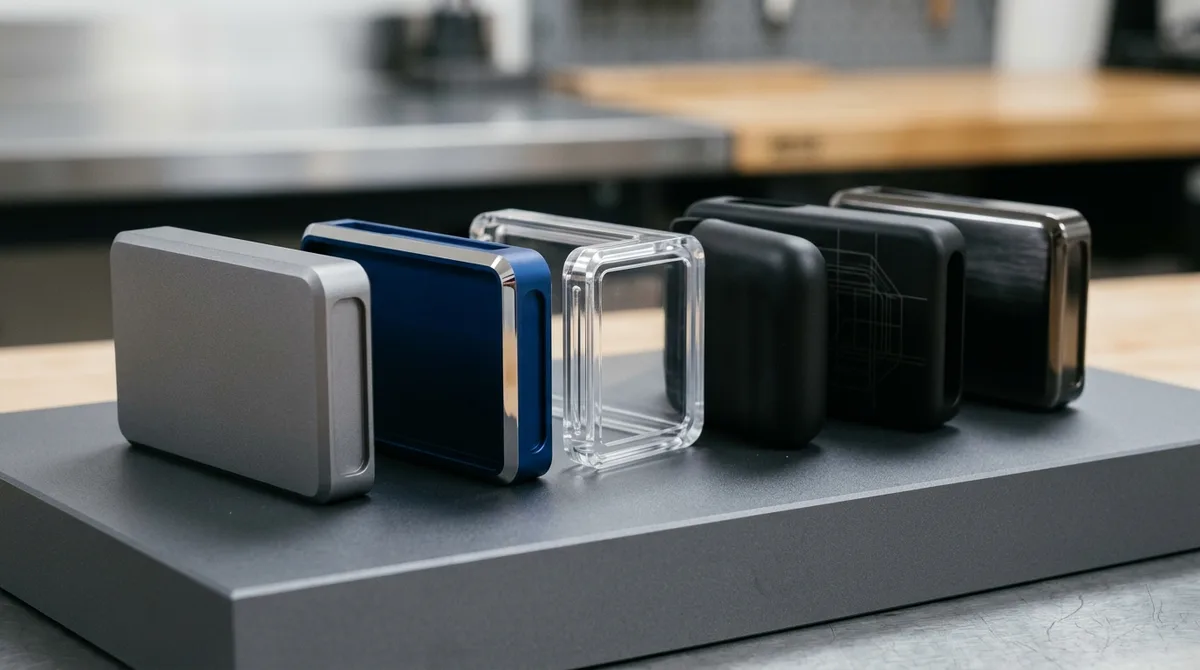
Building a Prototype Test Plan That Retires Risk in the Right Order
A prototype test plan retires the highest-impact risks first, with fit and function ahead of cosmetics and structure ahead of durability, so each build iteration answers one specific engineering question instead of repeating general checks.
- Risk ranking: Score every requirement by severity of failure and by uncertainty. High-severity, high-uncertainty items, such as a sealing interface or a load path, are tested on the first build.
- One hypothesis per build: Write a measurable hypothesis for each prototype, for example that a bracket deflects less than 0.5 mm under a defined load, so the result clearly confirms or rejects the design choice.
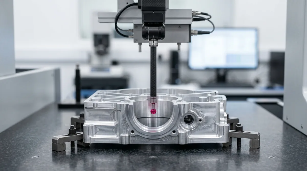
- Measure instead of judging: Replace visual opinions with measurements such as CMM reports, torque readings and leak-rate values, and store them with the build revision.
- Gate reviews and change lists: Freeze the list of design changes between builds so improvements can be traced to results and unexpected side effects are caught early.
Organizing the test plan this way keeps the schedule compressed without sacrificing evidence, because every prototype either removes a named risk or exposes one that can still be corrected while tooling changes remain inexpensive.
Frequently Asked Questions
Prototype engineering identifies design flaws, mold undercuts, and unmachinable features before steel injection molds or die-casting dies are manufactured. Catching and correcting a dimensional or draft angle issue during prototyping costs a small fraction of the effort, whereas modifying hardened production steel tools costs orders of magnitude more and delays schedules by weeks.
A typical hardware development cycle spans 6 to 12 weeks: 1 to 2 weeks for POC 3D printed models, 4 to 8 business days for EVT precision CNC functional prototypes, 7 to 12 business days for DVT vacuum-cast bridge batches and environmental testing, and final PVT tooling sign-off.
Prototype engineering utilizes production-grade materials to simulate real-world physics. Common metals include 6061-T6 and 7075-T6 aluminum, 303/304/316L stainless steel, and brass. Common engineering plastics include POM-C (Delrin), PEEK, Polycarbonate, and polyurethane casting resins simulating ABS, PP, and elastomers.
Accelerate Your Hardware with Precision Prototype Engineering
From functional CNC prototypes to bridge vacuum casting and full DFM review, our machine shop delivers unmatched agility, precision, and speed. Upload your 3D CAD models (STEP/IGES) for an instant confidential evaluation and quotation.