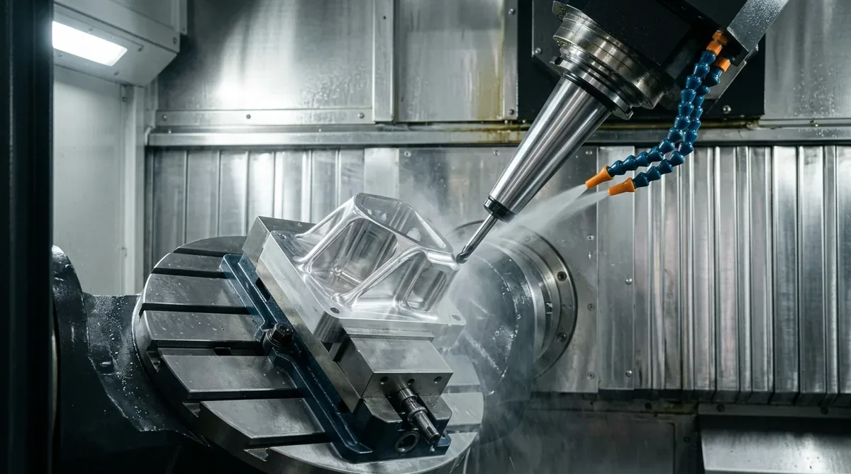
- Core Focus & DFM Scope: Actionable shop-floor engineering guidelines for smart prototype manufacturing, covering material selection, geometric tolerancing, and defect prevention.
- Achievable Tolerance Envelope: General features hold ISO 2768-mK; critical bearing bores, dowel pins, and mating datums hold ±0.010 to ±0.020 mm (±0.0004″ to ±0.0008″), with Wire EDM/grinding to ±0.005 mm (±0.0002″).
- Machining & Surface Integrity: High-speed 3-axis and 4-axis VMCs (with simultaneous 5-axis for complex contours) delivering as-machined Ra 0.8 µm (32 µin) to Ra 0.4 µm (16 µin) per ASME B46.1.
- Metrology & Process Control: On-machine spindle probing paired with 20°C (68°F) climate-controlled Zeiss CMM coordinate verification and calibrated Go/No-Go plug/ring gauges.
- Ex-Factory Turnaround: 4 to 8 business days for as-machined rapid prototypes; 7 to 12 business days for anodized, plated, or multi-operation production runs (excluding 3–5 days air transit).
⚙ Bottom Line Up Front (BLUF): Smart Prototype Manufacturing Architecture
Smart prototype manufacturing synthesizes physical CNC precision engineering with Industry 4.0 cyber-physical systems to eliminate the traditional trade-off between prototype turnaround velocity and micrometric dimensional repeatability. By deploying automated flexible manufacturing cells (FMCs), standardized pneumatic zero-point pallet clamping, and on-machine touch probe metrology (OMP), modern machine shops achieve ±0.010 mm feature tolerances across high-mix, low-volume (HMLV) engineering runs while compressing ex-factory prototyping delivery to 4 to 8 business days.
- Machine Shop Workhorse Allocation: While 5-axis simultaneous machining centers serve as strategic assets for sculptured impellers and multi-port valve manifolds, high-speed 3-axis and 4-axis vertical machining centers (VMCs) handle 75% to 85%+ of prototype structural brackets, electronic enclosures, and heat sinks with maximum spindle throughput.
- Closed-Loop Feedback: Optical and radio-transmission probing on CNC spindles measures intermediate roughing and semi-finishing datums, feeding real-time coordinate offsets via MTConnect/OPC-UA directly to CNC Fanuc, Siemens, or Heidenhain controllers to compensate for thermal drift and cutter wear dynamically.
- Production Reality: True shop-floor lead times reflect factory production and dimensional verification: DFM review within 24 hours, rapid prototypes within 4 to 8 business days, and bridge production batches (10 to 1,000+ units) delivered within 7 to 30 business days (plus 3 to 5 business days for international air express).
The Evolution from Artisan Machining to Cyber-Physical Prototyping
For decades, rapid prototype manufacturing depended heavily on artisan machine operators. Skilled machinists manually aligned raw billets in standard Kurt vises with dial test indicators, manually touched off end mills with feeler gauges, and calculated manual tool wear offsets after pulling hot parts from the machine enclosure. This legacy operational model introduced three compounding failure modes: operator-dependent setup variations, extended spindle downtime during dimensional inspection, and uncompensated thermal drift as ambient factory temperatures shifted throughout multi-hour machining cycles.
Smart prototype manufacturing fundamentally replaces these disjointed manual steps with a synchronized cyber-physical ecosystem. In an Industry 4.0 prototype facility, CAD/CAM models flow directly from digital design engineering repositories into automated CAM feature recognition software. Toolpaths are verified through digital twin simulation algorithms that validate dynamic tool clearance, verify spindle power curves, and predict cutting forces prior to releasing G-code to physical machine tools.
Furthermore, machine tools no longer function as isolated islands of automation. Each CNC center is integrated into an Industrial Internet of Things (IIoT) telemetry network. Spindle vibration sensors, bearing thermistors, linear scale encoders, and pneumatic pressure transducers stream sub-millisecond telemetry to edge computing gateways. When machining tough aerospace alloys such as Ti-6Al-4V Grade 5 or high-strength 7075-T651 aluminum, this real-time stream detects micro-chatter, predicts catastrophic tool chipping, and adjusts feed rates adaptively before dimensional tolerances degrade beyond drawing-specified limits.
Hardware Foundation: Kinematic Palletization and Zero-Point Clamping
The mechanical core of high-mix automated prototyping is the pneumatic zero-point clamping system. Standardizing pallet receivers across 3-axis VMCs, 4-axis horizontal machining centers (HMCs), and 5-axis continuous milling centers decouples part setup from valuable in-cut spindle time. Machinists secure raw stock or pre-machined billets onto modular aluminum soft jaws, dovetail fixtures, or vacuum chucks mounted on standard zero-point pallets outside the machine tool on dedicated granite metrology benches.
Once clamping torque and preliminary datums are established on the external setup station, the operator or an articulated robotic arm transfers the pallet into the machine tool receiver chuck. The pneumatic mechanism actuates hardened steel clamping balls around high-tensile pull studs, exerting positive mechanical pull-down force exceeding 25 kN with a mechanical repeatability of less than 0.002 mm (< 2 μm).
To maintain rigidity during heavy roughing cuts, the zero-point clamping interface must withstand the resultant cutting forces without elastic deflection or micro-slippage. The required holding force is governed by the cutting force equilibrium equation:
In this kinematic equilibrium:
- Fclamping: Total axial clamping retention force exerted by the zero-point pneumatic chuck mechanism (N).
- Fcutting: Resultant cutting force vector generated at the tool-workpiece interface during high-speed milling (N), where Fcutting = kc × ap × fz, combining specific cutting force kc, axial depth of cut ap, and feed per tooth fz.
- Ksafety: Dynamic safety coefficient, typically selected between 1.8 and 2.5 to account for tool entry impact shock and intermittent interrupted cutting.
- μcontact: Static coefficient of friction at the ground steel pallet-to-receiver conical locating interface, typically 0.15 for precision-ground dry steel contact.
When machining an aircraft structural bracket from 7075-T651 billet with a 20 mm carbide rougher at ap = 15 mm and ae = 8 mm, resultant cutting forces frequently reach 3,800 N. With a safety factor of 2.0 and friction coefficient of 0.15, the minimum required pull-down retention force calculates to:
Smart machining cells accommodate these dynamic loads by pairing multi-stud pallet configurations (such as quad 4-stud plates generating over 100 kN total clamping force) with continuous air-purge channels that blast high-pressure filtered air through the locating cones during pallet engagement, clearing stray chips that would otherwise induce axial tilt or kinematic runout.
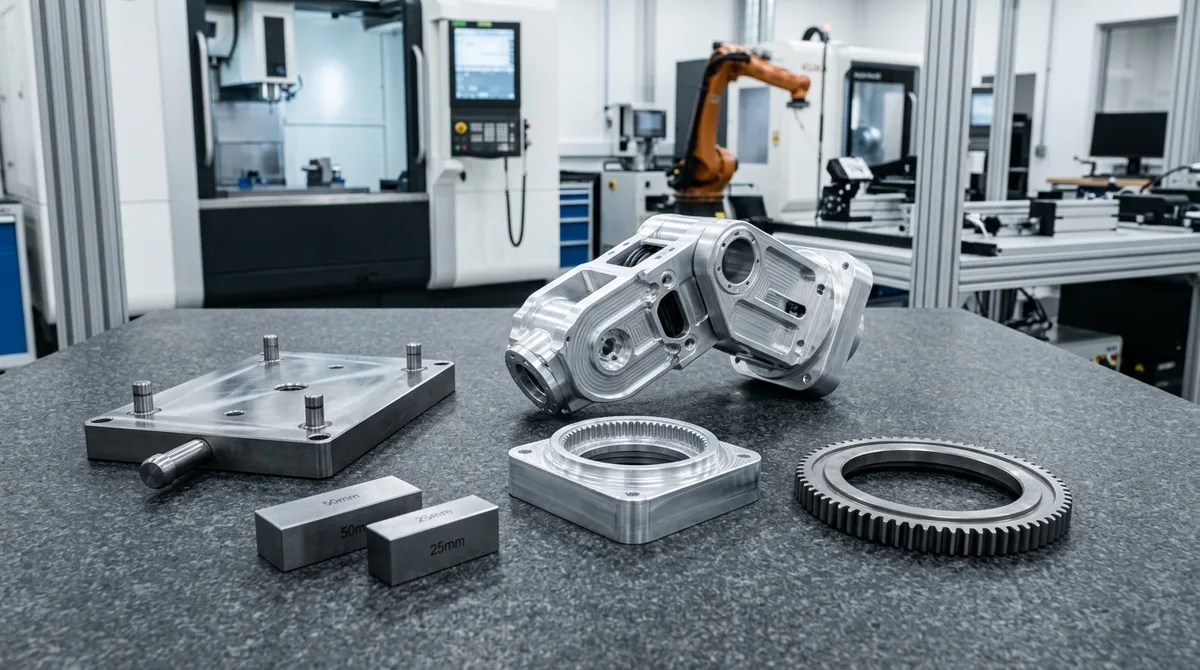
Figure 1: High-precision 7075-T6 robotic actuator housing resting flat on a granite inspection table alongside precision gauge blocks, machined in an automated smart CNC cell utilizing zero-point palletization and in-process probing.
Closed-Loop In-Process Probing and Dynamic Tool Wear Compensation
One of the most consequential advancements in smart prototype manufacturing is the integration of on-machine touch trigger probes (OMP) operating over optical or radio frequencies. Instead of transferring a semi-finished prototype to an offline coordinate measuring machine (CMM) to inspect critical bore diameters, the CNC spindle automatically indexes a kinematic ruby stylus probe from the tool carousel to inspect datums directly within the machining envelope.
During unattended machining cycles, cutting edge friction and abrasive thermal wear gradually erode carbide end mills and ball nose cutters. In conventional operations, this tool wear manifests as dimensional drift: internal bore diameters contract, external boss widths expand, and thin wall ribs accumulate taper. In a smart CNC cell, closed-loop probing routines measure critical test features immediately following semi-finishing passes.
The measured physical dimension is compared against the nominal CAD geometry programmed in the machine coordinate system. The deviation vector is calculated dynamically:
ΔRwear = (ΔD / 2) × cos(αprobe)
Where:
- ΔD: Measured diametrical error on internal bore or external cylindrical boss (mm).
- ΔRwear: Incremental tool radius offset adjustment written directly to the CNC tool geometry register (mm).
- αprobe: Vector contact angle between the ruby stylus travel trajectory and the normal surface tangent (degrees).
If the measured bore is undersized by 0.012 mm due to flank wear on the finishing end mill, the macro script automatically updates Tool Offset Register #14 by -0.006 mm and executes a spring pass finish cut. This closed-loop compensation loop guarantees that the finished feature satisfies strict engineering drawing callouts of ±0.010 mm without requiring manual intervention from a quality technician.
Thermal Drift Mitigation in Automated Prototyping Environments
While structural rigidity and tool wear dominate short-cycle machining, thermal expansion constitutes the largest source of volumetric error in extended prototype runs. High-speed spindle rotation at 15,000 to 24,000 RPM generates substantial friction heat across ceramic hybrid bearings, while ball screw drive friction and hydraulic power units warm the machine casting.
The linear thermal growth of a metal component or machine axis follows the fundamental thermodynamic relationship:
In this equation:
- ΔL: Total dimensional thermal expansion or contraction along the measurement axis (mm).
- L0: Nominal feature length or machine axis displacement length at standard calibration temperature (mm).
- αΔT: Linear coefficient of thermal expansion (CTE) of the material (K-1). For 6061-T6 aluminum, α = 23.6 × 10⁻⁶ K-1; for 7075-T651, α = 23.4 × 10⁻⁶ K-1; for 316L stainless steel, α = 16.0 × 10⁻⁶ K-1; and for Ti-6Al-4V Grade 5 titanium, α = 8.6 × 10⁻⁶ K-1.
- (Tcurrent – Tref): Temperature differential between the current machine/workpiece state and standard metrology reference temperature (20.0°C / 68.0°F).
Consider a precision aerospace optical chassis machined from 6061-T6 aluminum with an overall mounting span of L0 = 300 mm. If the CNC machining enclosure rises from 20.0°C to 26.5°C during a prolonged 4-hour roughing and finishing cycle, the uncompensated thermal growth of the workpiece evaluates to:
An error of 46 μm is more than four times the allowable tolerance of a ±0.010 mm bore pattern. If machined under elevated enclosure temperatures and inspected later in a climate-controlled 20°C metrology lab, the hole center-to-center distances will contract significantly, resulting in non-conformance.
Smart prototype manufacturing mitigates this thermodynamic error through three synchronized controls:
- Spindle Chillers and Direct-Drive Core Cooling: Refrigerated closed-loop coolant circulates through spindle jackets and hollow ball screws, maintaining internal casting temperatures within ±0.5°C of ambient.
- Multi-Point Thermistor Feedback: High-precision thermistors mounted across the spindle nose, X/Y/Z casting beds, and coolant delivery nozzles feed live temperature deltas into the CNC controller. The controller executes real-time polynomial thermal compensation algorithms that dynamically shift machine axis zero points.
- Workpiece Thermal Soaking Protocol: Prior to final CMM inspection or critical on-machine finishing passes, parts undergo controlled temperature stabilization in a 20.0°C ± 0.5°C climate-controlled metrology environment, preventing post-machining shrinkage errors.
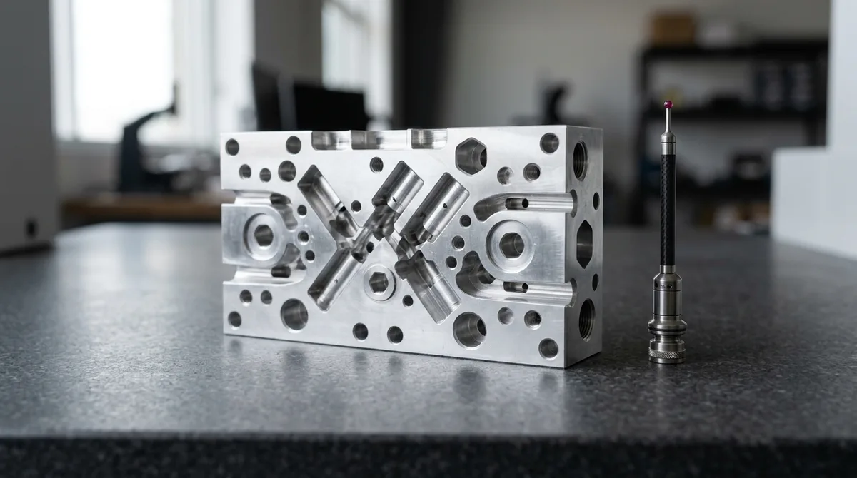
Figure 2: Precision 5-axis CNC machined aerospace hydraulic manifold resting flat on a Grade 00 granite surface plate beside a carbon-fiber shaft ruby stylus CMM probe, representing the metrology validation tier in smart prototype manufacturing.
Industrial IoT Architecture: OPC-UA, MTConnect, and Digital Twin Simulation
The digital backbone connecting disparate CNC machine tools, automated storage carousels, and coordinate measuring machines is standard industrial telemetry. Historically, legacy machine tools operated proprietary protocols that locked operational data inside closed CNC architectures. Smart prototype manufacturing adopts open protocols—predominantly OPC-UA (Open Platform Communications Unified Architecture) and MTConnect.
Through edge gateways wired directly to machine controllers (such as Fanuc FOCAS, Siemens Sinumerik Operate, and Heidenhain RemoTools), the production engineering team extracts standardized XML/JSON data packets at 10 Hz to 100 Hz frequencies. The primary monitored telemetry channels include:
- Spindle Load and Torque Percentage: Real-time torque monitoring identifies micro-fractures in ceramic or carbide inserts during roughing passes on Inconel 718 or 17-4PH stainless steel before catastrophic tool failure damages the raw billet.
- Axis Velocity and Feed Rate Override: Tracking intentional operator overrides highlights CAM programming inefficiencies or unoptimized chip-thinning feed calculations.
- Acoustic Emission and Tri-Axial Accelerometers: Spindle vibration sensors identify chatter onset frequencies, allowing the controller to dynamically modulate spindle RPM into stable harmonic cutting zones.
- Coolant Concentration and Pressure Transducers: Maintaining water-soluble coolant refractometer brix levels between 8% and 10% and high-pressure through-spindle coolant (70 bar / 1,000 PSI) prevents chip recutting during deep-cavity pocketing.
Simultaneously, Digital Twin kinematics are executed prior to machine setup. Using G-code verification platforms like VERICUT and integrated NX CAM machine simulation, engineers render a virtual twin of the exact 3-axis, 4-axis, or 5-axis CNC machine, complete with physical kinematics, stroke limits, tool holders, and zero-point pallet chucks. The simulation processes the identical ISO G-code that executes on the factory floor, catching tool holder gouges, rapid traverse table collisions, and axis over-travel limit faults before a single cutting tool engages raw metal.
Shop-Floor Equipment Reality: 3-Axis & 4-Axis VMCs vs. 5-Axis Strategic Allocation
In international industrial marketing, rapid prototyping services frequently emphasize 5-axis simultaneous CNC machining as a universal panacea. However, transparent precision manufacturing demands a realistic assessment of shop-floor machine utilization and capital efficiency.
In an optimized smart manufacturing shop floor, high-speed 3-axis and 4-axis vertical machining centers (VMCs) execute between 75% and 85% of total machining hours. Structural enclosures, electronic heat sinks, sheet metal forming dies, mounting brackets, and face plates possess predominantly prismatic geometric topologies. Machining these prismatic components on a 3-axis VMC equipped with a high-torque 15,000 RPM spindle and rigid pneumatic Kurt vises delivers superior cutting stiffness, faster volumetric metal removal rates (MRR), and substantially lower machine hour costs compared to complex multi-axis machines.
When multi-side access is required, smart facilities mount 4th-axis rotary indexers (A-axis or B-axis) or multi-pallet tombstones onto horizontal machining centers. This enables complete 4-sided prismatic machining in a single automated fixture clamping, locking positional runout between perpendicular faces to within ±0.008 mm.
In contrast, simultaneous 5-axis machining centers (utilizing trunnion table A/C or swivel head B/C kinematics) are strategically deployed for geometries where 3-axis access is geometrically impossible:
- Aerospace Blisks and Impellers: Twisted aerodynamic airfoils with undercuts and zero tool shank clearance that require continuous vector orientation of the cutter axis.
- Complex Hydraulic Manifolds: Cross-drilled port blocks where hydraulic fluid galleries intersect at compound angles, requiring 5-axis directional deep hole drilling with minimum tool projection length to prevent hole wandering.
- Orthopedic Medical Implants: Polyaxial bone plates and femoral knee components featuring organic, sculptured NURBS surfaces requiring ball end mill scallop height control below 0.8 μm Ra without manual polishing.
Over-specifying a simple enclosure or mounting plate as “5-axis machined” inflates machining hour rates by 200% to 300% without improving functional tolerances. Smart prototyping engineering evaluates the native CAD topology during the automated DFM review, routing prismatic surfaces to high-efficiency 3-axis/4-axis cells and reserving 5-axis centers exclusively for complex topological challenges.
Engineering Benchmark Tables
The following technical tables contrast traditional rapid prototyping operations with Industry 4.0 smart manufacturing cells, detailing key operational, metrological, and hardware parameters across high-mix precision workflows.
| Performance Metric | Traditional Machine Shop | Smart Prototyping Cell (Industry 4.0) | Engineering Mechanism & Impact |
|---|---|---|---|
| Setup & Changeover Time | 45 to 120 minutes per setup | Under 3 minutes per pallet change | Pneumatic zero-point clamping receivers decouple offline fixturing from spindle run time. |
| Spindle In-Cut Utilization | 32% to 45% of shift time | 78% to 88% continuous duty | Automated pallet changers (APC) and standardized tooling libraries eliminate operator waiting. |
| First-Article Inspection (FAI) | Part unclamped, taken to CMM lab (2-4 hr lag) | In-situ spindle probing in 60 to 90 seconds | Optical touch trigger probes measure critical bores and surfaces without losing workpiece WCS origin. |
| Tool Wear Compensation | Manual caliper/micrometer entry by operator | Automated closed-loop CNC register update | Deviation algorithm calculates delta and writes directly to tool geometry offset table. |
| Dimensional Repeatability | ±0.025 mm to ±0.050 mm | ±0.005 mm to ±0.010 mm | Thermal casting chillers, glass scale feedback (< 0.1 μm resolution), and standardized clamping. |
| Ex-Factory Turnaround | 12 to 20 business days | 4 to 8 business days (prototypes) | Compressed queue times, rapid DFM response within 24h, and lights-out night shift execution. |
| Subsystem Category | Core Hardware & Tooling | Communication & Interface | Controlled Tolerance Metric | Primary Failure Mode Mitigated |
|---|---|---|---|---|
| Kinematic Fixturing | Pneumatic zero-point chucks, pull studs, ground pallets | Mechanical ball-lock with air seating confirm | Repeatability < 0.002 mm | Operator vise-jaw misalignment and torque inconsistency. |
| On-Machine Metrology | Optical/radio touch probes, ruby styli (ø2-6 mm) | High-speed optical infrared / 2.4 GHz radio | Unidirectional repeatability < 1.0 μm | Workpiece WCS zero shift during multi-setup machining. |
| Tool Condition Telemetry | Non-contact laser tool setters, breakage beams | Hardwired digital I/O to CNC controller | Length/radius check ±0.001 mm | Broken tap/drill running into subsequent features causing part scrap. |
| Shop Telemetry (IIoT) | Industrial edge PCs, tri-axial vibration sensors | OPC-UA, MTConnect over Ethernet IP | Sample rate 100 Hz (load, RPM, temp) | Undetected spindle bearing degradation and harmonic chatter. |
| Offline Metrology Tier | Bridge CMM with scanning probe head, granite plate | Direct CAD file import (STEP/IGES) | Volumetric error E0 ≤ 1.5 + L/350 μm | Complex GD&T true position and profile tolerance non-conformance. |
Failure Mode and Effects Analysis (FMEA) for Smart Machining Cells
Deploying automated and lights-out machining cells introduces unique shop-floor engineering challenges. Without an operator continuously observing the cutting envelope, automated safety mechanisms and rigorous failure prevention protocols are essential to protect expensive machine spindles and preserve tight-tolerance billets.
1. Chip Contamination on Zero-Point Pallet Cones
Failure Mechanism: During pallet exchange, microscopic aluminum or steel chips (as small as 15 μm) falling onto the conical mating taper can tilt the pallet. This generates an angular runout error of 0.015 mm to 0.030 mm across a 200 mm part face, causing planar parallelism non-conformance.
Mitigation Protocol: Smart receiver chucks incorporate automated pneumatic seating validation. High-pressure filtered air (6 bar) continuously purges the conical locating surfaces throughout the unclamping and indexing cycle. When the new pallet locks down, back-pressure pneumatic sensors measure air leakage around the seating face. If back pressure deviates from calibrated thresholds—indicating a trapped particle—the CNC pauses execution and signals an automated clean cycle before engaging cutting tools.
2. Dynamic Ruby Stylus Cosine Error & Shorter Calibration Intervals
Failure Mechanism: When an on-machine touch probe measures angled side walls or curved fillets, the contact point between the spherical ruby stylus and the metal surface is offset from the probe’s axial center of motion. If the CNC macro calculates coordinates assuming planar contact, a geometric cosine error is introduced:
Mitigation Protocol: Machine inspection macros utilize calibrated stylus vectors mapped across a calibrated ceramic reference sphere mounted inside the machine envelope. Before running high-precision inspection routines, the probe touches the reference sphere from multiple radial vectors, automatically logging ruby deflection pre-travel offsets into system variables to cancel out cosine errors.
3. Workpiece Clamping Stress and High-Speed Roughing Distortion
Failure Mechanism: Billet stock of 7075-T651 or 6061-T6 retains residual internal stresses from rolling and heat treatment quenching. When aggressive high-speed machining (HSM) removes 70% to 80% of the raw material envelope, the redistribution of residual stresses causes the part to bow, twist, or cup once unclamped from the pallet.
Mitigation Protocol: Smart prototype programming follows a strict three-stage protocol:
- Stage 1 (Roughing & Stress Relief): Rough out the component leaving 0.8 mm stock on all critical surfaces. Unclamp the pallet pull studs to release mechanical clamping tension, allowing the bulk material to flex and reach internal equilibrium.
- Stage 2 (In-Situ Re-Probing): Re-clamp the pallet with reduced hydraulic/pneumatic pressure and re-probe primary datums with the optical spindle probe to establish the relaxed part coordinate system.
- Stage 3 (Semi-Finishing and Finishing): Execute high-speed finishing passes with sharp carbide tools, maintaining low cutting temperatures and balanced radial tool engagement.
Frequently Asked Questions (FAQ)
Traditional rapid prototyping relies heavily on manual operator setups, disconnected CMM inspections, and subjective tool wear compensation, leading to longer lead times and higher variability across batches. Smart prototype manufacturing integrates Industry 4.0 automation: standardized zero-point palletization (repeatability under 0.002 mm), on-machine optical probing for real-time tool offset compensation, and digital twin simulation. This enables tight tolerances of ±0.010 mm and compresses ex-factory prototyping delivery to 4 to 8 business days.
Yes. By utilizing climate-controlled machine enclosures, active spindle and ball-screw chiller systems, linear glass optical scales with sub-micron resolution, and automated closed-loop probing that dynamically updates CNC tool wear registers, smart machining cells reliably hold tolerances of ±0.010 mm on critical bore diameters and milling profiles.
In traditional workflows, verifying a semi-finished prototype requires stopping the machine, unclamping the part, transporting it to a temperature-controlled CMM metrology lab, and waiting hours for inspection results. Closed-loop spindle probing measures datums and critical features directly inside the machining envelope in under 90 seconds, automatically applying tool wear offsets and executing finishing passes without losing workpiece coordinate alignment.
High-speed 3-axis and 4-axis vertical machining centers (VMCs) handle 75% to 85%+ of prototype manufacturing capacity for structural enclosures, electronic housings, and mounting brackets. They provide superior stiffness, higher material removal rates, and lower machine-hour costs. Simultaneous 5-axis machining is strategically reserved for geometries with complex compound contours, aerodynamic impellers, and angled hydraulic manifold cross-bores.
Direct 3D CAD files formatted in STEP (.stp), IGES (.igs), or Parasolid (.x_t) are required for automated CAM programming and digital twin simulation. For parts with tight tolerance callouts (tighter than ISO 2768-mK), thread specifications, or specific surface finishes, a complementary 2D engineering drawing in PDF format with fully defined GD&T datums must accompany the 3D geometry.
Accelerate Your Product Development with Smart Prototype Manufacturing
Upload your 3D CAD files today for automated DFM analysis, comprehensive GD&T review, and high-precision CNC machining.
Submit CAD Models for Instant DFM & Quote