The continuous global expansion of 5G infrastructure and high-frequency millimeter-wave (mmWave) telecommunications has fundamentally transformed mechanical and thermal hardware specifications. Unlike legacy 4G LTE cellular equipment, modern 5G architectures operate across higher frequency bands (ranging from Sub-6 GHz up to 39 GHz mmWave). While these frequencies unlock unprecedented multi-gigabit data transfer rates, ultra-low latency, and massive machine-type communication, they introduce severe physical limitations: drastic free-space path loss, severe electromagnetic interference (EMI), and immense localized thermal power densities.
To overcome these harsh RF physics, telecom hardware engineers and IoT enclosure designers can no longer depend on conventional sheet metal stampings, standard die-cast zinc boxes, or molded plastics. Instead, precision multi-axis CNC machining, high-tolerance sheet metal fabrication, and submerged slow-wire Electrical Discharge Machining (EDM) have become the indispensable manufacturing cornerstones driving modern 5G base station active antenna units (AAUs), remote radio heads (RRHs), small cell transceivers, and edge computing servers. At AS Prototypes, our precision CNC machining services and dedicated custom sheet metal fabrication shop deliver turnkey mechanical solutions engineered specifically for high-frequency microwave reliability.
Executive Summary & Engineering Takeaways (BLUF)
- Core Focus & DFM Scope: Actionable shop-floor engineering guidelines for precision machining for 5g telecom, covering material selection, geometric tolerancing, and defect prevention.
- Cutting & Forming Precision: Fiber laser and abrasive waterjet profiles hold ±0.05 to ±0.10 mm (±0.002″ to ±0.004″); CNC press brake flanges hold ±0.15 mm (±0.006″) and ±0.5° angular accuracy per DIN 6935.
- Edge Quality & Material Gauge: Burr-free nitrogen-assisted laser edges across 0.5 mm to 12.0 mm standard sheet metal stock (5052-H32, SPCC/SECC, SPHC, 304/316L, T2 Copper) and zero-HAZ cold waterjet kerfs up to 50 mm plate.
- K-Factor & Flat-Pattern DFM: Empirical bend deduction calibration (K = 0.33–0.44) with grain-direction stress relief to prevent flange cracking and springback drift.
- Ex-Factory Turnaround: 4 to 8 business days for laser/waterjet cut and bent sheet metal prototypes; 7 to 12 business days with powder coating, anodizing, or PEM hardware insertion (excluding 3–5 days air transit).
Article Engineering Navigation
- 1. Thermal Management & Electromagnetic Compatibility: Overcoming mmWave Physics
- 2. Microwave Cavity Filters & Waveguides: Micron-Level Geometries and Wire EDM
- 3. Comprehensive Engineering Specifications for 5G Telecom Subsystems
- 4. Precision Sheet Metal Fabrication for 5G Cabinets, Racks & Outdoor Enclosures
- 5. Environmental Defense & Surface Finishing for 10-to-15 Year Outdoor Reliability
- 6. In-House Metrology & Quality Assurance Protocols
- 7. Accelerate Your 5G Telecom Hardware Development with AS Prototypes
- 8. Technical Engineering FAQ
1. Thermal Management & Electromagnetic Compatibility: Overcoming mmWave Physics
Every evolutionary step in wireless carrier frequencies demands significantly greater digital signal processing capability and higher radio frequency (RF) output amplification. A typical 5G Massive MIMO (Multiple-Input Multiple-Output) active antenna array integrates 64 transmitter and 64 receiver (64T64R) channels within a single chassis, dissipating between 800 W and 1,500 W of concentrated thermal waste. This thermal flux—often exceeding 15 to 25 W/cm² across concentrated gallium nitride (GaN) power amplifier dies and baseband ASICs—causes severe thermal throttling and catastrophic signal degradation if heat is not evacuated immediately.
Concurrently, high-frequency mmWave transmissions suffer from minimal skin depth and severe vulnerability to cross-talk between adjacent RF pathways. Monolithic aluminum enclosures machined from solid wrought billets solve both challenges simultaneously:
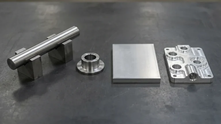
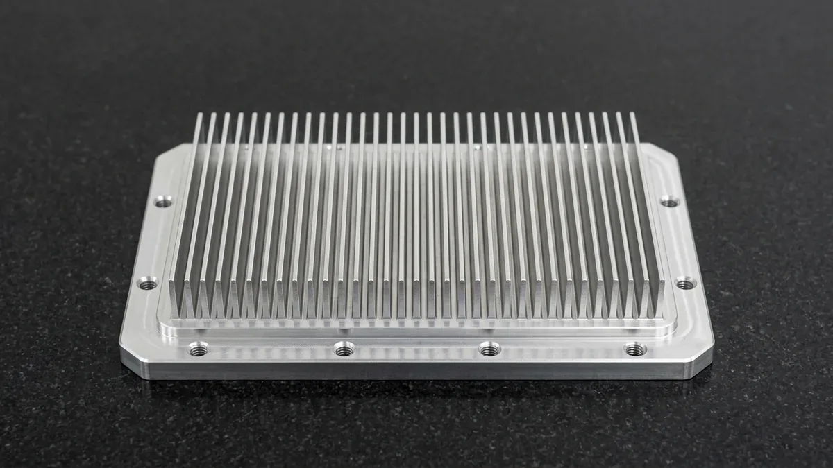
- Monolithic Thin-Fin Thermal Architecture: Utilizing high-speed 3-axis and 5-axis CNC milling centers, our machinists cut high-aspect-ratio cooling fin arrays directly from structural aluminum billets (6063-T5 or 6061-T6). Achieving fin thicknesses down to 0.8 mm with aspect ratios exceeding 12:1 directly into the chassis eliminates thermal interface joint resistance, maximizing passive convection and forced-air heat dissipation.
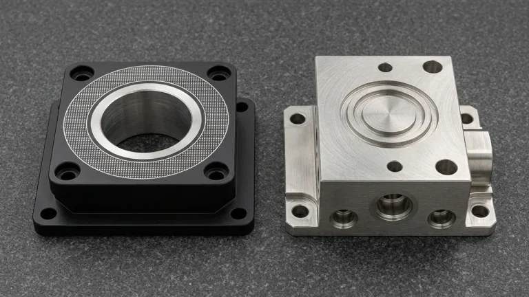
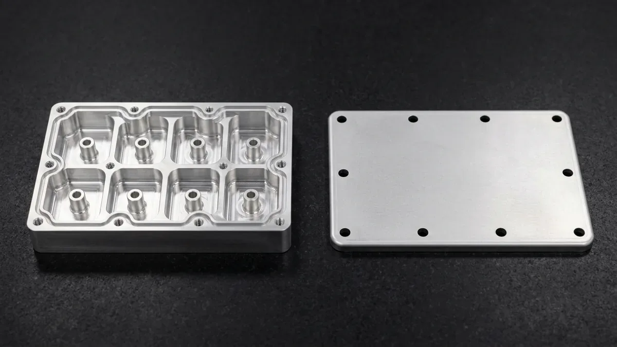
- Airtight Multi-Chamber RF Shielding: Internal filter compartments are milled with continuous O-ring and conductive elastomeric gasket channels held to tight ±0.015 mm dimensional tolerances, preventing electromagnetic radiation leakage and preserving channel isolation exceeding 80 dB at 28 GHz.
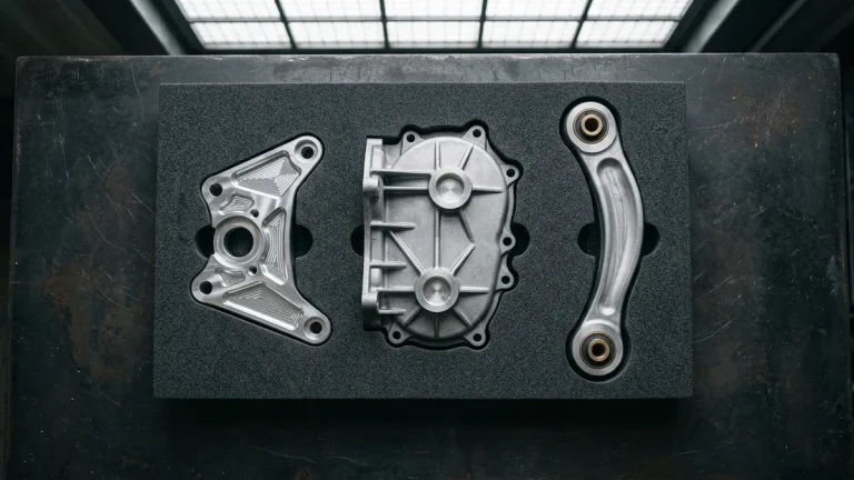
- Long-Term Structural Stability: Unlike die-cast parts prone to internal porosity, wrought aerospace alloys exhibit isotropic mechanical density, withstanding decades of outdoor wind loading, freeze-thaw thermal cycles, and seismic vibration without micro-fracturing or seal relaxation.
2. Microwave Cavity Filters & Waveguides: Micron-Level Geometries and Wire EDM
In 5G RF front-end architectures, cavity bandpass filters and duplexers are responsible for rejecting out-of-band noise while allowing target carrier frequencies to pass with minimal insertion loss (< 0.15 dB). Preserving a high resonator quality factor (Q-factor) requires rigorous geometrical precision and pristine surface morphology:
- Resonant Cavity Tolerances: Resonator post heights, wall thicknesses, and pocket depths govern resonant frequencies. Dimensional variations as small as 10 μm cause substantial frequency drift, requiring costly manual tuning screws. Our high-speed milling processes hold critical cavity features to ±0.010 mm to ±0.015 mm.
- Submerged Wire EDM Micro-Geometry: While CNC end mills leave a corner radius equal to the cutter radius, rectangular waveguide apertures and coupling iris windows require razor-sharp internal corners. We utilize submerged slow-wire EDM with 0.20 mm brass wire to cut intricate aperture geometries with internal corner radii as tight as R0.10 mm.
- Low-Roughness RF Surface Finish (Ra ≤ 0.4 μm): Due to the RF skin effect at 28 GHz to 39 GHz, electrical current travels exclusively within the outer 0.4 to 0.6 μm of the metal surface. Any microscopic machining ridges increase effective electrical path length and elevate attenuation. We optimize toolpath stepovers, spindle speeds (up to 24,000 RPM), and light diamond-burnishing passes to deliver surface finishes of Ra ≤ 0.4 μm per ISO 4287.
3. Comprehensive Engineering Specifications for 5G Telecom Subsystems
Selecting appropriate materials, manufacturing processes, and mechanical tolerances is essential when engineering high-frequency telecom assemblies. The following comparative engineering matrix outlines baseline manufacturing specifications for primary 5G subsystems:
| 5G Subsystem Component | Primary Material | Manufacturing Process | Critical Tolerance | Surface Finish & RF Spec |
|---|---|---|---|---|
| mmWave Cavity Filter | 6061-T6 / C3604 Brass | High-Speed 3/4-Axis VMC Milling + Wire EDM | ±0.010 mm | Silver Plating / >80 dB @ 28 GHz |
| Massive MIMO Heatsink | 6063-T5 / Pure Copper C11000 | High-Speed 3-Axis Thin-Fin CNC Profiling | ±0.050 mm | Conductive Chemical Film / 200 W/(m·K) |
| Outdoor Base Station Cabinet | 5052-H32 / Galvanized Steel SECC | Fiber Laser Cutting & CNC Bending | ±0.150 mm | UV Powder Coat / IP67 Sealing |
| Precision Waveguide Flange | OFHC Copper C10100 / Brass | Micro-CNC Turning & Slow-Wire EDM | ±0.005 mm (Wire EDM) | Gold Flash / Insertion Loss < 0.15 dB |
| Liquid Cold Plate Manifold | 6061-T6 Aluminum | Deep Cavity 3/4-Axis Milling & Vacuum Brazing | ±0.020 mm | Anodized / Pressure Decay Leak Tested (3.5–6.0 bar) |
4. Precision Sheet Metal Fabrication for 5G Cabinets, Racks & Outdoor Enclosures
While massive MIMO heatsinks and microwave cavity filters demand monolithic CNC machining, larger telecom chassis, edge server racks, and tower-mounted battery enclosures rely heavily on custom sheet metal fabrication. Fabricating rugged outdoor telecom housings requires strict adhesion to mechanical Design for Manufacturability (DFM) principles:
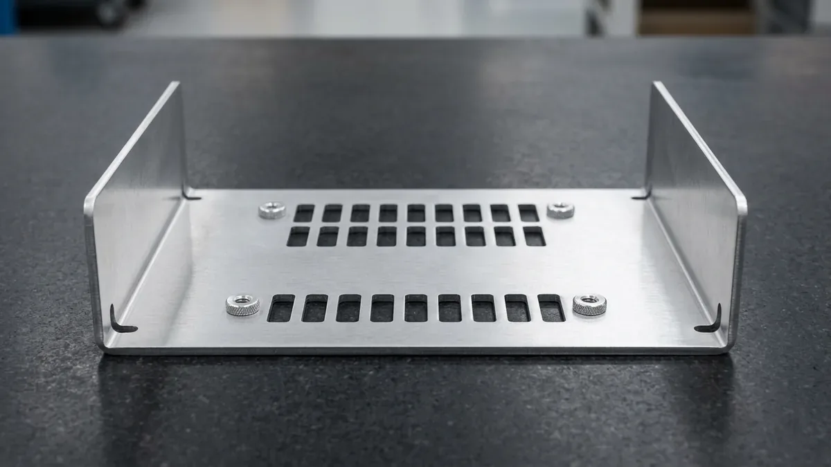
- Fiber Laser Blanking: Sheet aluminum (5052-H32) and corrosion-resistant electro-galvanized cold-rolled steel are cut using high-power fiber lasers equipped with nitrogen assist gas, producing clean, burr-free edges and intricate ventilation perforation patterns without thermal distortion.
- CNC Press Brake Bending: Multi-axis CNC press brakes execute complex progressive bend sequences. Because hard 6061-T6 sheet cracks along the outer tension radius when bent tightly (R < 3t–6t), we specify ductile 5052-H32 aluminum for bent telecom chassis, enforcing minimum inside bend radii (R ≥ 1.0t, where R is inside radius and t is material thickness) and positioning louvers and venting slots at least 3t away from primary bend tangent lines.
- Automated Fastener Insertion: To withstand ongoing mechanical vibration from wind shear and cooling fans, threaded connections are established using self-clinching PEM hardware (studs, standoffs, and captive nuts). Calibrated hydraulic insertion embeds fasteners with controlled tonnage, ensuring superior push-out and torque-out resistance without distorting adjacent sheet metal panels.
- Environmental Ingress Protection (IP65 / IP67): Enclosure doors and access panels incorporate formed labyrinth seal flanges, polyurethane foam-in-place (FIPFG) gaskets, and precision conductive elastomeric strips to guarantee watertight integrity against driving rain, blowing dust, and condensation.
5. Environmental Defense & Surface Finishing for 10-to-15 Year Outdoor Reliability
5G remote radio heads and tower-mounted antennas are deployed outdoors in extreme climatic zones, enduring relentless ultraviolet (UV) radiation, desert temperature fluctuations (-40°C to +85°C), and corrosive maritime salt spray. At AS Prototypes, our comprehensive surface finishing capabilities combine complementary protective treatments:
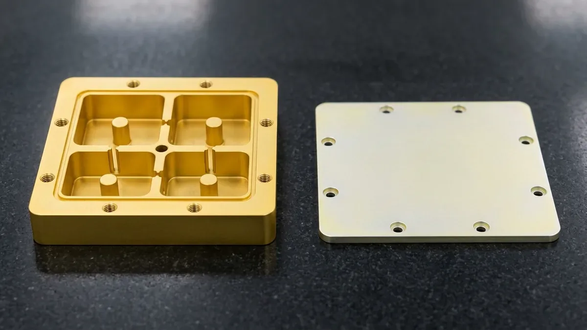
- Conductive Chemical Conversion (Alodine / SurTec 650): Internal RF cavity pockets, grounding pads, and mating flanges receive MIL-DTL-5541 Type I or Type II chemical conversion coatings. This thin chromate conversion film passivates aluminum against oxidation while maintaining ultra-low electrical contact resistance (< 5 mΩ) critical for RF grounding and EMI gasket conductivity.
- MIL-A-8625 Type III Hardcoat Anodizing: For extreme wear resistance on external structural frames, hardcoat anodizing produces a dense, ceramic-hard aluminum oxide layer (40 to 50 μm thickness) with micro-hardness exceeding 450 to 550 HV0.05, impervious to scratch damage and chemical attack.
- Architectural UV-Resistant Powder Coating: Exterior sheet metal cabinets and sunshields are electrostatic powder-coated using architectural polyester resins (in standard telecom light grey RAL 7035). This thick, resilient coating provides superior barrier protection against solar chalking, acid precipitation, and mechanical impact, validated by salt spray testing exceeding 1,000 hours.
6. In-House Metrology & Quality Assurance Protocols
Delivering microwave mechanical components that assemble seamlessly into active telecom arrays mandates closed-loop quality verification. In our temperature-controlled inspection laboratory, mechanical engineers verify part compliance against your 2D engineering drawings and GD&T specifications:
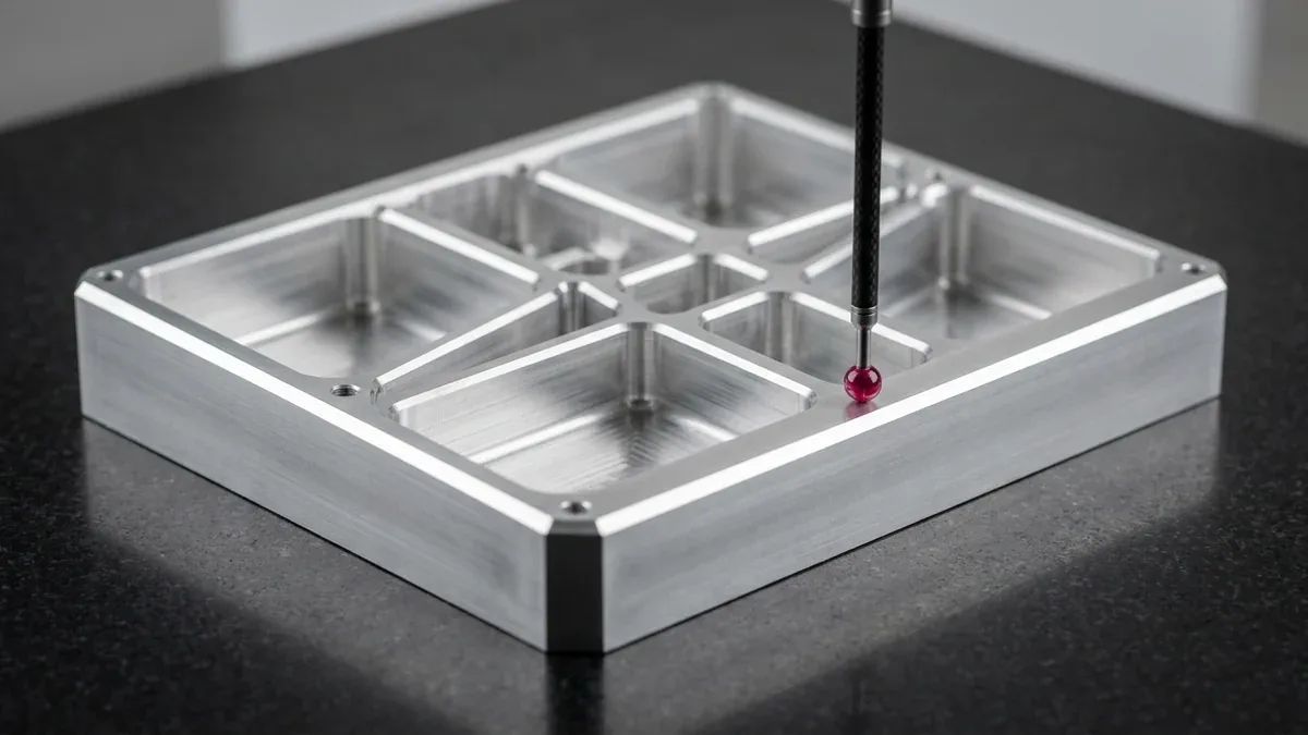
- Mating Assembly Fit-Up & Cavity Metrology: For sheet metal rack sub-chassis and EMI shielding lids, our quality team performs 100% mating housing-to-cover fit-up checks, 90° squareness gauging, and Go/No-Go thread plug verification; for rigid CNC-milled RF cavity filter blocks, multi-axis bridge coordinate measuring machines verify resonant pocket depths and port parallelism.
- 2.5D Optical Video Metrology: High-resolution optical comparators verify delicate waveguide dimensions, thin-fin spacing, and burr-free edge radii without physical contact deflection.
- Conductive Gasket Compression Testing: Milled O-ring grooves are inspected for depth and surface finish uniformity to ensure proper 20% to 30% elastomeric gasket compression upon final enclosure torquing.
- Comprehensive Quality Documentation: Full First Article Inspection (FAI) reports, dimensional sampling data, and raw material mill test reports (MTR) are provided on demand with every production batch.
7. Accelerate Your 5G Telecom Hardware Development with AS Prototypes
From initial rapid prototyping of massive MIMO antenna heatsinks to low-to-medium volume manufacturing of weatherized edge computing enclosures, AS Prototypes provides complete engineering support. Our Shenzhen manufacturing facility brings together:
- High-Speed Multi-Axis Machining: Precision 3-axis, 4-axis, and simultaneous 5-axis CNC machining centers holding tight ±0.010 mm tolerances on complex aluminum microwave cavities.
- Integrated Sheet Metal Shop: Advanced fiber laser cutting, precision CNC press brakes, automated PEM hardware insertion, and robotic TIG/MIG welding.
- Micro-EDM Precision: Submerged slow-wire EDM and sinker EDM for intricate waveguide resonators, narrow slits, and deep internal ribs.
- Rapid Production Turnaround: Standard prototype parts machined and delivered within 4 to 8 business days, finished and assembled components within 7 to 12 business days, and comprehensive DFM feedback with formal quotations provided within 24 hours.
🔗 Related Sheet Metal & Secondary CNC Fabrication Guides:
When specifying precision machining for 5G telecom for structural chassis and enclosures, controlling bend springback, edge burr condition, and protective coatings prevents assembly interference. Consult our Precision Sheet Metal Forming: 7 Engineering Best Practices, review Progressive Stamping Die & Forming DFM Rules, and compare corrosion protection in our Complete Metal Surface Finishing Guide.
8. Technical Engineering FAQ
We routinely hold ±0.010 mm to ±0.015 mm tolerances on critical internal RF resonant cavity dimensions, resonator post heights, waveguide apertures, and conductive gasket sealing grooves utilizing high-speed 3-axis and 4-axis CNC milling centers (with simultaneous 5-axis available for compound-angle ports) and submerged slow-wire EDM.
We recommend a dual-finish specification: MIL-DTL-5541 conductive chemical conversion coating (Alodine / SurTec 650) on interior RF cavities to preserve electrical conductivity and RF grounding, paired with architectural UV-resistant powder coating or MIL-A-8625 Type III Hardcoat Anodizing on exterior surfaces to endure 10+ year outdoor weather exposure.
For high-aspect-ratio heatsink fins (down to 0.8 mm thickness with 12:1 height-to-gap ratios), our CAM programmers employ dynamic high-feed milling strategies, step-down roughing with constant tool engagement, vibration-dampening workholding fixtures, and high-pressure mist coolant to prevent chatter and dimensional distortion.
Rapid CNC machined and sheet metal prototypes are completed within 4 to 8 business days. Parts requiring secondary treatments like chromate conversion, anodizing, or powder coating are delivered in 7 to 12 business days, with quotes and DFM feedback returned within 24 hours.
Engineer Precision Custom Sheet Metal Enclosures & Brackets
Eliminate bend springback, hole distortion, and assembly interference before cutting metal. Upload your 3D CAD files (STEP/IGES) and 2D flat-pattern drawings for a dedicated sheet metal DFM review and custom production quotation.
Upload CAD Files for Sheet Metal DFM & Quote