In precision mechanical engineering, specifying nominal dimensions and geometric tolerances (GD&T) defines only part of a component’s functional reality. The microscopic boundary topography of a machined part—governed by international surface texture and roughness standards—fundamentally dictates dynamic tribological friction, boundary lubrication retention, fluid dynamic drag, and seal hermeticity.
In our Shenzhen machine shop, achieving predictable surface integrity requires strict metrological alignment across design engineering, CAM toolpath programming, and shop-floor quality inspection.
Yet, surface texture remains one of the most widely misunderstood disciplines in mechanical design. Misinterpreting the critical distinction between Roughness (Ra vs. Rz), Waviness (Wa/Wt), and Machining Lay frequently leads to premature mechanical wear, seized bearing journals, or needlessly inflated cycle times.
Furthermore, for injection-molded parts, die-cast housings, and CNC prototypes, specifying industrial texturing standards—such as VDI 3400 spark erosion via electrical discharge machining (EDM) or Mold-Tech chemical etching—requires precise draft angle compensation to prevent severe demolding scuff marks.
This comprehensive engineering guide examines surface texture metrology per ASME B46.1, ISO 4287, and ISO 21920, details shop-floor texturing technologies, and provides actionable DFM rules for precision prototypes and production components.
Executive Summary & Engineering Takeaways (BLUF)
- Standard Machined Baseline: Standard high-speed CNC milling achieves Ra 1.6 to 3.2 µm (63 to 125 µin); fine finishing passes yield Ra 0.8 µm (32 µin), while wiper face mills achieve Ra 0.4 µm (16 µin).
- Ra vs. Rz Conversion: For milled surfaces, Rz ≈ 4 × Ra to 7 × Ra; for ground surfaces, Rz ≈ 3 × Ra to 5 × Ra. High-pressure dynamic seals require controlling Rz to eliminate localized leakage paths.
- Textured Mold Draft Rule: Add a minimum of 1.0° to 1.5° of positive draft angle per 0.025 mm (0.001″) of texture depth beyond standard 1.0° baseline draft.
- Metrology Verification: Tactile skidless diamond stylus profilometers (r = 2 µm per ISO 3274 / ISO 4287) and 2.5D optical vision systems calibrated against traceable master roughness specimens.
- Turnaround Expectation: 4 to 8 business days for precision CNC prototypes; 7 to 12 business days for bead-blasted and anodized production batches.
Article Engineering Navigation
- 1. The Anatomy of Surface Texture: Roughness, Waviness & Lay
- 2. Deciphering Surface Roughness Metrics: Ra vs. Rz vs. 3D Areal Parameters
- 3. Shop-Floor Kinematic Calculation: Theoretical Roughness vs. Wiper Inserts
- 4. Mechanical & Chemical Industrial Texturing Technologies
- 5. Draft Angle Engineering for Textured Mold Tooling
- 6. Comprehensive Engineering Matrix: Texture Specifications & Applications
- 7. Engineering Drawing Callout Standards & Metrology Verification
- 8. Shop-Floor Surface Texture Troubleshooting: Root Causes & Corrective Actions
- 9. Technical Engineering FAQ
1. The Anatomy of Surface Texture: Roughness, Waviness & Lay
Surface texture is the complete geometric 3D topography of a solid boundary, decomposed per ASME B46.1 and ISO 4287 / ISO 21920 into roughness, waviness, and lay wavelength regimes. While drawing tolerances dictate macroscopic boundary limits such as general ISO 2768-mK or critical fits down to ±0.010 mm (±0.0004″), surface texture governs micro-contact interactions across sliding mating faces and hermetic seal interfaces.
To analyze part surfaces accurately, engineers must distinguish between the four fundamental topographical components that constitute a component profile:
- Roughness (Primary Texture / Micro-Irregularities): High-frequency, short-wavelength deviations inherent to the manufacturing cutting action. In multi-axis CNC milling services, roughness originates from cutting tool edge micro-radii, feed-per-tooth scallop marks, built-up edge (BUE) micro-tearing, and localized chip fracture.
- Waviness (Macro-Irregularities): Intermediate-wavelength periodic undulations upon which micro-roughness is superimposed. Waviness originates from machine tool structural deflection, spindle dynamic runout, tool chatter harmonics, workpiece thermal expansion drift, or clamping stress distortion.
- Lay (Directional Orientation): The predominant spatial orientation of the surface pattern determined by the cutting tool’s kinematic trajectory across the workpiece. Standard lay symbols include parallel (∥), perpendicular (⊥), crossed (X), multi-directional (M), circular (C), and radial (R). In sliding bearing sleeves, a cross-hatched lay (such as that produced by plateau honing) is deliberately engineered to retain boundary lubricating oil films.
- Flaws / Imperfections: Discrete, non-periodic surface anomalies—such as shrinkage porosity in castings, handling scratches, tool gouges, or inclusion pits—which are evaluated independently of roughness and waviness.
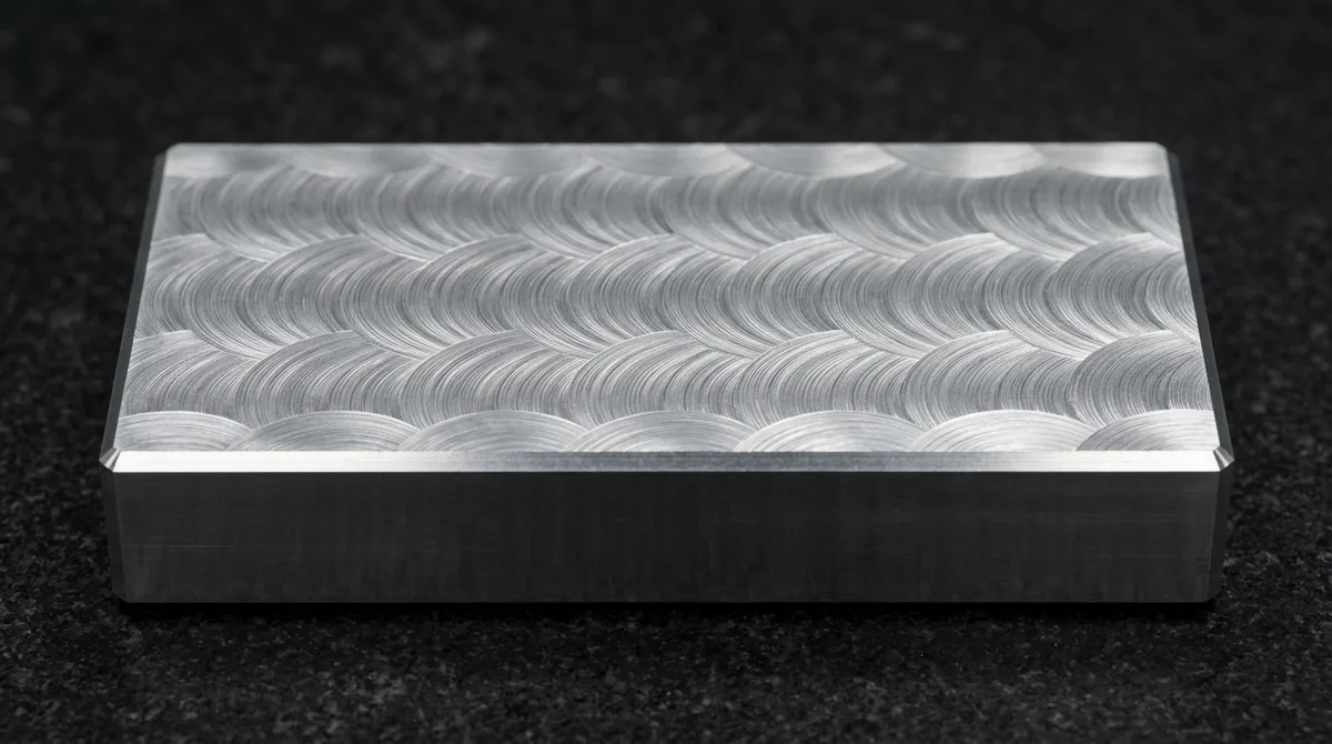
In our machine shop practice, when milling structural aluminum housings, raking directional light reveals the periodic tool marks and feed ridges that define surface lay. Evaluating the micro-topography along and across these feed ridges confirms whether the surface finish satisfies drawing callouts or requires secondary fine lapping.
2. Deciphering Surface Roughness Metrics: Ra vs. Rz vs. 3D Areal Parameters
Arithmetic roughness average (Ra) is the most widely specified surface metric, yet relying solely on Ra without analyzing peak-to-valley height (Rz) or material bearing ratio represents a dangerous engineering pitfall. Two surfaces with radically different micro-topographies can yield identical Ra values while behaving in completely opposite manners during dynamic friction and sealing service.
When selecting surface roughness callouts on 2D engineering drawings, mechanical designers must evaluate the mathematical definitions and physical limitations of each parameter:
1. Ra (Roughness Average / Center Line Average – CLA)
Ra is the arithmetic mean of the absolute values of the profile height deviations (Z) from the mean evaluation line within a standard sampling cutoff length (λc):
Ra = (1 / L) ∫0L |Z(x)| dx
The Ra Limitation: Because Ra averages all profile peaks and valleys, it is completely blind to profile shape. A surface with sharp, abrasive peaks that shred elastomeric hydraulic seals can exhibit the exact same Ra (e.g., 0.8 µm / 32 µin) as a plateau-honed surface with broad bearing plateaus and deep oil-retaining valleys. Ra provides zero information regarding peak sharpness, valley retention depth, or functional contact area.
2. Rz (Average Maximum Peak-to-Valley Height per ISO / DIN)
Under ISO 4287, Rz is calculated as the arithmetic average of the individual maximum peak-to-valley heights across five consecutive sampling cutoff lengths. Rz is extremely sensitive to extreme abrasive peaks and deep localized gouges. For dynamic O-ring seals, pressurized fluid mating faces, and fatigue-critical aerospace spars, Rz is far more informative than Ra in predicting seal leakage and notch-induced fatigue crack initiation. In high-speed milling of 6061-T6, shop-floor measurements consistently show Rz ≈ 4 × Ra to 7 × Ra.
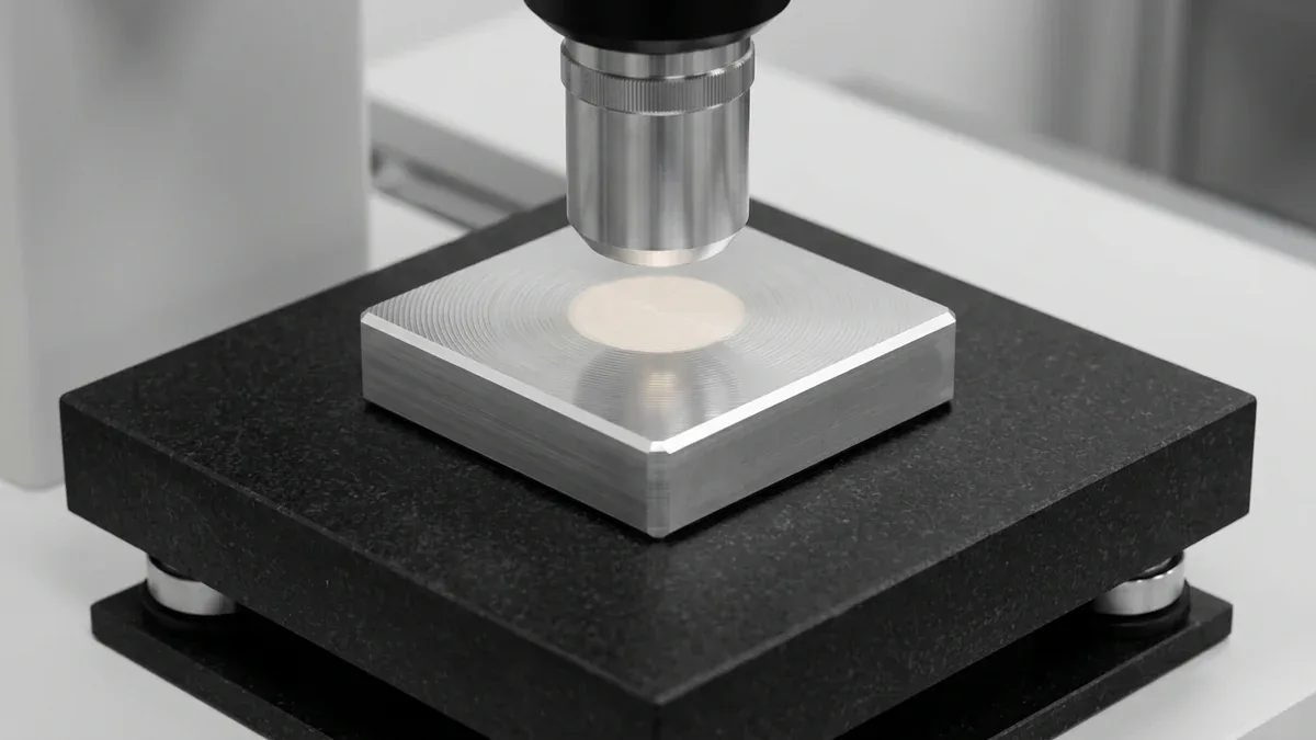
In our metrology laboratory, calibrated contact stylus profilometers (ISO 4287) paired with high-magnification 2.5D optical vision inspection verify surface parameters across precision-machined geometries, mapping peak-to-valley heights and toolpath lay consistency against master reference plaques.
3. Modern 3D Areal Surface Metrology (ISO 25178)
While traditional 2D stylus profilometers trace a single linear path, modern non-contact optical interferometers and confocal microscopes capture true 3D surface topographies across an area:
- Sa (Areal Average Height): The 3D equivalent of Ra, providing comprehensive roughness mapping across freeform surfaces.
- Sz (Maximum Area Height): Sum of the maximum peak height (Sp) and maximum valley depth (Sv) over the measured areal domain.
- Sdr (Developed Interfacial Area Ratio): Measures the percentage increase in actual surface area compared to an ideal flat plane—a critical metric for predicting thermal interface grease contact resistance and anodize oxide adhesion.
- Rsk (Skewness) & Rku (Kurtosis): Rsk quantifies profile asymmetry (negative skewness indicates plateau-like bearing surfaces; positive indicates sharp abrasive peaks). Rku quantifies sharpness of height distribution (Rku > 3 indicates spiky peaks; Rku < 3 indicates flat plateaus).
3. Shop-Floor Kinematic Calculation: Theoretical Roughness vs. Wiper Inserts
In CNC milling and turning, theoretical surface roughness is fundamentally governed by cutting tool geometry and feed rate kinematics. For an end mill or face mill with corner radius Rε operating at feed per tooth fz, the theoretical peak-to-valley cusp height (Rth) generated along the toolpath is calculated using classical cutting mechanics:
Rth ≈ fz² / (8 · Rε)
Consider a standard face-milling operation on an aerospace 6061-T6 aluminum mounting plate using a D50 mm cutter equipped with standard carbide inserts with corner radius Rε = 0.8 mm (0.0315″) running at a finishing feed per tooth fz = 0.12 mm/tooth (0.0047″/tooth):
Rth ≈ (0.12)² / (8 · 0.8) = 0.0144 / 6.4 = 0.00225 mm = 2.25 µm (peak-to-valley height).
Converting kinematic peak height to arithmetic average roughness yields: Ra ≈ Rth / 4 ≈ 0.56 µm (22 µin).
In actual shop-floor cutting, runout, tool wear, and micro-vibration typically increase measured Ra by 20% to 35%, yielding an as-machined finish of Ra ≈ 0.70 to 0.85 µm (28 to 34 µin).
To break through this kinematic limit without reducing feed rate and inflating machining cycle times, our engineers deploy dedicated wiper inserts (wiper flats). A wiper insert features a broad planar secondary cutting edge (length 1.5 to 2.5 mm) positioned parallel to the feed plane.
As the cutter traverses, the wiper flat burnishes away the residual kinematic cusps left by preceding teeth, effortlessly driving surface roughness down to Ra 0.25 to 0.40 µm (10 to 16 µin) while maintaining productive feed rates.
4. Mechanical & Chemical Industrial Texturing Technologies
Achieving specific visual, tactile, or tribological surface textures requires dedicated mechanical blasting, spark erosion, or chemical photo-etching technologies. Each method alters surface micro-topography through distinct physical mechanisms, producing specialized roughness profiles suitable for consumer electronics, automotive interiors, or precision mold tooling.
Understanding these texturing disciplines ensures accurate engineering specifications on component manufacturing drawings:
1. Abrasive Blasting (Bead Blasting & Micro-Etching)
- Spherical Glass Beads (#80 to #220): Propelled at 40 to 80 PSI inside automated blast cabinets, fine spherical glass beads peen the metal surface without sharp cutting action. This cold-peening creates a uniform, non-directional matte satin texture, effectively masking subtle CNC cutter stepover scallops while inducing beneficial compressive residual stresses that elevate fatigue strength. Standard on anodized consumer hardware, handheld instrumentation, and optical bezels.
- Angular Aluminum Oxide (Al₂O₃ Grit): Creates an aggressive, microscopic jagged surface profile (Ra > 3.2 µm / 125 µin) that acts as a mechanical anchor key for powder coating, thermal spray, or structural adhesive bonding.
- Wet Vapor Slurry Blasting: Water-cushioned abrasive slurry delivers ultra-smooth satin finishes (Ra < 0.6 µm / 24 µin) with zero dust embedding and zero edge rounding on precision-machined mating faces.
2. VDI 3400 Electrical Discharge Machining (EDM) Textures
Formulated by the Society of German Engineers (Verein Deutscher Ingenieure), the VDI 3400 scale (VDI 12 to VDI 45) is the global benchmark for spark-eroded textures in hardened tool steel and aluminum injection molds:
- Kinematic Mechanics: Pulsed electrical discharges between the shaped copper or graphite electrode and the steel mold cavity melt and vaporize microscopic craters. The crater diameter and depth correspond directly to discharge pulse energy and on-time.
- Visual Effect: Imparts an isotropic, uniform stippled matte finish to molded plastic parts, concealing cosmetic gate blush, weld knit lines, and minor wall sink marks. For complex internal corners and deep ribs, review our guide to internal sharp corner DFM and EDM texturing.
3. Mold-Tech Chemical Photo-Etching
The Mold-Tech (MT) catalog represents the automotive and consumer hardware standard for complex organic textures. A chemical-resistant photographic mask is applied to the mold surface, followed by multi-stage controlled acid etching:
- MT-11000 Series (Micro-Textures): Fine sand-grain textures (depth 10 to 30 µm / 0.0004 to 0.0012″) for anti-glare instrument bezels.
- MT-9000 & Geometric Series: Diamond patterns, technical stippling, and brushed textures.
- Leather & Organic Grains (MT-10553 / MT-10655): Replicates natural leather pores and animal hides for automotive interior door panels and luxury steering wheel bezels.
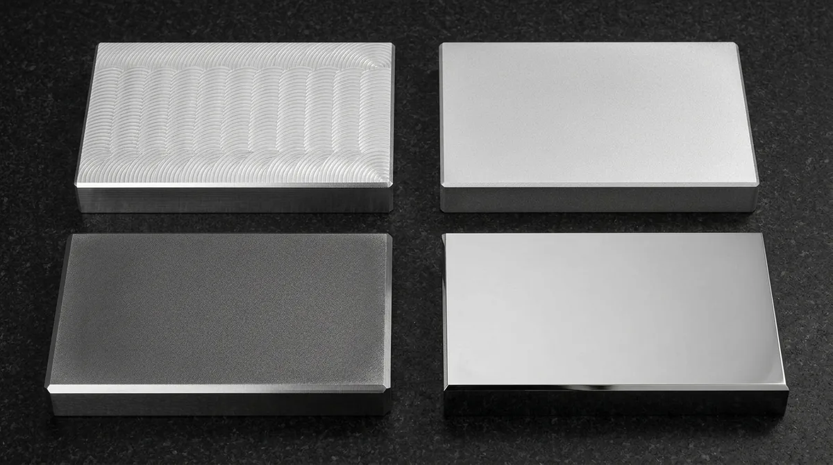
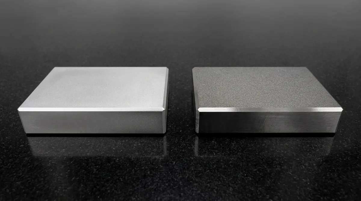
A direct comparison between bead-blasted satin aluminum and VDI 3400 spark-eroded tool steel highlights their distinct micro-topographies. While spherical bead blasting creates smooth, overlapping spherical micro-craters, spark erosion generates sharper, deeper discharge craters with a higher material bearing ratio.
5. Draft Angle Engineering for Textured Mold Tooling
Textured mold cavities require substantial draft angle compensation because surface micro-peaks and valleys act as microscopic mechanical undercuts. When molten polymer solidifies against a textured steel wall, thermal shrinkage locks the plastic tightly into the texture valleys; failing to provide adequate draft causes severe part dragging, gouging, and permanent scuff marks during ejection.
To prevent demolding failures, tooling designers must apply the universal empirical draft compensation equation:
Minimum Draft Angle = Base Part Draft (1.0°) + 1.0° to 1.5° per 0.025 mm (0.001 in) of Texture Depth
For example, applying a Mold-Tech MT-11020 texture (depth ≈ 0.040 mm / 0.0016″) requires a minimum of 3.0° to 3.5° of positive draft per sidewall. For deep leather grains (depth > 0.10 mm / 0.004″), draft angles must exceed 5.0° to 7.0° to ensure clean part release without white stress-blush marks or ejector pin punch-through.
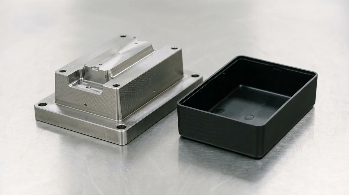
In our tooling room, CNC-machined P20 tool steel mold cores feature chemical-etched sidewall textures paired with positive 3-degree draft angles. Verifying the core geometry alongside first-article molded thermoplastic prototype covers guarantees seamless part ejection with zero drag blemishes.
6. Comprehensive Engineering Matrix: Texture Specifications & Applications
Selecting the optimal surface texture requires balancing functional requirements—such as dynamic sealing, friction coefficients, and paint adhesion—against manufacturing cycle times and tooling costs. The following engineering matrix compares primary industrial surface textures, standardized parameters, and recommended application domains:
| Texture Classification | Standard Spec Reference | Typical Ra Range (µm) | Typical Rz Range (µm) | Additional Draft Required | Tactile / Visual Feel | Recommended Application / When to Choose |
|---|---|---|---|---|---|---|
| Optical Mirror Polish | SPI A-1 / A-2 (Diamond Buff) | 0.012 – 0.050 µm (0.5 – 2 µin) | 0.08 – 0.25 µm | 0.5° (Standard) | Specular high-gloss mirror | Best for optical lenses, light guides, medical implants, and laser mirrors |
| Precision As-Machined CNC | ASME B46.1 (Fine End Milling) | 0.80 – 1.60 µm (32 – 63 µin) | 3.5 – 8.0 µm | 0.0° (Machined vertical) | Smooth with visible circular tool scallops | Best for precision mating faces, mounting flanges, and general structural housings |
| Glass Bead Blasted Satin | MIL-PRF-9954 (Glass Bead #120) | 1.20 – 2.40 µm (48 – 95 µin) | 6.0 – 14.0 µm | N/A (Post-machining) | Uniform non-directional matte sheen | Best for anodized aerospace bezels, consumer electronics, and handheld housings |
| Fine Spark EDM Texture | VDI 3400 Class 18 – 24 | 0.80 – 1.60 µm (32 – 63 µin) | 4.0 – 9.0 µm | +1.0° to +1.5° | Subtle velvety matte stipple | Best for electronic enclosures, automotive interior switches, and anti-fingerprint trims |
| Medium Spark EDM Texture | VDI 3400 Class 27 – 33 | 2.20 – 4.50 µm (88 – 180 µin) | 12.0 – 24.0 µm | +2.0° to +3.0° | Distinct textured matte grip | Best for power tool handles, industrial chassis, and concealing sink/knit lines |
| Fine Chemical Etch Texture | Mold-Tech MT-11010 / MT-11020 | 2.50 – 5.00 µm (100 – 200 µin) | 15.0 – 30.0 µm | +2.5° to +3.5° | Refined sandy stipple grain | Best for automotive center consoles, laptop bottom covers, and medical monitors |
| Deep Coarse Leather Grain | Mold-Tech MT-10553 (Heavy Grain) | 10.0 – 25.0 µm (400 – 1000 µin) | 50.0 – 120.0 µm | +5.0° to +7.0° | Tactile automotive leather pore texture | Best for automotive door trims, luxury instrument panels, and heavy equipment cabs |
7. Engineering Drawing Callout Standards & Metrology Verification
Standardized surface texture callouts per ASME Y14.36M and ISO 1302 prevent ambiguous interpretations between design engineering teams and precision manufacturing suppliers. An incomplete callout that specifies only a numerical value without stating the parameter (Ra vs. Rz), cutoff wavelength, or evaluation length invites costly inspection disputes.
To eliminate ambiguity, 2D production drawings should incorporate complete surface texture symbols containing all three mandatory elements:
- ASME Y14.36M / ISO 1302 Symbol Syntax: A complete surface texture callout utilizes the standardized checkmark symbol with a horizontal top bar. The callout defines parameter type (e.g., Ra 0.8), upper cutoff wavelength (λc = 0.8 mm), manufacturing process requirement (e.g., Milled or Ground), and lay orientation symbol (e.g., ∥ or ⊥).
- Contact Stylus Metrology (ISO 3274): High-precision skidless diamond styli (tip radius r = 2 µm, 60°/90° cone angle) trace across the surface at constant traverse speed (0.5 mm/s). The raw profile is digitally filtered using standard Gaussian cutoff filters to separate short-wavelength roughness from long-wavelength waviness.
- Traceable Master Reference Standards: Daily calibration of shop-floor surface roughness profilometers must be verified against precision-lapped, diamond-turned nickel reference specimens traceable to national metrological institutes (NIST / PTB).
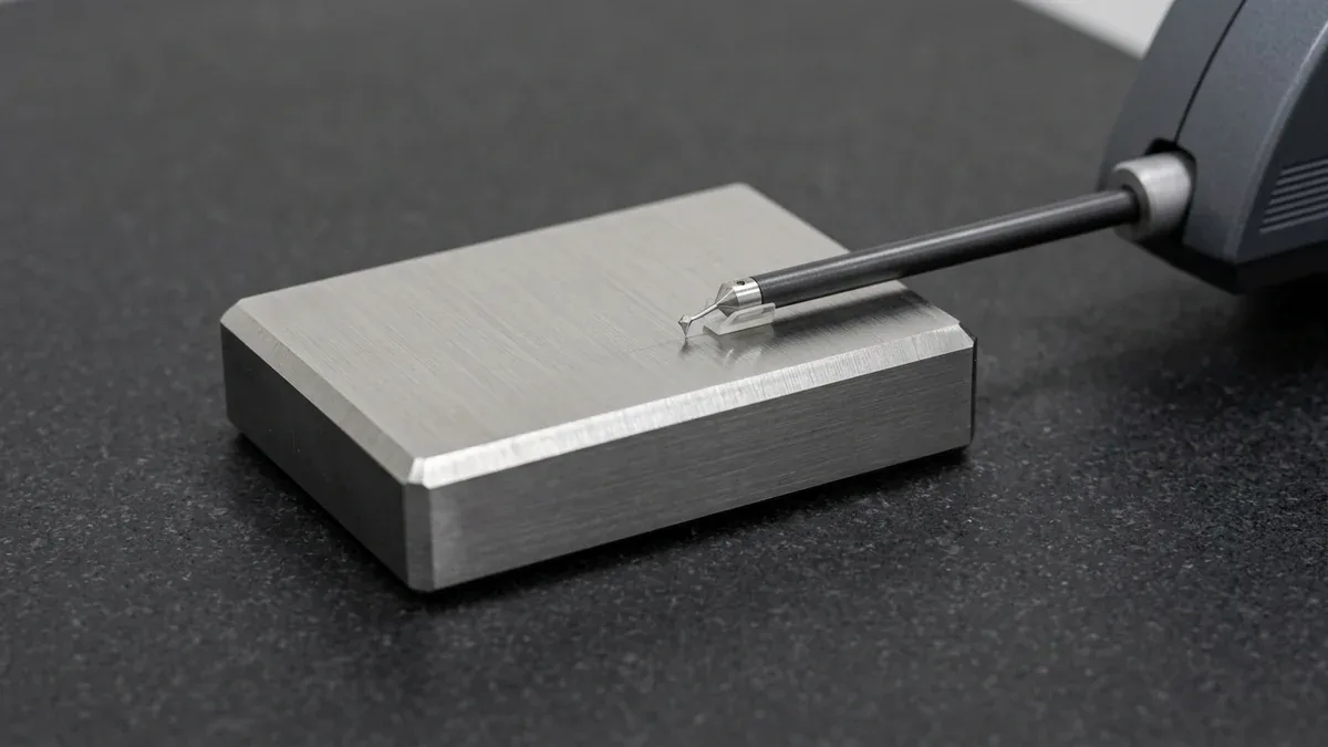
During shop-floor quality verification, our inspectors use a tactile diamond stylus profilometer to measure precision roughness reference standards resting on a black granite plate. Verifying gauge calibration daily against known Ra specimens ensures that every prototype batch complies strictly with drawing tolerances.
8. Shop-Floor Surface Texture Troubleshooting: Root Causes & Corrective Actions
Diagnosing surface roughness anomalies requires tracing the root cause across tooling dynamics, machine kinematics, and workpiece metallurgy. When machined or molded surfaces fail quality inspection, our manufacturing engineers deploy a structured troubleshooting sequence to eliminate defects immediately:
1. Defect: Periodic Waviness and Chatter Marks in Face Milling
Symptom: Regular ripple pattern visible across milled surface; Ra fluctuates wildly between 1.2 µm and 4.8 µm across the cutter path.
Root Cause: Tool overhang ratio exceeds 3:1 (inducing bending deflection), spindle harmonic resonance matches tooth-pass frequency, or dynamic clamping flexure.
Corrective Action: Switch from equidistant tooth pitch to variable-pitch cutter body; reduce tool overhang to minimum gage length; switch to climb milling; install hydraulic toolholder with high vibration dampening.
2. Defect: Micro-Tearing and Built-Up Edge (BUE) on 6061-T6 Aluminum
Symptom: Matte, cloudy streaks with microscopic torn flakes along the cutting path; stylus traces reveal sharp positive spikes (positive Rsk).
Root Cause: Cutting velocity (Vc) is too low (entering the thermal welding zone below 150 m/min); inadequate lubricity allows aluminum to weld to the carbide rake face.
Corrective Action: Elevate cutting speed to Vc = 350 to 500 m/min; equip cutter with polished uncoated carbide inserts or DLC (Diamond-Like Carbon) coatings; apply high-pressure 8% to 10% water-soluble emulsion or pure MQL ester oil.
3. Defect: Demolding Scuff Marks on Textured Mold Cavities
Symptom: Longitudinal white stress marks and scraped plastic shavings along textured vertical sidewalls upon mold opening.
Root Cause: Insufficient draft angle relative to texture depth; high cavity packing pressure forcing polymer deeply into micro-undercuts; inadequate mold cooling.
Corrective Action: Increase draft angle by at least 1.5° per 0.025 mm of texture depth; reduce second-stage packing pressure; apply nickel-PTFE release coating to mold sidewalls; delay ejection until part temperature drops below glass transition (Tg).
9. Technical Engineering FAQ
Ra is an arithmetic average that fails to differentiate between sharp abrasive peaks and deep lubricating valleys. For hydraulic or O-ring seals, Rz (mean peak-to-valley height), Rsk (skewness), and Rmr (material bearing ratio) must be controlled to prevent seal abrasion or fluid leakage.
Each 0.025 mm (0.001 in) of texture depth demands an additional 1.0° to 1.5° of positive draft beyond base geometry. Heavier textures like VDI 3400 #30 or Mold-Tech MT-11020 require 3.0° to 5.0° of draft per sidewall to prevent severe drag marks during ejection.
VDI 3400 textures are produced electro-chemically during EDM die sinking, generating isotropic, non-directional stippled matte surfaces. Chemical etching (Mold-Tech) applies acid-resistant photographic masking to etch organic geometric grains, leather patterns, or fine micro-textures into tool steel.
Standard CNC milling typically achieves Ra 1.6 to 3.2 µm (63 to 125 µin). By utilizing specialized wiper inserts, high-speed spindles (15,000+ RPM), and light stepovers, finishing passes achieve Ra 0.4 to 0.8 µm (16 to 32 µin) directly off the machine.
Specify Verified Surface Finishes on Custom Precision Components
Ensure dimensional allowance control, thread masking accuracy, and MIL-A-8625 or ASTM surface compliance from raw billet machining through final finishing. Upload your 3D CAD models and 2D prints for a complete engineering DFM review.
Upload CAD & Drawings for Finishing DFM Review